

RANE MP2015
I
CUE
CUE
CUE
CUE
CUE
II
III
IV
IIIIII
IV
SUBMIX
MIX
MIX
MIX
MIX
MIX
FILTER
LOW
MID
HIGH
FILTER
FILTER
FILTER
FILTER
LEVEL
PAN
TONE
GAIN
SESSION OUT
SESSION IN
BOOTH
MAIN
LEFT
RIGHT
MIC
AUX
SPLIT
DUCK
SUB
SUB
ACTIVE
SUB
SUB
SUB
FX ON
SUB
MAIN
OFF
PHONES
LOW
MID
HIGH
LOW
MID
HIGH
LOW
MID
HIGH
GAIN
SOURCE
LOW
CROSSOVER
CROSSOVER
MID
SOURCE
SOURCE
SOURCE
GAIN
GAIN
GAIN
LOW
MID
HIGH
RESONANCE
FX LOOP
HIGH
ISO
MI XER MANUAL
0 dB
225
135 380
+10
∞
80
640
PH/CD 1 AUX
1A
3
2
1
0
OFF|+6 OFF|+6 OFF|+6 OFF|+6
OFF|+6 OFF|+6 OFF|+6 OFF|+6
OFF|+6 OFF|+6 OFF|+6 OFF|+6
456
7
9
10 0
1B
8
OL
+10
+7
+5
+3
+2
+1
0
-1
-2
-3
-5
-7
-10
-15
-24
PH/CD 2 AUX
2A
456
3
2
1
0 dB
+10
∞
OL
+10
+7
+5
+3
+2
+1
0
-1
-2
-3
-5
-7
-10
-15
-24
PH/CD 3 AUX
3
2
1
2B
7
8
9
10 0
1.7k 4.75k
1.0k
3A
456
10 0
2.8k
∞
8.0k
OL
+10
+7
+5
+3
+2
+1
0
-1
-2
-3
-5
-7
-10
-15
-24
PH/CD 4 AUX
4A
456
3
2
1
3B
7
8
9
0 dB
OL
+10
+7
+5
+3
+10
4B
7
8
9
10
OL
+10
+7
+5
+3
+2
+1
0
-1
-2
-3
-5
-7
-10
-15
-24
+2
+1
-10
-15
-24
DRY WET
OFF|+6
OFF|+6
OFF|+6
0
-1
-2
-3
-5
-7
OL
+10
+7
+5
+3
+2
+1
-1
-2
-3
-5
-7
-10
-15
-24
3
2
1
3
2
1
0
5
4
6
0
10
456
7
9
0
10
456
3
2
1
0
10
456
3
2
1
0
10
456
3
2
1
0
10
BASS TREBLE
7
8
9
8
7
8
9
7
8
9
7
8
9
LOW HIGH
CUE MIX
456
3
5
4
3
2
1
6
7
8
9
10
5
4
3
2
1
6
7
8
9
100
5
4
3
2
1
6
7
8
9
100
5
4
3
2
1
6
7
8
9
100
3
2
1
456
0
7
8
9
100
2
1
7
8
9
0
10
MP2015 MANUAL
Important Safety Instructions
1. Read these instructions.
2. Keep these instructions.
3. Heed all warnings.
4. Follow all instructions.
5. Do not use this apparatus near water.
6. Clean only with a dry cloth.
7. Do not block any ventilation openings. Install in accordance with manufacturer’s instructions.
8. Do not install near any heat sources such as radiators, registers, stoves, or other apparatus (including ampliers) that produce heat.
9. Do not defeat the safety purpose of the polarized or grounding-type plug. A polarized plug has two blades with one wider than the other. A
grounding-type plug has two blades and a third grounding prong. The wide blade or third prong is provided for your safety. If the provided
plug does not t into your outlet, consult an electrician for replacement of the obsolete outlet.
10. Protect the power cord and plug from being walked on or pinched particularly at plugs, convenience receptacles, and the point where it exits
from the apparatus.
11. Only use attachments and accessories specied by Rane.
12. Use only with the cart, stand, tripod, bracket, or table specied by the manufacturer, or sold with the apparatus. When a cart is used, use
caution when moving the cart/apparatus combination to avoid injury from tip-over.
13. Unplug this apparatus during lightning storms or when unused for long periods of time.
14. Refer all servicing to qualied service personnel. Servicing is required when the apparatus has been damaged in any way, such as power
supply cord or plug is damaged, liquid has been spilled or objects have fallen into the apparatus, the apparatus has been exposed to rain or
moisture, does not operate normally, or has been dropped.
15. The plug on the power cord is the AC mains disconnect device and must remain readily operable. To completely disconnect this apparatus
from the AC mains, disconnect the power supply cord plug from the AC receptacle.
16. This apparatus shall be connected to a mains socket outlet with a protective earthing connection.
17. When permanently connected, an all-pole mains switch with a contact separation of at least 3 mm in each pole shall be incorporated in the
electrical installation of the building.
18. If rackmounting, provide adequate ventilation. Equipment may be located above or below this apparatus, but some equipment (like large
power ampliers) may cause an unacceptable amount of hum or may generate too much heat and degrade the performance of this apparatus.
19. This apparatus may be installed in an industry standard equipment rack. Use screws through all mounting holes to provide the best suppor t.
WARNING: To reduce the risk of re or electric shock, do not expose this apparatus to rain or moisture. Apparatus shall not be exposed to
dripping or splashing and no objects lled with liquids, such as vases, shall be placed on the apparatus.
WARNING
CAUTION
RISK OF ELECTRIC SHOCK
DO NOT OPEN
ATTENTION: RISQUE DE CHOCS ELECTRIQUE - NE PAS OUVRIR
To reduce the risk of electrical shock, do not open the unit. No
user serviceable parts inside. Refer servicing to qualied service
personnel.
WARNING: This product may contain chemicals known to the State of California to cause cancer, or birth defects or other reproductive harm.
NOTE: This equipment has been tested and found to comply with the limits for a Class B digital device, pursuant to part 15 of the FCC
Rules. These limits are designed to provide reasonable protection against harmful interference in a residential installation. This equipment
generates, uses and can radiate radio frequency energy and, if not installed and used in accordance with the instructions, may cause harmful
interference to radio communications. However, there is no guarantee that interference will not occur in a particular installation. If this
equipment does cause harmful interference to radio or television reception, which can be determined by turning the equipment off and on,
the user is encouraged to try to correct the interference by one or more of the following measures:
• Reorient or relocate the receiving antenna.
• Increase the separation between the equipment and receiver.
• Connect the equipment into an outlet on a circuit dif ferent from that to which the receiver is connected.
• Consult the dealer or an experienced radio/ TV technician for help.
CAUTION: Changes or modications not expressly approved by Rane Corporation could void the user's authority to operate the equipment.
This Class B digital apparatus complies with Canadian ICES-003.
The symbols shown below are internationally accepted symbols
that warn of potential hazards with electrical products.
This symbol indicates that a dangerous voltage
constituting a risk of electric shock is present
within this unit.
This symbol indicates that there are important
operating and maintenance instructions in the
literature accompanying this unit.
MP2015 MANUAL
2
Instructions de Sécurité
1. Lisez ces instructions.
2. Gardez précieusement ces instructions.
3. Respectez les aver tissements.
4. Suivez toutes les instructions.
5. Ne pas utiliser près d’une source d’eau.
6. Ne nettoyer qu’avec un chiffon doux.
7. N’obstruer aucune évacuation d’air. Effectuez l’installation en suivant les instructions du fabricant.
8. Ne pas disposer près d’une source de chaleur, c-à-d tout appareil produisant de la chaleur sans exception.
9. Ne pas modier le cordon d’alimentation. Un cordon polarisé possède 2 lames, l’une plus large que l’autre. Un cordon avec tresse de masse
possède 2 lames plus une 3è pour la terre. La lame large ou la tresse de masse assurent votre sécurité. Si le cordon fourni ne correspond pas à
votre prise, contactez votre électricien.
10. Faites en sorte que le cordon ne soit pas piétiné, ni au niveau du l, ni au niveau de ses broches, ni au niveau des connecteurs de vos appareils.
11. N’utilisez que des accessoires recommandés par Rane.
12. N’utilisez que les éléments de transport, stands, pieds ou tables spéciés par le fabricant ou vendu avec l’appareil. Quand vous utlisez une
valise de transpor t, prenez soin de vous déplacer avec cet équipement avec prudence an d’éviter tout risque de blessure.
13. Débranchez cet appareil pendant un orage ou si vous ne l’utilisez pas pendant un certain temps.
14. Adressez-vous à du personnel qualié pour tout service après vente. Celui-ci est nécessaire dans n’importe quel cas où l’appareil est abimé :
si le cordon ou les ches sont endommagés, si du liquide a été renversé ou si des objets sont tombés sur l’appareil, si celui-ci a été exposé à la
pluie ou l’humidité, s’il ne fonctionne pas correctement ou est tombé.
15. La che du cordon d’alimentation sert à brancher le courant alternatif AC et doit absolument rester accessible. Pour déconnecter totalement
l’appareil du secteur, débranchez le câble d’alimentation de la prise secteur.
16. Cet appareil doit être branché à une prise terre avec protection.
17. Quand il est branché de manière permanente, un disjoncteur tripolaire normalisé doit être incorporé dans l’installation électrique de l’immeuble.
18. En cas de montage en rack, laissez un espace sufsant pour la ventilation. Vous pouvez disposer d’autres appareils au-dessus ou en-dessous
de celui-ci, mais certains (tels que de gros amplicateurs) peuvent provoquer un buzz ou générer trop de chaleur au risque d’endommager votre
appareil et dégrader ses performances.
19. Cet appareil peut-être installé dans une baie standard ou un chassis normalisé pour un montage en rack. Visser chaque trou de chaque oreille
de rack pour une meilleure xation et sécurité.
ATTENTION: an d’éviter tout risque de feu ou de choc électrique, gardez cet appareil éloigné de toute source d’humidité et
d’éclaboussures quelles qu’elles soient. L’appareil doit également être éloigné de tout objet possédant du liquide (boisson en
bouteilles, vases,…).
ATTENTION
CAUTION
RISK OF ELECTRIC SHOCK
Les symboles ci-dessous sont reconnus internationalement comme
prévenant tout risque électrique.
Ce symbole indique que cette unité utilise un voltage
élevé constituant un risque de choc électrique.
DO NOT OPEN
ATTENTION: RISQUE DE CHOCS ELECTRIQUE - NE PAS OUVRIR
An d’éviter tout risque de choc électrique, ne pas ouvrir l’appareil.
Aucune pièce ne peut être changée par l’utilisateur. Contactez un
SAV qualié pour toute intervention.
REMARQUE: Cet équipement a été testé et approuvé conforme aux limites pour un appareil numérique de classe B, conformément au chapitre
15 des règles de la FCC. Ces limites sont établis pour fournir une protection raisonnable contre tout risque d’interférences et peuvent provoquer
une énergie de radiofréquence s'il n'est pas installé et utilisé conformément aux instructions, peut également provoquer des interférences aux
niveaux des équipements de communication. Cependant, il n'existe aucune garantie que de telles interférences ne se produiront pas dans
une installation particulière. Si cet équipement provoque des interférences en réception radio ou télévision, ceci peut être detecté en mettant
l'équipement sous/hors tension, l'utilisateur est encouragé à essayer de corriger cette inter férence par une ou plusieurs des mesures suivantes:
• Réorienter ou déplacer l'antenne de réception.
• Augmenter la distance entre l'équipement et le récepteur.
• Connecter l'équipement à une sortie sur un circuit différent de celui sur lequel le récepteur est branché.
• Consulter un revendeur ou un technicien radio / TV expérimenté.
ATTENTION: Les changements ou modications non expressément approuvés par Rane Corporation peuvent annuler l'autorité de l'utilisateur à
manipuler cet équipement et rendre ainsi nulles toutes les conditions de garantie.
Cet appareil numérique de classe B est conforme à la norme Canadienne ICES-003.
Cet appareil numérique de classe B est conforme à la norme Canadienne NMB-003.
Ce symbole indique la présence d’instructions
d’utilisation et de maintenance importantes dans le
document fourni.
MP2015 MANUAL
3

Copyright Notices
©2015 Rane Corporation. All rights reserved. Windows® is a registered trademark of Microsoft Corporation in the United
States and other countries. Apple, Mac, Macintosh, iTunes, Safari, QuickTime, GarageBand, and OS X are registered
trademarks of Apple Inc., registered in the United States and other countries. ASIO is a trademark of Steinberg Media
Technologies GMBH. Traktor, Traktor Pro and Maschine are trademarks of Native Instruments GMBH. Virtual DJ is a
registered trademark of Atomix Productions Inc. Ableton is a trademark of Ableton AG.
Check List
These items are included in the box:
• MP2015 Mixer.
• 1 USB cable.
• 1 control panel install disc.
• IEC C5 line cord.
• This MP2015 Mixer Manual.
Wear Parts
The MP2015 Mixer contains no wear parts. See "Limited Warranties" on page 25.
MP2015 MANUAL
4

Contents
2 Important Safety Instructions
4 Copyright Notices
4 Check List
6 MP2015 Overview
8 Connections
9 Deck Input Channels
10 Session Input and Output
10 Submix
13 Headphone Cueing
13 Microphone Input
13 Main Mix Outputs
14 USB Audio
15 DJ Changeover
16 Class Compliant USB Ports
16 Control Panel
18 MIDI Mapping
20 MIDI Implementation
23 Technical Specifications
24 Declaration of Conformity
25 Limited Warranties
MP2015 MANUAL
5

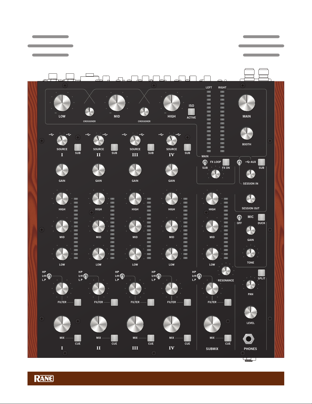
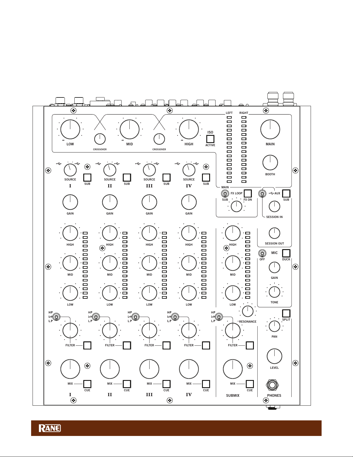
MP2015 Overview
Highest quality user control surface
• Excellent control ergonomics with intuitive and comfortable layout.
• Potentiometers with exceptional feel and 1 million cycle life.
• Studio console grade backlit push switches.
Digital Signal Processing
• A/D and D/A dynamic range 116 dB A-weighted, THD+N 0.0009%.
• All audio processing is 32-bit oating point with supported sample rates: 44.1 kHz, 48 kHz or 96 kHz.
• S/PDIF inputs for each Deck and Session input with
• Dynamic range 128 dB with ultra-low jitter and 16:1 SRC conversion range.
• S/PDIF Session output to record mix or chain mixers together without analog conversion.
2 USB por ts allow simultaneous connection of 2 computers
• Each USB port supports 10 playback and 14 record channels.
• Simultaneously record 4 Decks, Submix, Session In and Main mix.
• USB 2.0 high-speed class compliant MIDI and Audio
• Driver installation is not required for Mac OSX.
• High-performance universal ASIO driver is provided for Windows.
• User control panel supports user options and status.
Analog I/O designed with attention to detail
• Accurate, low noise RIAA stages with 3rd-order Infrasonic (rumble) and 2nd order low-pass lters.
• Transient voltage and EMI protection, turn on muting and overload protection.
• 8 Vrms balanced outputs, 4 Vrms unbalanced I/O.
Four Deck inputs with these features:
• Select USB A, PH/CD, AUX or USB B input with Gain trim and RIAA Phono sensitivity.
• Deck 1 USB playback channels 1-2
• Deck 2 USB playback channels 3-4
• Deck 3 USB playback channels 5-6
• Deck 4 USB playback channels 7-8
• 3-band full-cut EQ with 2 selectable crossover points: Linkwitz-Riley 2nd-order
• 4th-Order Selectable Low-pass, Low/High-pass, or High-pass lter with Mode, Resonance and on/off controls.
• Main Mix Level control, Headphone Cue, Submix assign, 16-segment Q-peak meter with Peak-hold.
Session Input with Level control
• Source may be unbalanced RCA, S/PDIF or USB AUX playback channels 9-10.
• Assigned to Main Mix or Submix, where the submix can act as a fth input channel.
Microphone input with 48 volt phantom power and Line-level switches
• Combo XLR and 1/4" TRS input jack.
• May be used with a condenser mic, dynamic mic or line-level (wireless) input.
• Input Level control, 1-knob Tone control, on/off switch and Duck controls.
Unique Submix feature
• Group any number of inputs for easy and intuitive multi-source mixing.
• Channels assigned to the Submix share a common set of controls, similar to the Deck inputs.
• Assignable external Effects Loop with sensitivity, in/out and wet/dry control.
High performance Integrated Isolator EQ
• 4th-order Linkwitz-Riley 3-band Isolator with adjustable crossover points. Exceptionally smooth.
Main Mix with 16-segment stereo Meter
• Balanced XLR Main Output with Level control.
• Balanced 1/4" TRS Booth Output with Level control.
• Session Output with Level control.
• S/PDIF output for digital recording or chaining mixers together.
• Unbalanced RCA analog output.
• Effects Loop may be assigned to the Main Mix or just the Submix.
Headphone monitor
• Level Control, Cue/Main Pan, Mono Split or Stereo Cue.
• Conveniently located 3.5 mm and 1/4" jacks on the top plate and front panel.
MP2015 MANUAL
6
USB Record outputs:
I
CUE
CUE
CUE
CUE
CUE
II
III
IV
IIIIII
IV
SUBMIX
MIX
MIX
MIX
MIX
MIX
FILTER
LOW
MID
HIGH
FILTER
FILTER
FILTER
FILTER
LEVEL
PAN
TONE
GAIN
SESSION OUT
SESSION IN
BOOTH
MAIN
LEFT
RIGHT
MIC
AUX
SPLIT
DUCK
SUB
SUB
ACTIVE
SUB
SUB
SUB
FX ON
SUB
MAIN
OFF
PHONES
LOW
MID
HIGH
LOW
MID
HIGH
LOW
MID
HIGH
GAIN
SOURCE
LOW
CROSSOVER
CROSSOVER
MID
SOURCE
SOURCE
SOURCE
GAIN
GAIN
GAIN
LOW
MID
HIGH
RESONANCE
FX LOOP
HIGH
ISO
• USB record channels 1-2: Deck 1 post-fader by default, pre-fader option in the control panel.
• USB record channels 3-4: Deck 2 post-fader by default, pre-fader option in the control panel.
• USB record channels 5-6: Deck 3 post-fader by default, pre-fader option in the control panel.
• USB record channels 7-8: Deck 4 post-fader by default, pre-fader option in the control panel.
• USB record channels 9-10: Main Mix.
• USB record channels 11-12: Submix.
• USB record channels 13-14: Session Output.
0 dB
225
135 380
+10
∞
80
640
PH/CD 1 AUX
1A
3
2
1
OFF|+6 OFF|+6 OFF|+6 OFF|+6
OFF|+6 OFF|+6 OFF|+6 OFF|+6
OFF|+6 OFF|+6 OFF|+6 OFF|+6
456
0
10 0
1B
7
8
9
OL
+10
+7
+5
+3
+2
+1
0
-1
-2
-3
-5
-7
-10
-15
-24
PH/CD 2 AUX
2A
456
3
2
1
0 dB
+10
∞
OL
+10
+7
+5
+3
+2
+1
0
-1
-2
-3
-5
-7
-10
-15
-24
PH/CD 3 AUX
3
2
1
2B
7
8
9
10 0
1.7k 4.75k
1.0k
3A
456
10 0
2.8k
∞
8.0k
OL
+10
+7
+5
+3
+2
+1
0
-1
-2
-3
-5
-7
-10
-15
-24
PH/CD 4 AUX
4A
456
3
2
1
3B
7
8
9
0 dB
OL
+10
+7
+5
+3
+10
4B
7
8
9
10
OL
+10
+7
+5
+3
+2
+1
0
-1
-2
-3
-5
-7
-10
-15
-24
+2
+1
-10
-15
-24
DRY WET
OFF|+6
OFF|+6
OFF|+6
0
-1
-2
-3
-5
-7
OL
+10
+7
+5
+3
+2
+1
0
-1
-2
-3
-5
-7
-10
-15
-24
456
3
2
1
0
456
3
2
1
0
3
2
1
3
2
1
3
2
1
BASS TREBLE
10
456
0
456
0
456
0
7
8
9
10
7
8
9
7
8
9
10
7
8
9
10
7
8
9
10
LOW HIGH
CUE MIX
456
3
5
4
3
2
1
6
7
8
9
10
3
2
1
456
7
8
9
100
3
2
1
456
7
8
9
100
3
2
1
456
7
8
9
100
3
2
1
456
0
7
8
9
100
2
1
MP2015 MANUAL
7
8
9
0
10
7
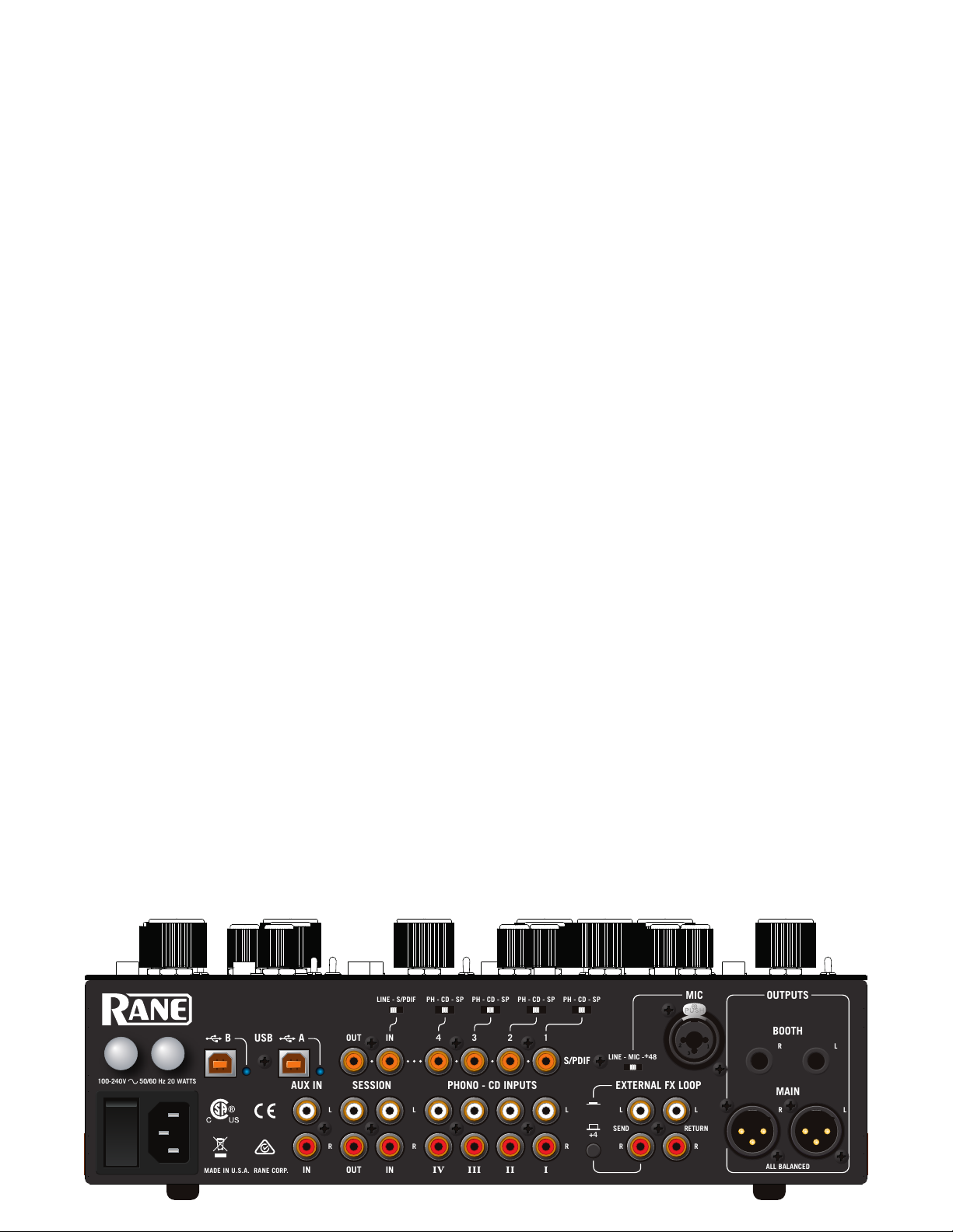
Connections
100-240V 50/60 Hz 20 WATTS
MADE IN U.S.A. RANE CORP.
ABUSB
SESSION
PHONO - CD INPUTS
BOOTH
MIC
OUTPUTS
MAIN
IN4321
OUT
IN
IN
IV
IIIIII
OUT
EXTERNAL FX LOOP
AUX IN
LINE - S/PDIF
PH - CD - SP
PH - CD - SP
PH - CD - SP
PH - CD - SP
LINE - MIC -+48
SEND
LLL
R
LRR
L
S/PDIF
RLRLR
R
RETURN
ALL BALANCED
+4
Mixer Inputs
• One stereo Phono / CD input is provided for each of the four channels on a red and white pair of RCA jacks. If your CD
players have S/PDIF outputs, connect these to the orange S/PDIF inputs. Each channel may be set for PH, CD or SP
using rear panel slide switches. Set unused inputs to CD. Connect your turntable ground wires to the ground posts
provided on the rear panel when using PH inputs.
• Computer control panel: Phono Sensitivity adjustment to match source levels. See "Control Panel" on page 16.
• There is one stereo unbalanced AUX IN on RCA jacks. This input may be selected by any of the four Deck channels.
• One stereo Session Input is available as analog on a pair of red and white RCA jacks, or digitally using the orange S/PDIF
jack. Select the input type with the LINE / S/PDIF switch. Use this input to connect two mixers together. Using S/PDIF
Session Input with another mixer's S/PDIF Session Output can digitally link mixers without converting to analog.
• This input may also be a general purpose auxiliary input to the mixer, assigned to the Main mix or Submix. If it's
assigned to the Submix, it can be a 5th input with it's own tone and lter controls like the rst 4 channels.
• The balanced microphone input on a combination TRS / XLR jack can be switched to:
• LINE level for the output of a wireless mic receiver.
• MIC level for a regular dynamic microphone.
• +48 V Phantom power for a condenser microphone.
• Stereo FX Loop Return input is on a pair of unbalanced RCA jacks. The FX Return input is normally used in combination
with the FlexFX Send output to connect an outboard effects processor.
Mixer Outputs
All of these outputs carry the same Main mix signal, each with its own Level control:
• MAIN Output is on a pair of balanced XLR jacks.
• BOOTH Output is on a pair of balanced 1/4" TRS jacks.
• SESSION Out is on a pair of unbalanced RCA jacks, and digitally via S/PDIF on an RCA jack.
The FX Loop Send output is available on a pair of unbalanced RCA jacks. The FlexFX Send output is normally used in
combination with the FlexFX Loop Return input to connect outboard analog effects. The Main mix is sent to effects.
• The SEND output level can be switched to -10 (for unbalanced devices) or +4 (for balanced devices).
Cabling Note: When using unbalanced 1/4" tip-sleeve cables from the Booth Outputs, or RCA cables from the analog
Session Outputs, keep cables short, less than 3 meters (10 feet) to avoid hum and interference. Balanced 1/4" TRS or XLR
cables are the best choice, allowing greater distance runs without problems.
Two USB Ports
The MP2015 allows simultaneous connection of two computers, each port completely independent. The USB ports are
100% class compliant, allowing hook-up to Mac OSX without the need for an additional driver. A high-performance ASIO
driver connects the audio in most Windows DAW and DJ software. MIDI end points are class compliant with both OSX and
Windows devices. Connect either port to a single computer. See "Class Compliant USB Ports" on page 16.
Power Supply
The MP2015 Mixer features an internal universal switching power supply that operates on any AC mains 100 to 240 VAC, 50
or 60 Hz (most places in the world). All that is required when traveling is the appropriate IEC line cord, available from a local
electronics store. The universal supply is a major plus for the traveling DJ. Though this mixer has turn on/off muting, it’s
smart to leave the power unplugged until everything else is connected.
MP2 015
MP2015 MANUAL
-10
8
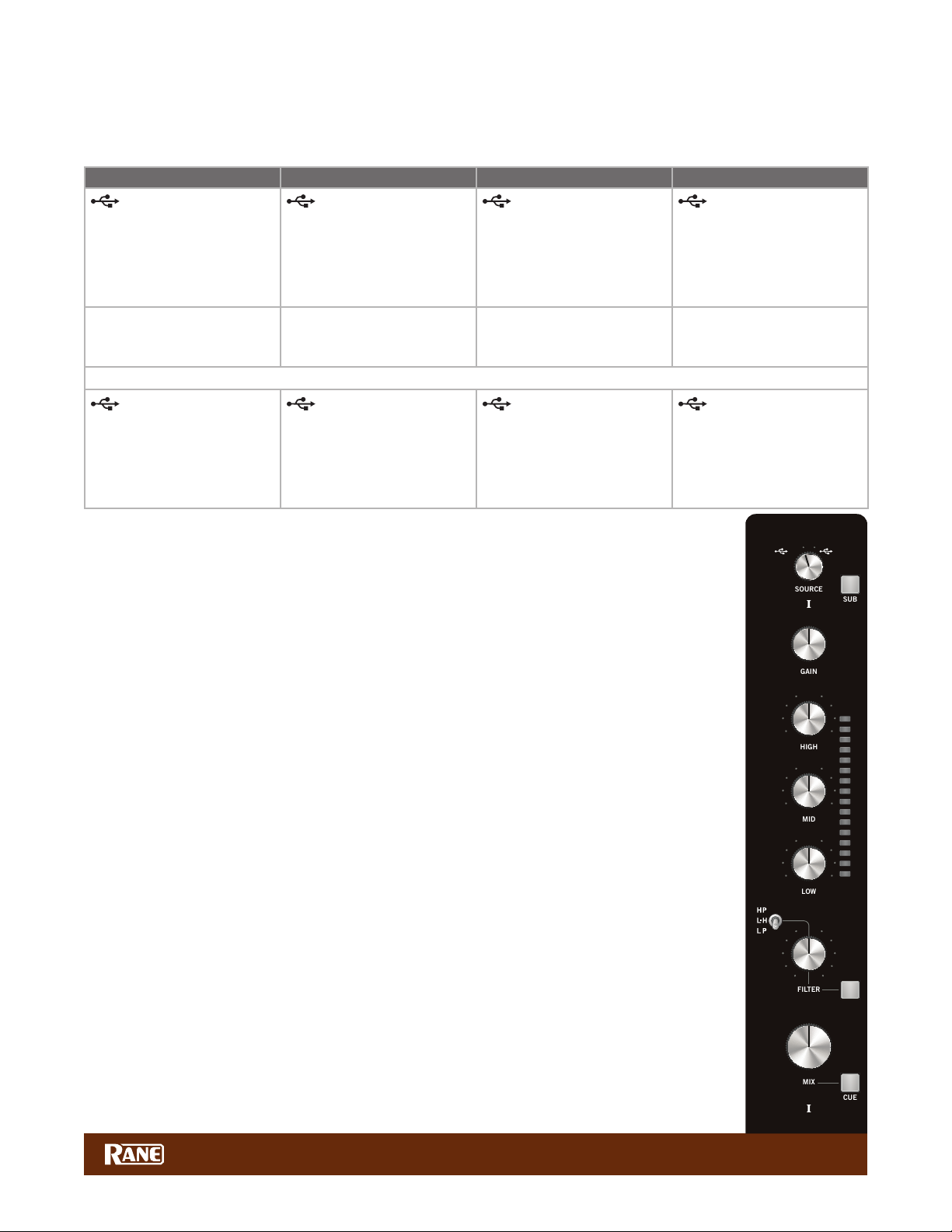
Deck Input Channels
I
CUE
I
MIX
FILTER
LOW
MID
HIGH
SUB
GAIN
SOURCE
Source Selectors
The source selectors choose the active USB port, USB audio slot or analog input for each input channel. To use USB
playback you must assign the USB slots in your DJ or DAW software preferences panel.
Deck 1 Source Selections Deck 2 Source Selections Deck 3 Source Selections Deck 4 Source Selections
Port A playback for
Deck 1
• USB audio slots 1-2.
• Routes audio and MIDI for
Deck 1 only to/from USB
Port A.
• Phono / CD 1
• Set the PH-CD-SP switch
on the rear panel.
Port B playback for
Deck 1
• USB audio slots 1-2.
• Routes audio and MIDI for
Deck 1 only to/from USB
Port B.
Port A playback for
Deck 2
• USB audio slots 3-4.
• Routes audio and MIDI for
Deck 2 only to/from USB
Port A.
• Phono / CD 2
• Set the PH-CD-SP switch
on the rear panel.
• Aux Input (common to all selectors).
Port B playback for
Deck 2
• USB audio slots 3-4.
• Routes audio and MIDI for
Deck 2 only to/from USB
Port B.
Port A playback for
Deck 3
• USB audio slots 5-6.
• Routes audio and MIDI for
Deck 3 only to/from USB
Port A.
• Phono / CD 3
• Set the PH-CD-SP switch
on the rear panel.
Port B playback for
Deck 3
• USB audio slots 5-6.
• Routes audio and MIDI for
Deck 3 only to/from USB
Port B.
Port A playback for
Deck 4
• USB audio slots 7-8.
• Routes audio and MIDI for
Deck 4 only to/from USB
Port A.
• Phono / CD 4
• Set the PH-CD-SP switch
on the rear panel.
Port B playback for
Deck 4
• USB audio slots 7-8.
• Routes audio and MIDI for
Deck 4 only to/from USB
Port B.
For details on sharing the MP2015 with a second computer, see "DJ Changeover" on page 15.
Deck Source Selection is followed by:
• GAIN trim
• Off to +15 dB with unity gain at 12 o’clock.
• 3-band HIGH / MID / LOW tone controls
• Off to +6 dB with unity gain at 12 o’clock.
• Linkwitz-Riley 2nd-order isolator full-cut lters (LR-2).
• Crossover points for Low/Mid and Mid/High default at 300 Hz between Low and Mid, 3 kHz
between Mid and High. This can be changed for each Deck. See "Control Panel" on page 16.
• High-Pass / Low-High-Pass / Low-Pass Sweep FILTER
• Low-pass lter cutoff moves from 20 kHz toward 20Hz as the knob is turned CCW.
• High-pass lter cutoff moves from 20 Hz toward 20kHz as the knob is turned CW.
• In Low-High mode, there is no effect at the center (at response).
• Low-pass increases CCW from the center.
• High-pass increases CW from the center.
• Resonance can be adjusted for all Sweep Filters with the RESONANCE control.
• CUE select
• Assigns a Deck to the headphone monitor.
• Q-peak meter with peak hold
• Adjust the GAIN trim to get the signal into the yellow during peaks, and to prevent overload.
• MIX control
• Adjusts the channel level feeding the USB record outputs, Submix or Main mix.
• Submix
• When the SUB button (next to the Source selector) is pressed and lit blue, the Deck is sent to the
Submix. When this button is off, the channel is sent to the Main Mix. See "Submix" on page 10.
See "Main Mix Outputs" on page 13.
PH/CD 1 AUX
1A
456
3
2
1
0
OFF|+6
OFF|+6
OFF|+6
456
3
2
1
0
1B
7
8
9
10
OL
+10
+7
+5
+3
+2
+1
0
-1
-2
-3
-5
-7
-10
-15
-24
7
8
9
10
MP2015 MANUAL
9

Session Input and Output
SESSION OUT
SESSION IN
AUX
SUB
Session input sources may be unbalanced RCA, digital S/PDIF, or USB audio channels 9/10. Session
input can be used independently to provide an additional stereo input to the mixer, or in conjunction
with Session Out to chain mixers together.
Connect any line-level device (e.g., a CD player, another DJ mixer, an iPod, iPhone, etc.) to the
Session In RCA white and red jacks. The orange S/PDIF input connects a digital device (e.g., a CDJ
2000 or another MP2015 mixer) using a single RCA cable. Use the switch above the jacks to select
the S/PDIF input or the RCA inputs as a source. Alternatively, USB Aux audio channels 9/10 can be
selected as the Session input source using the toggle switch next to the Session In level control.
Session Output is available on unbalanced analog white and red RCA jacks and an orange digital S/PDIF jack. These
outputs can be used for auxiliary zone output, in combination with Session Input when chaining mixers together or for
external digital S/PDIF main mix recording. Both of these outputs are active at the same time.
Note: Using S/PDIF provides better sound and higher performance when connecting an available S/PIDF source like an
equipped CDJ or another mixer.
To play audio coming from a device plugged into the RCA or S/PDIF Session Inputs, set the USB AUX toggle switch
to SESSION IN (down position). To play audio from USB audio channels 9/10 set the USB AUX switch to USB AUX (up
position). To use USB AUX playback, you must assign USB channels 9/10 in your DJ or DAW software preferences panel.
Assigning the Session Input to the Submix (press the SUB button) essentially turns this 4-channel mixer into a fullfeatured 5-channel mixer with the Submix channel providing independent 3-band EQ, Filter, Mix Level and Cue.
You can simultaneously record the Session Input, channels 1, 2, 3, 4, Submix, and the Main output through USB audio
channels. Multitrack recording allows you to “x” a recording in the studio. See "USB Audio" on page 14.
The Session Out control affects the level of audio output on the Session Out RCA jacks, S/PDIF jack and USB Record
channels 13-14.
2
2
3
1
3
1
456
0
456
0
7
8
9
10
7
8
9
10
Real World Session I/O Application
If you are a Traktor and Maschine user, you may typically use a combination of four track decks and/or remix decks within
Traktor as well as hits, loops, and samples coming from Maschine.
Route your four tracks/remix decks to the four channels on the MP2015 and then route the main output of Maschine
through the Session Input via USB AUX channels 9/10. Set the audio routing in the Traktor Preferences.
Use the Session In gain to control the audio volume coming from Maschine. You can send the audio from Maschine to
the Submix by pressing the Session In SUB button, giving you full Mix level, EQ, and Filtering. Alternatively, you can take
advantage of Maschine’s discrete audio through the Deck channels to the Submix for ease of multi-source mixing and/or to
add an external effect.
Submix
The Submix is a channel that you can send any or all audio to, just as you do with the main mix. The Submix may include
any combination of the four Deck Inputs and the Session Input. Press the SUB button on any Deck or the Session In to
assign it to the Submix, lighting the button blue. This allows grouping any number of inputs for easy and intuitive multisource mixing. The concept is identical to a Submix or bus track on a typical audio mixing console. This capability is
important for grouping a number of tracks together onto one channel for ease of control and processing.
• Channels assigned to the Sub Mix share a common set of controls:
• Main MIX Level.
• 3-band full-cut tone controls. Crossover points for Low/Mid and Mid/High can be changed. See "Control Panel" on
page 16.
• 16-segment Q-peak meter with peak hold.
• Headphone CUE.
• Selectable High-Pass / Low-High-Pass / Low-Pass Sweep FILTER.
• Note: The Resonance control affects all Sweep Filters for Decks 1, 2, 3, 4 and the Submix.
• Assignable external Effects Loop:
• The FX Send level can be switched on the rear panel to -10 (for low-voltage devices) or +4 (for higher-voltage devices).
• FX ON button activates the effects loop when lit, receiving input from the FX RETURN jacks.
• Wet / Dry controls the ratio of FX to the mix.
• This Loop may be switched to process the Main Mix or the Submix.
• USB Record output for the Submix is on channels 11-12.
MP2015 MANUAL
10

Why add a Submix to a DJ mixer?
CUE
SUBMIX
MIX
FILTER
LEFT
RIGHT
FX ON
SUB
MAIN
LOW
MID
HIGH
RESONANCE
FX LOOP
One huge leap forward in DJ technology is the introduction of auto sync. Using CDJs, Traktor,
Virtual DJ, Ableton, or most any DJ software, the sync feature opens the gates to creative multisource mixing. New technology offers new possibilities, and might make you rethink how you mix.
A Submix removes the burden of having to simultaneously manage separate gain, EQ, and lter
controls for multiple channels when mixing multiple sources. Grouping the tracks together within
the Submix allows one simple set of controls to easily control Mix level, EQ and Filter settings for
multiple channels, turning one control instead of 2, 3 or 4 all at once.
When mixing two sources, you probably won’t use the Submix, unless you want to add an
external effect to one or both of the channels. The Submix is key for DJs needing to easily and
intuitively mix multiple sources at once.
Using the Submix
Let's look at an example with three sources of audio coming from software:
• The main track is on channel 1, a drum loop on channel 2, and a looped sample on channel 3.
• There is a breakdown coming up in the main track and you want to lter out the Low/Mid range
while turning down the gain of the tracks on channels 2 and 3 going into the breakdown.
• Before assigning channels to the Submix, make certain that doing so initially has a neutral affect
on what is being played. Turn the Submix Mix control all the way up, set the tone controls at 12
o’clock, and turn off the Filter within the Submix channel. This ensures that the audio sent to the
Submix is initially unaffected by the Submix routing.
• Press the SUB buttons next to the Source selector on both channels 2 and 3. This sends the
audio of both channels to the Submix.
• Now you can control both tracks on channels 2 and 3 using the Submix control strip.
• As you get closer to the breakdown about to happen on the channel 1 track:
• Turn on the Filter within the Submix channel.
• Start ltering out the Low and Mid range frequencies with the Filter control.
• Turn down the level of both tracks with the MIX knob in the Submix.
Mix successfully executed!
Without a Submix, you would need to turn on two Filters, adjust two Filter controls and turn down
two Mix controls to execute the same mix. Adding more tracks to the mix makes this process even
harder to manage and could land in a sea of uncontrolled sound and a confused dance oor.
OL
+10
+7
+5
+3
+2
+1
-10
-15
-24
DRY WET
OFF|+6
OFF|+6
OFF|+6
0
-1
-2
-3
-5
-7
LOW HIGH
OL
+10
+7
+5
+3
+2
+1
0
-1
-2
-3
-5
-7
-10
-15
-24
Submix and the External FX Loop
The Submix features an external effects insert, allowing you to add effects to assigned channels.
The external FX controls are located at the top of the Submix channel strip:
1. FX ON button: sends and returns audio from an outboard effects processor.
3
2
1
456
0
7
8
9
10
2. MAIN / SUB switch: allows you to choose whether you want to add an effect to audio coming into
the Submix or to the Main mix.
3. WET / DRY: controls the amount of the effect.
You'll nd the RCA Send and Return jacks and a level switch on the rear panel. Here's how it works:
1. Connect the MP2015 SEND to the input of your external effects processor.
2. Connect the output of the effects processor to the MP2015 RETURN.
a. If you use a consumer-grade effects processor, such as the Korg Kaoss Pad, engage the -10 switch by pressing it in.
This matches the I/O level of the external effects processor to the MP2015.
3. Select SUB or MAIN mix as the location for the effects insert:
• If you want the effect on everything, select MAIN.
• If you want the effect only on the Submix selected intputs, select SUB.
a. For the Main mix, set the effects assign toggle to MAIN then simply press the FX ON button to engage the FX Loop
and rotate the control toward WET until you hear the desired effect amount.
b. To apply an effect to channels assigned to the Submix, set the FX Loop assign to SUB. Send the desired channels to
the Submix. Turn the FX ON and adjust WET / DRY as desired.
c. To avoid any change in your mix when sending channels to the Submix, make sure the MIX knob in the Submix is
turned all the way up, the tone controls are dead center at 12 o’clock, and the FILTER switch is turned off.
MP2015 MANUAL
11

Submix Signal Flow
I
CUE
CUE
CUE
CUE
CUE
II
III
IV
IIIIII
IV
SUB MIX
MIX
MIX
MIX
MIX
MIX
FILTER
LOW
MID
HIGH
FILTER
FILTER
FILTER
FILTER
BOOTH
MAIN
LEFT
RIGHT
SUB
(ON)
ACTIVE
SUB
(ON)
SUB
(off)
SUB
(off)
LOW
MID
HIGH
LOW
MID
HIGH
LOW
MID
HIGH
GAIN
SOURCE
LOW
CROSSOVER
CROSSOVER
MID
SOURCE
SOURCE
SOURCE
GAIN
GAIN
GAIN
LOW
MID
HIGH
FX LOOP
HIGH
ISO
SESSION IN
SESSION IN
AUX
SESSION OUT
SUB
(ON)
(off)
ISO
SUB
through
FX LOOP
MAIN
through
FX LOOP
FX ON
FX (off)
Starting from the Source selectors, the signal passes through the Gain, Tone, Filter and Mix controls. This graphic has the
SUB buttons, Session In and FX control positions re-arranged to more easily see the signal ow.
• If SUB is not pressed (see Decks 1 and 2) then the signal goes to the FX Loop (if it's on), then the ISO EQ (if it's on),
then to the Main Outputs.
• If SUB is pressed (see Decks 3, 4, and Session In) then the signals are combined and go through another set of
Tone, Filter and Mix controls. From here, the Submix can go through the FX Loop (if it's on), then the ISO EQ (if it's
on), then to the Main Outputs.
0 dB
225
∞
PH/CD 1 AUX
1A
456
3
2
1
0
OFF|+6 OFF|+6 OFF|+6 OFF|+6
OFF|+6 OFF|+6 OFF|+6 OFF|+6
135 380
+10
80
PH/CD 2 AUX
1B
7
8
9
10 0
2
640
2A
3
1
456
0 dB
∞
+10
PH/CD 3 AUX
2B
7
8
9
10 0
3
2
1
1.7k 4.75k
1.0k
3A
456
10 0
2.8k
∞
8.0k
PH/CD 4 AUX
3B
7
8
9
2
4A
3
1
456
0 dB
OL
+10
+7
+5
+3
+10
4B
7
8
9
10
2
1
3
456
0
7
8
9
10
+2
+1
0
-1
-2
-3
-5
-7
-10
-15
-24
3
2
1
3
2
1
2
456
0
456
0
456
3
1
0
OFF|+6
OFF|+6
7
8
9
10
7
8
9
10
7
8
9
10
OFF|+6 OFF|+6 OFF|+6 OFF|+6
3
2
1
456
456
3
7
2
8
1
9
10
7
8
9
100
3
2
1
456
3
7
2
8
1
9
100
456
7
8
9
100
MP2015 MANUAL
3
2
1
OFF|+6
456
0
LOW
7
8
9
100
DRY WET
12

Microphone Input
LEVEL
PAN
TONE
GAIN
MIC
SPLIT
DUCK
OFF
PHONES
SESSION OUT
SESSION IN
BOOTH
MAIN
LEFT
RIGHT
AUX
SUB
ACTIVE
FX ON
SUB
MAIN
LOW
CROSSOVER
CROSSOVER
MID
FX LOOP
HIGH
ISO
135 380
OL
+10
+7
+5
+3
+2
+1
0
-1
-2
-3
-5
-7
-10
-15
-24
0
2
1
3
456
7
8
9
10
∞
0 dB
+10
∞
0 dB
+10
∞
0 dB
+10
0
2
1
3
456
7
8
9
10
DRY WET
0
2
1
3
456
7
8
9
10
0
2
1
3
456
7
8
9
10
80
225
640
1.7k 4.75k
1.0k
2.8k
8.0k
The mic input has these controls:
• On / Off switch turns the mic on or off.
• Duck momentarily ducks other inputs by 10 dB (by about 1/3).
• Gain control sets the mic level.
• One-knob spectral tilt Tone control:
• Increasing highs reduces lows by the same amount.
• Decreasing highs increases lows by the same amount.
• A rear panel switch has 3 positions for different mic types:
• Line level accepts the output from a wireless mic receiver.
• Mic level is suitable for a dynamic mic.
• 48V phantom power is for a condenser mic.
• Control panel option: with Clean Feed selected, the Mic signal is sent directly to the Main Out and is
not present in the USB Main Record, Booth Out or Session Out. See "Control Panel" on page 16.
Headphone Cueing
• The Headphone monitor provides stereo or mono split cue operation.
• When set for stereo operation (off), the Pan control pans between stereo Cue and stereo Main Mix.
• When set for Split Cue operation (ON), the Pan control pans between Mono Cue in the left ear and
mono Main Mix in the right ear.
• Individual Cue buttons are provided for Deck 1, Deck 2, Deck 3, Deck 4, and Submix.
• Cue buttons are solo, meaning when a Cue is selected all other Cues are turned off. If you wish to
listen to more than one Cue at a time, press both buttons at the same time.
• The Phones control sets the level to the headphone jacks.
• Headphones output is available on two 1/4" jacks, one on the front and one on the top. An additional
3.5mm jack is located on the front. All share the same signal.
• The Control Panel allows Bass and Treble adjustment in headphones. See "Control Panel" on page 16.
• Note: the Main Output Isolator is not heard in the headphones.
456
3
2
1
0
10
BASS TREBLE
CUE MIX
456
3
2
1
0
10
7
8
9
7
8
9
Main Mix Outputs
• These signals combine
to make the Main Mix
signal:
• Decks 1, 2, 3, and 4.
• Session In.
• Submix / FX Return.
• Mic.
• Main Mix outputs are:
• Main: balanced XLR jacks with a maximum output of 8 volts rms.
• Booth: balanced 1/4" TRS jacks with a maximum output of 8 volts rms.
• Session: unbalanced RCA jacks with a maximum output of 4 volts rms.
• S/PDIF digital session output on one RCA jack.
• Common to all Main Mix outputs:
• Stereo Q-peak meter with peak hold:
• If the red overload LED is off, the mixer will not clip at any output level setting.
• Main Output Isolator:
• Off to +10 dB with unity gain at 12 o’clock.
• Low-mid crossover is adjustable from 80 Hz to 640 Hz.
• Mid-high crossover is adjustable from 1 kHz to 8 kHz.
• Main, Booth and Session outputs have independent Level controls; range is off to 0
dB.
• Control panel option: the Main Output can be set to Mono or Stereo. Other outputs remain in stereo. See "Control Panel"
on page 16.
MP2015 MANUAL
13

USB Audio
I
CUE
CUE
CUE
CUE
CUE
II
III
IV
IIIIII
IV
SUBMIX
MIX
MIX
MIX
MIX
MIX
FILTER
LOW
MID
HIGH
FILTER
FILTER
FILTER
FILTER
LEVEL
PAN
TONE
GAIN
SESSION OUT
SESSION IN
BOOTH
MAIN
LEFT
RIGHT
MIC
AUX
SPLIT
DUCK
SUB
SUB
ACTIVE
SUB
SUB
SUB
FX ON
SUB
MAIN
OFF
PHONES
LOW
MID
HIGH
LOW
MID
HIGH
LOW
MID
HIGH
GAIN
SOURCE
LOW
CROSSOVER
CROSSOVER
MID
SOURCE
SOURCE
SOURCE
GAIN
GAIN
GAIN
LOW
MID
HIGH
RESONANCE
FX LOOP
HIGH
ISO
There are seven stereo record channels and ve stereo playback channels. These channels are available on two USB ports,
allowing two computers to share the device. This allows two DJs to play together, and supports uninterrupted transitions
between them. USB audio is 24-bit PCM with a sample rate of 44.1, 48 or 96 kHz. Sample rate and USB slot assignments
are made in the preferences screen in your DJ or digital audio workstation software.
Deck 1 PlaybackUSB 1-2
USB RECORD
USB 3-4
USB 5-6
USB 7-8
USB 9-10
Deck 1 Record
Deck 2 Record
Deck 3 Record
Deck 4 Record
Main Mix Record
Deck 2 Playback
Deck 3 Playback
Deck 4 Playback
Session In Playback
USB 1-2
USB 3-4
USB 5-6
USB 7-8
USB 9-10
USB PLAYBACK
+10
PH/CD 3 AUX
2
3
2
1
3A
3
1
1.7k 4.75k
456
456
2.8k
1.0k
8.0k
3B
7
8
9
10 0
7
8
9
100
0 dB
∞
PH/CD 4 AUX
4A
456
3
2
1
OL
+10
+7
+5
+3
+2
+1
0
-1
-2
-3
-5
-7
-10
-15
-24
456
3
2
1
135 380
+10
1B
7
8
9
10 0
OL
+10
+7
+5
+3
+2
+1
0
-1
-2
-3
-5
-7
-10
-15
-24
7
8
9
10
0 dB
225
∞
80
640
PH/CD 2 AUX
2B
2A
456
3
7
2
8
9
1
10 0
OL
+10
+7
+5
+3
+2
+1
0
-1
-2
-3
-5
-7
-10
-15
-24
456
3
7
2
8
1
9
100
0 dB
∞
PH/CD 1 AUX
1A
456
3
2
1
0
OFF|+6 OFF|+6 OFF|+6 OFF|+6
OFF|+6 OFF|+6 OFF|+6 OFF|+6
OFF|+6 OFF|+6 OFF|+6 OFF|+6
456
3
2
1
x2 USB Ports
OL
456
+10
3
7
+7
2
8
+5
+3
1
9
+2
0
OFF|+6
OFF|+6
OFF|+6
0
456
DRY WET
+1
-10
-15
-24
0
-1
-2
-3
-5
-7
LOW HIGH
100
10
456
3
7
2
8
9
1
0
10
456
3
7
2
8
1
9
0
10
456
3
7
8
2
OL
9
1
+10
10
0
+7
+5
+3
+2
+1
456
3
7
0
2
8
-1
1
9
-2
0
10
-3
-5
-7
-10
-15
-24
BASS TREBLE
CUE MIX
456
3
7
2
8
9
1
7
0
10
8
9
+10
4B
7
8
9
10
OL
+10
+7
+5
+3
+2
+1
0
-1
-2
-3
-5
-7
-10
-15
-24
3
7
2
8
1
9
100
Submix Record
USB 11-12
Session In Record USB 13-14
USB Playback Channels Assignment
Deck 1 Playback Deck 2 Playback Deck 3 Playback Deck 4 Playback Session In USB Playback
In USB audio
playback slots 1-2.
In USB audio
playback slots 3-4.
In USB audio
playback slots 5-6.
In USB audio
playback slots 7-8.
In USB audio playback slots
9-10.
Routed from either USB A or USB B depending on the Deck Input source selection. Sum of USB A and USB B.
USB Record Channel Assignment (Broadcast to both USB A and USB B at all times).
Deck 1
Record
In USB audio
record slots
1-2.
Deck 2
Record
In USB audio
record slots
3-4.
Deck 3
Record
In USB audio
record slots
5-6.
Deck 4
Record
In USB audio
record slots
7-8.
Main Mix
Record
In USB audio
record slots
9-10.
Submix
Record
In USB audio
record slots
11-12.
Session In
Record
In USB audio
record slots
13-14.
Select "Phono / CDJ" for DVS. Select "Post" for multi-track
recording (default). See "Control Panel" on page 16.
MP2015 MANUAL
14

DJ Changeover
IIIIII
IV
SUB
SUB
SUB
SUB
SOURCE
SOURCE
SOURCE
SOURCE
I
CUE
CUE
CUE
CUE
CUE
II
III
IV
IIIIII
IV
SUBMIX
MIX
MIX
MIX
MIX
MIX
FILTER
LOW
MID
HIGH
FILTER
FILTER
FILTER
FILTER
LEVEL
PAN
TONE
GAIN
SESSION OUT
SESSION IN
BOOTH
MAIN
LEFT
RIGHT
MIC
AUX
SPLIT
DUCK
SUB
SUB
ACTIVE
SUB
SUB
SUB
FX ON
SUB
MAIN
OFF
PHONES
LOW
MID
HIGH
LOW
MID
HIGH
LOW
MID
HIGH
GAIN
SOURCE
LOW
CROSSOVER
CROSSOVER
MID
SOURCE
SOURCE
SOURCE
GAIN
GAIN
GAIN
LOW
MID
HIGH
RESONANCE
FX LOOP
HIGH
ISO
One of the biggest challenges of digital DJing has been seamlessly changing over from one DJ to the next and playing
back-to-back DJ sets. With the dual USB architecture of the MP2015 mixer, changeover between digital DJs has never
been easier.
PH/CD 1 AUX
Deck Changeover Controls
1A
At the top of each input channel is the Source Selector
to switch input sources. If your computer is connected
to USB port A, switch a channel Source Select knob to
USB A, and the mixer assigns the corresponding virtual deck to that channel for audio playback. For example, assigning all
four channels to USB 1A-4A assigns all four virtual decks to the computer connected to USB port A.
The same applies to USB port B. If your computer is connected to USB port B, switching a channel Source Select knob
to USB B, assigns the corresponding virtual deck to that channel for audio playback.
When two DJs are connected to the MP2015, they can quickly swap deck control between computers using the Source
Select knobs. Any of the four inputs can be swapped back and forth with a simple knob twist. Nice and easy, just the way
we intended.
The DJ Changeover Walkthrough
In the scenario below, one DJ, let’s call him DJ A, is already connected to the MP2015 using either USB port A or B. With
DJ A’s computer already connected and playing music, do the following:
1. Connect your computer to the unused USB port on the MP2015.
2. Switch the Input Source on a non-playing input channel to the USB source of your computer.
PH/CD 2 AUX
1B
2A
PH/CD 3 AUX
2B
3A
PH/CD 4 AUX
3B
4B
4A
3. Play a track on this Deck and mix it in when you're ready — audio from both computers are in the mix.
4. Fade out the audio playing from DJ A’s computer to the audio playing from your computer.
5. Assign the Input Source for the remaining free mixer channel(s) to your computer and continue DJing.
When DJ A is done, disconnect his computer from the USB port. If you’re back-to-back mixing with DJ A, keep the
computer connected and perform the same swapping instructions to regain deck control.
USBUSB
MIC
TURNTABLE OUT
0 dB
0 dB
0 dB
225
135 380
+10
+10
∞
CD OUT CD OUT
∞
80
640
PH/CD 1AUX
PH/CD 2AUX
PH/CD 3AUX
1B1A
2B2A
456
456
3
3
7
3
7
2
2
8
2
8
9
9
1
1
1
10 0
10 0
0
OL
OL
+10
+10
+7
+7
OFF|+6 OFF|+6 OFF|+6 OFF|+6
+5
+5
+3
+3
+2
+2
+1
+1
0
0
-1
-1
-2
-2
OFF|+6 OFF|+6 OFF|+6 OFF|+6
-3
-3
-5
-5
-7
-7
-10
-10
-15
-15
-24
-24
OFF|+6 OFF|+6 OFF|+6 OFF|+6
456
456
3
3
7
3
7
2
2
8
2
8
1
1
9
1
9
100
10
OL
456
+10
3
7
+7
2
8
+5
2.8k
+3
1
1.7k 4.75k
∞
1.0k
8.0k
PH/CD 4AUX
3B3A
456
456
3
7
2
8
9
1
10 0
OL
+10
+7
+5
+3
+2
+1
0
-1
-2
-3
-5
-7
-10
-15
-24
456
456
3
7
2
8
1
9
100
9
+2
+10
0
10
+1
0
-1
456
-2
3
7
-3
2
8
4B4A
-5
9
1
-7
0
10
-10
-15
-24
7
456
3
7
8
8
2
9
9
1
10
10
0
DRY WET
456
3
7
8
2
OL
OL
9
1
+10
+10
10
0
+7
+7
OFF|+6
+5
+5
+3
+3
+2
+2
+1
+1
456
3
7
0
0
2
8
-1
-1
1
9
-2
-2
OFF|+6
0
10
-3
-3
-5
-5
-7
-7
-10
-10
-15
-15
-24
-24
BASS TREBLE
OFF|+6
LOW HIGH
CUE MIX
456
3
7
2
8
456
9
1
3
7
7
0
10
2
8
8
1
9
9
0
100
100
TURNTABLE OUT
MP2015 MANUAL
15

Class Compliant USB Ports
The USB ports are 100% class compliant, connecting to Mac OSX without the need for an additional driver. A highperformance ASIO driver runs most Windows DAW and DJ software. MIDI end points are class compliant with both OSX
and Windows devices. Mac and Windows Control Panel installers with additional mixer settings are included on the CDROM with the MP2015, and current versions available from the Downloads link in the MP2015 page at dj.rane.com.
ASIO (Windows)
A low-latency ASIO driver interfaces with most DJ and DAW audio software applications on Windows operating systems.
Multi-client ASIO allows different audio software applications to simultaneously stream audio to and from the MP2015. If
the same playback channel is selected in more than one application, the driver mixes the audio from the applications before
streaming it to the device. ASIO driver and Rane Control Panel system requires Windows 7-SP1, Windows 8 or 8.1. The
driver Control Panel may be launched from the Windows Control Panel. Select Start > Control Panel > Rane MP2015.
Core Audio (Macintosh)
No driver installation is required. Connect the MP2015 to a Mac running OSX, and the MP2015 inputs and outputs become
available in your audio program. Install the Rane control panel to provide additional setting as described below.
Control Panel
NOTE: Settings are saved in the mixer. The control panel for Windows or Macintosh is updated with the mixer’s settings.
Therefore, when you connect to a different MP2015 Mixer, it's saved settings override your previous Control Panel settings.
NOTE: The Rane Control Panel and Firmware may be updated with new features over time. To get the most from your
MP2015, occasionally check the Downloads link in the MP2015 page at dj.rane.com.
Settings
The MP2015 allows you to save and export settings. You can load your preferences when using a different MP2015 than
your own, or putting things back after another DJ has used your mixer.
Once you have set control panel preferences, click Export to write these to a computer le. Click Import to load a .rms
settings le. The control panel shows the current settings le loaded in the mixer. If any changes are made since the last
import, [Modied] will appear after the lename along with a Save button, offering to save your changes as the new default.
Firmware
The MP2015 Firmware Version currently installed in the MP2015 is shown. The Downloads link on the MP2015 page at
dj.rane.com is the place to check if there is a control panel / rmware update. After downloading and installing, if the
MP2015 rmware installed on your computer is newer than the rmware in your MP2015, an Update Firmware button is
enabled. Pressing the button updates the MP2015 rmware to the new version.
General Tab
Main Out can be set to Stereo or Mono. The Booth and
Session Outputs are always in stereo.
Headphone Tone slider adjusts the tone going to the
headphones using spectral tilt lters.
• Increasing Treble reduces lows by the same amount.
• Increasing Bass reduces highs by the same amount.
Sub Tone Crossover sets the crossover points of the
3-band Tone controls in the Submix to either:
• 300 Hz between Low and Mid, 3 kHz between Mid and
High.
• 150 Hz between Low and Mid, 6 kHz between Mid and High (default).
Mic Clean Feed when selected, the microphone signal is only sent to the Main Out and is not present in the USB Main
Record, Booth Out or Session Out. This allows you to record your set without any house announcements. Default is Off.
MP2015 MANUAL
16

Port MIDI Enable enables MIDI commands to/from the MP2015 Mixer controls at the current USB Port. Default is Off.
Port MIDI Channel assigns MIDI channel 1-16 to the MP2015 Mixer at the current USB Port. Default is MIDI channel 1.
USB Port Status indicates the connection status of both USB ports. Active indicates a USB connection between the mixer
and a computer. Local shows the USB Port connected to this control panel's computer.
The Buffer Size control allows the USB buffer to be increased or decreased. This only appears in the Rane Control Panel
for ASIO in Windows. In Mac systems, the buffer control is in the DAW or DJ audio preferences screen and does not appear
here. The Rane driver is designed to run at latencies as low as 5 milliseconds round-trip. However, computer performance
and available resources (number of applications running) may adversely affect the computer’s ability to stream audio
reliably. If pops and clicks are heard in USB audio, try increasing the buffer size to eliminate them. With ASIO, total roundtrip latency is equal to Buffer Size plus device latency. With Core Audio, total round-trip latency is determined by the Buffer
Size set by the DAW/DJ software, plus device latency. Device latency is 3 to 4 ms.
Deck Inputs I-IV Tab
There is one panel for each input channel on the mixer.
Each Deck panel controls these functions:
Analog Input Source: The analog input for each Deck
must be set appropriately for CD, Phono or S/PDIF using
a switch on the rear of the mixer. The control panel shows
the mode selected by these switches for each of the four
inputs. This mode can only be changed on the mixer.
Phono Sensitivity: If a Phono Input is selected on
the mixer (as shown for Decks I and IV), the Sensitivity
adjustment appears in the panel. Click the down-arrow to
display a list of 16 Sensitivity settings between 2.5mV and
10mV in 0.5mV steps. The default is 5mV. Set the Phono
Sensitivity to the same level of your cartridge (see your cartridge documentation for the correct value). Another method is to
match the level of the turntable to a CD playing on another input.
USB Record Source: These controls select one of two sources for each input channel as the USB record source.
• Phono / CD will record the source pre-Mix control, used for DVS applications.
• Deck (1-4) Post records each deck after the Mix control, used for multitrack recording. Each Deck records to separate
USB slots. This is the default setting. See "USB Audio" on page 14.
Tone Crossover sets the crossover points of the 3-band Tone controls for each of the Deck channels to either:
• 300 Hz between Low and Mid, 3 kHz between Mid and High.
• 150 Hz between Low and Mid, 6 kHz between Mid and High (default).
MP2015 MANUAL
17

MIDI Mapping
I
CUE
CUE
CUE
CUE
CUE
II
III
IV
IIIIII
IV
SUBMIX
MIX
MIX
MIX
MIX
MIX
FILTER
LOW
MID
HIGH
FILTER
FILTER
FILTER
FILTER
LEVEL
PAN
TONE
GAIN
SESSION OUT
SESSION IN
BOOTH
MAIN
LEFT
RIGHT
MIC
AUX
SPLIT
DUCK
SUB
SUB
ACTIVE
SUB
SUB
SUB
FX ON
SUB
MAIN
OFF
PHONES
LOW
MID
HIGH
LOW
MID
HIGH
LOW
MID
HIGH
GAIN
SOURCE
LOW
CROSSOVER
CROSSOVER
MID
SOURCE
SOURCE
SOURCE
GAIN
GAIN
GAIN
LOW
MID
HIGH
RESONANCE
FX LOOP
HIGH
ISO
Top Panel MIDI Controls
0 dB
2 10 24 39
+10
∞
PH/CD 1 AUX
1A
1B
225
135 380
9
80
640
PH/CD 2 AUX
2A
0 dB
2.8k
1.7k 4.75k
+10
∞
2B
PH/CD 3 AUX
17
1.0k
8.0k
3A
3B
57 54 50 45
22 18 15
456
3
2
1
1
0
10 0
7
8
9
3
OFF|+6 OFF|+6 OFF|+6 OFF|+6
5
OFF|+6 OFF|+6 OFF|+6 OFF|+6
7
OFF|+6 OFF|+6 OFF|+6 OFF|+6
456
3
2
1
OL
+10
+7
+5
+3
+2
+1
0
-1
-2
-3
-5
-7
-10
-15
-24
7
8
8
9
10 0
11
13
15
456
3
2
1
OL
+10
+7
+5
+3
+2
+1
0
-1
-2
-3
-5
-7
-10
-15
-24
7
8
16
9
10 0
18
20
22
OL
+10
+7
+5
+3
+2
+1
0
-1
-2
-3
-5
-7
-10
-15
-24
0 dB
∞
PH/CD 4 AUX
4A
456
3
2
23
1
25
27
29
OL
+10
+7
+5
+3
1
+10
4B
3
7
8
9
10
OL
+10
+7
+5
+3
+2
+1
0
-1
-2
-3
-5
-7
-10
-15
-24
+2
+1
-10
-15
-24
30
DRY WET
32
OFF|+6
34
OFF|+6
36
OFF|+6
0
-1
-2
-3
-5
-7
+10
-10
-15
-24
2
OL
+7
+5
+3
+2
+1
0
-1
-2
-3
-5
-7
5
4
3
1
0
456
3
2
38
1
0
65
456
3
2
37
1
0
456
3
2
40
1
0
10
456
3
2
42
1
0
44
BASS TREBLE
6
7
8
9
10
7
8
9
10
87
7
8
9
10
7
8
9
10
4
7
8
9
10
56 55 53 47 46
6
23
5
4
3
2
1
6
7
8
4 12 19 26 33
9
10
19
14
21
5
4
3
2
1
6
7
8
9
100
20
21
16
5
4
3
2
1
6
7
8
9
100
17
28
12
5
4
3
2
1
6
7
8
9
100
2
11
MP2015 MANUAL
31
LOW HIGH
35
14
5
4
3
1
6
7
8
0
9
100
CUE MIX
3
2
1
43
456
41
0
9
7
8
9
10
13
18

Rear Panel MIDI Controls
100-240V 50/60 Hz 20 WATTS
MADE IN U.S.A. RANE CORP.
ABUSB
SESSION
PHONO - CD INPUTS
BOOTH
MIC
OUTPUTS
MAIN
IN4321
OUT
IN
IN
IV
IIIIII
OUT
EXTERNAL FX LOOP
AUX IN
LINE - S/PDIF
PH - CD - SP
PH - CD - SP
PH - CD - SP
PH - CD - SP
LINE - MIC -+48
SEND
LLL
R
L
R
R
L
S/PDIF
RLRLR
R
RETURN
ALL BALANCED
+4
MP2 015
Control Panel MIDI Controls
Control change numbers for items in the mixer menus are shared with corresponding controls in the driver control panel.
2
48 49 52 51
-10
82
79
80
84
78
83
Port A: 90
Port B: 92
86
66
70
74
87
67
71
75
MP2015 MANUAL
88
68
72
76
89
69
73
77
19

MIDI Implementation
Top Panel MIDI Control Change Chart
Control # Dec Control # Hex Function Value
1 1 Deck 1 Input Gain Trim 0-127 (0x00-0x7F)
2 2 Isolator EQ Low Boost/Cut 0-127 (0x00-0x7F)
3 3 Deck 1 High Tone 0-127 (0x00-0x7F)
4 4 Deck 1 Mix Level 0-127 (0x00-0x7F)
5 5 Deck 1 Mid Tone 0-127 (0x00-0x7F)
6 6 Deck 1 LP/HP Filter 0-127 (0x00-0x7F)
7 7 Deck 1 Low Tone 0-127 (0x00-0x7F)
8 8 Deck 2 Input Gain Trim 0-127 (0x00-0x7F)
9 9 Isolator Low/Mid Crossover 0-127 (0x00-0x7F)
10 0A Isolator Mid Boost/Cut 0-127 (0x00-0x7F)
11 0B Deck 2 High Tone 0-127 (0x00-0x7F)
12 0C Deck 2 Mix Level 0-127 (0x00-0x7F)
13 0D Deck 2 Mid Tone 0-127 (0x00-0x7F)
14 0E Deck 2 LP/HP Filter 0-127 (0x00-0x7F)
15 0F Deck 2 Low Tone 0-127 (0x00-0x7F)
16 10 Deck 3 Input Gain Trim 0-127 (0x00-0x7F)
17 11 Isolator Mid/High Crossover 0-127 (0x00-0x7F)
18 12 Deck 3 High Tone 0-127 (0x00-0x7F)
19 13 Deck 3 Mix Level 0-127 (0x00-0x7F)
20 14 Deck 3 Mid Tone 0-127 (0x00-0x7F)
21 15 Deck 3 LP/HP Filter 0-127 (0x00-0x7F)
22 16 Deck 3 Low Tone 0-127 (0x00-0x7F)
23 17 Deck 4 Input Gain Trim 0-127 (0x00-0x7F)
24 18 Isolator High Boost/Cut 0-127 (0x00-0x7F)
25 19 Deck 4 High Tone 0-127 (0x00-0x7F)
26 1A Deck 4 Mix Level 0-127 (0x00-0x7F)
27 1B Deck 4 Mid Tone 0-127 (0x00-0x7F)
28 1C Deck 4 LP/HP Filter 0-127 (0x00-0x7F)
29 1D Deck 4 Low Tone 0-127 (0x00-0x7F)
30 1E FX Loop Wet/Dry Pan 0-127 (0x00-0x7F)
31 1F LP/HP Filter Resonance 0-127 (0x00-0x7F)
32 20 Submix High Tone 0-127 (0x00-0x7F)
33 21
34 22 Submix Mid Tone 0-127 (0x00-0x7F)
35 23 Submix LP/HP Filter 0-127 (0x00-0x7F)
36 24 Submix Low Tone 0-127 (0x00-0x7F)
37 25 Session In Level 0-127 (0x00-0x7F)
38 26 Booth Output Level 0-127 (0x00-0x7F)
39 27 Main Output Level 0-127 (0x00-0x7F)
40 28 Session Output Level 0-127 (0x00-0x7F)
41 29 Phones Output Level 0-127 (0x00-0x7F)
42 2A Mic Input Gain 0-127 (0x00-0x7F)
43 2B Phones Cue/Main Pan 0-127 (0x00-0x7F)
44 2C Mic Tone Control 0-127 (0x00-0x7F)
Submix Mix Level 0-127 (0x00-0x7F)
MP2015 MANUAL
20

45 2D Deck 4 Source 0-31 (USB A), 32-63 (PH/CD), 64-95 (AUX), 96-127 (USB B)
46 2E Submix LP/HP Filter Type Select 0-42 (HP), 43-85 (LP), 86-127 (LP/HP)
47 2F Deck 4 LP/HP Filter Type Select 0-42 (HP), 43-85 (LP), 86-127 (LP/HP)
48 30 Deck 4 Input Mode 0-42 (PH), 43-85 (SPDIF), 86-127 (CD)
49 31 Deck 3 Input Mode 0-42 (PH), 43-85 (SPDIF), 86-127 (CD)
50 32 Deck 3 Source 0-31 (USB A), 32-63 (PH/CD), 64-95 (AUX), 96-127 (USB B)
51 33 Deck 1 Input Mode 0-42 (PH), 43-85 (SPDIF), 86-127 (CD)
52 34 Deck 2 Input Mode 0-42 (PH), 43-85 (SPDIF), 86-127 (CD)
53 35 Deck 3 LP/HP Filter Type Select 0-42 (HP), 43-85 (LP), 86 -127 (LP/HP)
54 36 Deck 2 Source 0-31 (USB A), 32-63 (PH/CD), 64-95 (AUX ), 96-127 (USB B)
55 37 Deck 2 Filter Type Select 0-42 (HP), 43-85 (LP), 86-127 (LP/HP)
56 38 Deck 1 Filter Type Select 0-42 (HP), 43-85 (LP), 86-127 (LP/HP)
57 39 Deck 1 Source 0-31 (USB A), 32-63 (PH/CD), 64-95 (AUX), 96-127 (USB B)
Control Panel MIDI Control Change Chart
Control # Dec Control # Hex Control Description Data Value
66 42 Deck 1 Phono Sensitivity 0-F 2.5 (00), 3 (01), 3.5 (02), 4 (03), 4.5 (04), 5 (05), 5.5 (06), 6
(07), 6.5 (08), 7 (09), 7.5 (0A), 8 (0B), 8.5 (0C), 9 (0D), 9.5
(0E), 10 (0F)
67 43 Deck 2 Phono Sensitivity 0-F 2.5 (00), 3 (01), 3.5 (02), 4 (03), 4.5 (04), 5 (05), 5.5 (06), 6
(07), 6.5 (08), 7 (09), 7.5 (0A), 8 (0B), 8.5 (0C), 9 (0D), 9.5
(0E), 10 (0F)
68 44 Deck 3 Phono Sensitivity 0-F 2.5 (00), 3 (01), 3.5 (02), 4 (03), 4.5 (04), 5 (05), 5.5 (06), 6
(07), 6.5 (08), 7 (09), 7.5 (0A), 8 (0B), 8.5 (0C), 9 (0D), 9.5
(0E), 10 (0F)
69 45 Deck 4 Phono Sensitivity 0-F 2.5 (00), 3 (01), 3.5 (02), 4 (03), 4.5 (04), 5 (05), 5.5 (06), 6
(07), 6.5 (08), 7 (09), 7.5 (0A), 8 (0B), 8.5 (0C), 9 (0D), 9.5
(0E), 10 (0F)
70 46 Deck 1 USB Record Source 0-7F Record PH/CD (0-3F), Record Post (40-7F)
71 47 Deck 2 USB Record Source 0-7F Record PH/CD (0-3F), Record Post (40-7F)
72 48 Deck 3 USB Record Source 0-7F Record PH/CD (0-3F), Record Post (40-7F)
73 49 Deck 4 USB Record Source 0-7F Record PH/CD (0-3F), Record Post (40-7F)
74 4A Deck 1 Tone Crossover 0 -7F 300/3.0k (0-3F), 150/6.0k (40-7F)
75 4B Deck 2 Tone Crossover 0-7F 300/3.0k (0-3F), 150/6.0k (40-7F)
76 4C Deck 3 Tone Crossover 0-7F 300/3.0k (0-3F), 150/6.0k (40-7F)
77 4D Deck 4 Tone Crossover 0 -7F 300/3.0k (0-3F), 150/6.0k (40-7F)
78 4E Submix Tone Crossover 0-7F 300/3.0k (0-3F), 150/6.0k (40-7F)
79 4F Headphone Tone 0 -7F
80 50 USB Port Active Status Binary Port A Active (1), Port B Active (2)
[may be a combination of values]
82 52 Stereo/Mono 0 -7F Stereo (0-3F), Mono (40-7F), Checkbox
83 53 Mic Clean Feed 0-7F Normal (0-3F), Clean Feed (40-7F), Checkbox
84 54 USB Port Local Status 0-7F Port A Local (0-3F), Port B Local (40-7F)
86 56 Deck 1 Input Mode 0-7F 00-2A (S/PDIF), 2B-55 (Phono), 56-7F (CD)
87 57 Deck 2 Input Mode 0 -7F 00-2A (S/PDIF), 2B-55 (Phono), 56-7F (CD)
88 58 Deck 3 Input Mode 0-7F 00-2A (S/PDIF), 2B-55 (Phono), 56-7F (CD)
89 59 Deck 4 Input Mode 0 -7F 00-2A (S/PDIF), 2B-55 (Phono), 56-7F (CD)
90 5A User MIDI Controls Enable Port A 0-7F 0x00 Port A User MIDI Controls Disabled,
0x01-0x7F Enabled
92 5C User MIDI Controls Enable Port B
0-7F 0x00 Port B User MIDI Controls Disabled,
0x01-0x7F Enabled
MP2015 MANUAL
21

MIDI Note ON/OFF Chart
Note # Dec Note # Hex Description Sw i t ch Ty p e Value
1 01 Isolator On / Off Momentary switch On Velocity: 0-42 = LED off, 43-127 LED On
2 02 Session Input Mode Slider switch On Velocity: 0-42 = LED of f, 43-127 LED On
3 03 Deck 4 Submix Assign Momentary switch On Velocity: 0-42 = LED off, 43-127 LED On
4 04 Mic Duck Momentary switch On Velocity: 0-42 = LED off, 43-127 LED On
5 05 FX Assign Toggle switch On Velocity: 0-42 = LED off, 43-127 LED On
6 06 Session Source (USB / Analog Aux) Toggle switch On Velocity: 0-42 = LED off, 43-127 LED On
7 07 FX Loop On/Off Toggle switch On Velocity: 0-42 = LED of f, 43-127 LED On
8 08 Session Input Submix Assign Momentary switch On Velocity: 0-42 = LED off, 43-127 LED On
9 09 Cue Split On/Of f Momentary switch On Velocity: 0-42 = LED off, 43-127 LED On
10 0A Microphone On/Off Toggle switch On Velocity: 0-42 = LED off, 43-127 LED On
11 0B Deck 4 Cue Assign Momentary switch On Velocity: 0-42 = LED off, 43-127 LED On
12 0C Deck 4 Filter On/Off Momentary switch On Velocity: 0-42 = LED off, 43-127 LED On
13 0D Submix Cue Assign Momentary switch On Velocity: 0-42 = LED of f, 43-127 LED On
14 0E Submix Filter On/Off Momentary switch On Velocity: 0-42 = LED off, 43-127 LED On
15 0F Deck 3 Submix Assign Momentary switch On Velocity: 0-42 = LED off, 43-127 LED On
16 10 Deck 3 Filter On Momentary switch On Velocity: 0-42 = LED off, 43-127 LED On
17 11 Deck 3 Cue Assign Momentary switch On Velocity: 0-42 = LED off, 43-127 LED On
18 12 Deck 2 Submix Assign Momentary switch On Velocity: 0-42 = LED off, 43-127 LED On
19 13 Deck 1 Cue Assign Momentary switch On Velocity: 0-42 = LED off, 43-127 LED On
20 14 Deck 2 Cue Assign Momentary switch On Velocity: 0-42 = LED off, 43-127 LED On
21 15 Deck 2 Filter On/Off Momentary switch On Velocity: 0-42 = LED off, 43-127 LED On
22 16 Deck 1 Submix Assign Momentary switch On Velocity: 0-42 = LED off, 43-127 LED On
23 17 Deck 1 Filter On/Off Momentary switch On Velocity: 0-42 = LED off, 43-127 LED On
MP2015 MANUAL
22

Technical Specifications
All specications typical unless otherwise stated
Four Analog Deck Inputs Each is Phono-CD-S/PDIF switchable
....Analog Stereo RCA jacks Phono (RIAA) or CD (line-level)
........Phono Response RIAA +0.1/-0.2 dB, Gain: 31 dB at 1 kHz
............Butterworth 3rd-order Infrasonic (rumble) and 2nd-order Low-pass Filters
........Max Phono Input 126 mV
........Max Line Input 4 Vrms, all unbalanced inputs
....Digital S/PDIF RCA jacks Input 16-bit or 24-bit PCM only
........Dynamic range of 128 dB with ultra low jitter and 16:1 SRC conversion range
Analog Aux Input: Line Level Stereo unbalanced RCA jacks
Session Analog Input: Line Level Stereo unbalanced RCA jacks
Session S/PDIF Input / Output RCA jacks (Dynamic range of 128 dB)
....Input 16-bit or 24-bit PCM only Sample Rate 16 kHz to 144 kHz
Analog to Digital Converters 24-bit @ 44.1, 48, or 96 kHz
Digital to Analog Converters 24-bit @ 44.1, 48, or 96 kHz
Digital Signal Processing 32-bit oating point
...Dynamic Range
......Digital/USB Input to Line Output 116 dB A-weighted
......Line Input to Digital/USB Output 116 dB A-weighted
......Line Input to Line Output 113 dB A-weighted
...THD and Noise 0.0009%
USB 2.0 Audio (2 Independent Ports) Seven stereo record, Five stereo playback
....PCM 24-bit @ 44.1, 48, or 96 kHz
....Class Compliant No driver needed for Mac OSX
....Universal ASIO driver included for Windows 7-SP1, Windows 8 and 8.1
FlexFX Send / Return Stereo unbalanced RCA jacks
Mic Input Balanced ¼" TRS & XLR combo jack
....+48V Phantom Power switch Turn on for a condenser mic
....Mic / Line-level switch Choose Line to connect a wireless receiver
Line Outputs Main, Booth, Session, FlexFX Loop Send
....Frequency Response 20 Hz to 20 kHz ±0.25 dB
....Unbalanced jacks (Session & FlexFX) Max 4 Vrms
....Balanced jacks (Main & Booth) Max 8 Vrms
Universal Power Supply: 100 to 240 VAC Max 20 W, 50 Hz to 60 Hz
........Transient voltage and EMI protection, turn on muting and overload protection
Unit: Conformity CE, FCC, cULus
Size: 35.5 cm x 33.3 cm x 8.3 cm 14˝ H x 13.1˝ W x 4.3˝ D (includes knobs)
....Weight: 5.8 kg 12.7 lb
Shipping Size: 19.7 cm x 38.1 cm x 49 cm 7.75˝ H x 15˝ W x 19.25˝ D
....Weight: 7 kg 15 lb
MP2015 MANUAL
23

Declaration of Conformity
Application of
Council Directives:
2001/95/EC 2002/96/EC
2004/108/EC 2006/95/EC
2011/ 6 5/ EU
Manufacturer:
Rane Corporation
10802 47th Avenue West
Mukilteo WA 98275-5000 USA
This equipment has been tested and found to be in compliance with all applicable standards and regulations applying to
the EU’s Low Voltage (LV) directive 2006/95/EC and Electromagnetic Compatibility (EMC) directive, 2004/108/EC. In order
for the customer to maintain compliance with this regulation, high quality shielded cable must be used for interconnection
to other equipment. Modication of the equipment, other than that expressly outlined by the manufacturer, is not allowed
under this directive. The user of this equipment shall accept full responsibility for compliance with the LV directive and the
EMC directive in the event that the equipment is modied without written consent of the manufacturer. This declaration of
conformity is issued under the sole responsibility of Rane Corporation.
Type of Equipment: Professional Audio Signal Processing
Brand: Rane
Model: MP 2015
Immunity Results:
Test Description Measurement Conditions
RF Electromagnetic Fields Immunity
80 MHz -1000 MHz, 1 kHz AM, 80% depth, 3V/m <-6 8 dB
1400 MHz - 2700 MHz, 1 kHz AM, 80% depth, 3V/m <-70 dB
THD+N: 4 dBu, 400 Hz, BW 20 Hz - 20 kHz
EN60065:2002/A1:2006/A11:2008/A2:2010/A12:2011
SERIAL NUMBERS 900000 - 999999
CE MARK FIRST AFFIXED IN: 2015
Standard(s) to which
conformity is declared:
EN55103-1:2009/AM1:2012
EN55103-2:2009
EN50581:2012
ENVIRONMENT E2
Conducted RF Disturbances Immunity
150 kHz - 80 MHz, 1 kHz AM, 80% depth, 3V rms <- 56 dB
Magnetic Fields Immunity
50 Hz - 10 kHz, 3.0 - 0.3 A/m <-9 2 dB
Common Mode Immunity (Signal Ports) Bandpass re: 4 dBu, 1/3-octave
50 Hz - 10 kHz, -20 dBu <-59 dB
I, the undersigned, hereby declare that the equipment specified above conforms
to the Directive(s) and Standard(s) shown above.
Compliance Engineer
(Position)
(Signature)
February 3, 2015
(Date)
Greg Frederick
(Full Name)
Mukilteo WA USA
(Place)
MP2015 MANUAL
24

Limited Warranties
Factory Authorized Service
Your unit may someday need to be serviced by the Rane Factory if you live in the USA. International customers should contact your
dealer or distributor for service. You must call the Rane factor y before shipping. Please do not return your unit to Rane without prior
authorization.
To obtain service or a Return Authorization in the USA, please phone Rane Corporation at 425-355-6000, or fax Rane at 425-347-7757.
Limited U.S.A. Warranty
RANE CORPORATION WARRANTS ALL RANE PRODUCTS (except those items classied and listed in "Wear Parts" on page 4)
PURCHASED IN THE U.S. AGAINST DEFECTS IN MATERIAL OR WORKMANSHIP FOR A PERIOD OF TWO (2) YEARS. WEAR PARTS
ARE LIMITED TO A PERIOD OF NINETY (90) DAYS FROM THE INITIAL DATE OF RETAIL PURCHASE FROM AN AUTHORIZED RANE
DEALER—WEAR PARTS REQUIRE PROOF OF PURCHASE DATE. This limited warranty extends to all purchasers or owners of the
product during the warranty period beginning with the original retail purchase. Rane Corporation does not, however, warrant its products
against any and all defects: 1) arising out of material or workmanship not provided or furnished by Rane, or 2) resulting from abnormal use
of the product or use in violation of instructions, or 3) in products repaired or serviced by other than the Rane Factory, or 4) in products
with removed or defaced serial numbers, or 5) in components or parts or products expressly warranted by another manufacturer. Rane
agrees to supply all parts and labor to repair or replace defects covered by this limited warranty with parts or products of original or
improved design, at its option in each respect, if the defective product is shipped prior to the end of the warranty period to the Rane
Factory in the original packaging or a replacement supplied by Rane, with all transportation costs and full insurance paid each way by the
purchaser or owner.
Limited Warranty Outside the U.S.A.
RANE PRODUCTS ARE WARRANTED ONLY IN THE COUNTRY WHERE PURCHASED, THROUGH THE AUTHORIZED RANE
DISTRIBUTOR IN THAT COUNTRY, AGAINST DEFECTS IN MATERIAL OR WORKMANSHIP, THE SPECIFIC PERIOD OF THIS LIMITED
WARRANTY SHALL BE THAT WHICH IS DESCRIBED TO THE ORIGINAL RETAIL PURCHASER BY THE AUTHORIZED RANE DEALER
OR DISTRIBUTOR AT THE TIME OF PURCHASE. Rane Corporation does not, however, warrant its products against any and all defects:
1) arising out of materials or workmanship not provided or furnished by Rane, or 2) resulting from abnormal use of the product or use
in violation of instructions, or 3) in products repaired or serviced by other than authorized Rane repair facilities, or 4) in products with
removed or defaced serial numbers, or 5) in components or parts or products expressly warranted by another manufacturer. Rane
agrees, through the applicable authorized distributor, to repair or replace defects covered by this limited warranty with parts or products
of original or improved design, at its option in each respect, if the defective product is shipped prior to the end of the warranty period to
the designated authorized Rane warranty repair facility in the country where purchased, or to the Rane factory in the U.S., in the original
packaging or a replacement supplied by Rane, with all transportation costs and full insurance paid each way by the purchaser or owner.
ALL REMEDIES AND THE ME ASURE OF DAMAGES ARE LIMITED TO THE ABOVE SERVICES, IT IS POSSIBLE THAT ECONOMIC
LOSS OR INJURY TO PERSON OR PROPERT Y MAY RESULT FROM THE FAILURE OF THE PRODUCT; HOWEVER, EVEN IF RANE HAS
BEEN ADVISED OF THIS POSSIBILITY, THIS LIMITED WARRANTY DOES NOT COVER ANY SUCH CONSEQUENTIAL OR INCIDENTAL
DAMAGES. SOME STATES OR COUNTRIES DO NOT ALLOW THE LIMITATIONS OR EXCLUSION OF INCIDENTAL OR CONSEQUENTIAL
DAMAGES, SO THE ABOVE LIMITATION MAY NOT APPLY TO YOU.
ANY AND ALL WARRANTIES, EXPRESS OR IMPLIED, ARISING BY L AW, COURSE OF DEALING, COURSE OF PERFORMANCE, USAGE
OF TRADE, OR OTHERWISE, INCLUDING BUT NOT LIMITED TO IMPLIED WARRANTIES OF MERCHANTABILITY AND FITNESS FOR A
PARTICULAR PURPOSE, ARE LIMITED TO A PERIOD OF TWO (2) YEARS FROM EITHER THE DATE OF ORIGINAL RETAIL PURCHASE
OR, IN THE EVENT NO PROOF OF PURCHASE DATE IS AVAILABLE, THE DATE OF MANUFACTURE, SOME STATES OR COUNTRIES DO
NOT ALLOW LIMITATIONS ON HOW LONG AN IMPLIED WARRANTY LASTS, SO THE ABOVE LIMITATIONS MAY NOT APPLY TO YOU.
THIS LIMITED WARRANTY GIVES YOU SPECIFIC LEGAL RIGHTS, AND YOU MAY ALSO HAVE OTHER RIGHTS WHICH VARY FROM
STATE TO STATE, COUNTRY TO COUNTRY.
MP2015 MANUAL
25

Warranty Procedure - Valid in U.S.A. only
NOTICE! You must complete and return the warranty card or register your product online to extend the Warranty
from 2 years to 3 years!
TO VALIDATE YOUR EXTENDED WARRANTY: Use the postcard that came in the box with your unit, or go to the support page at dj.rane.
com and click on product registration. Fill out the warranty completely, being sure to include the model and serial number of the unit
since this is how warranties are tracked. If your Rane product was purchased in the U.S.A., mail the completed card or register online with
to Rane Corporation within 10 days from the date of purchase. If you purchased the product outside the U.S.A. you must file
your warranty registration with the Rane Distributor in that country.
purchase, should any difculties arise concerning the registration of the warranty card. NOTICE: IT IS NOT NECESSARY TO REGISTER
IN ORDER TO RECEIVE RANE CORPORATION’S STANDARD TWO YEAR LIMITED WARRANTY.
WARRANTY REGISTRATION is made and tracked by MODEL AND SERIAL NUMBERS ONLY, not by the purchaser’s or owner’s name.
Therefore any warranty correspondence or inquires MUST include the model and serial number of the product in question. Be sure to ll in
the model and serial number in the space provided below and keep this in a safe place for future reference.
WARRANTY SERVICE MUST BE PERFORMED ONLY BY AN AUTHORIZED R ANE SERVICE FACILITY LOCATED IN THE COUNTRY
WHERE THE UNIT WAS PURCHASED, OR (if product was purchased in the U.S.) AT THE RANE FACTORY IN THE U.S.. If the product
is being sent to Rane for repair, please call the factory for a Return Authorization number. We recommend advance notice be given to
the repair facility to avoid possible needless shipment in case the problem can be solved over the phone. UNAUTHORIZED SERVICE
PERFORMED ON ANY RANE PRODUCT WILL VOID ITS EXISTING FACTORY WARRANTY.
FACTORY SERVICE: If you wish your Rane product to be serviced at the factory, it must be shipped FULLY INSURED, IN THE ORIGINAL
PACKING OR EQUIVALENT. This warranty will NOT cover repairs on products damaged through improper packaging. If possible, avoid
sending products through the mail. Be sure to include in the package:
1. Complete return street shipping address (P.O. Box numbers are NOT acceptable).
2. A detailed description of any problems experienced, including the make and model numbers of any other system equipment.
3. Remote power supply, if applicable.
It is advised that you keep your bill of sale as proof of
Repaired products purchased in the U.S. will be returned prepaid freight via the same method they were sent to Rane. Products
purchased in the U.S., but sent to the factory from outside the U.S. MUST include return freight funds, and the sender is fully responsible
for all customs procedures, duties, tariffs and deposits.
In order to qualify for Rane’s one year extended warranty (for a total of 3 years parts and labor), the warranty must
be completely filled out and sent to us immediately. Valid in USA only.
We recommend you write your serial number here in your owners
manual and on your sales receipt for your records.
SERIAL NUMBER:_____________________________________PURCHASE DATE:___________________________
dj.rane.com is your center for support, accessories, community, and
learning how to get the most from your MP2015 Mixer.
MP2015 MANUAL
26

MP2015 MANUAL
27

MP2015 MANUAL
PART 22077
28
 Loading...