

Rane ME60S user manual
DATA S HEE T
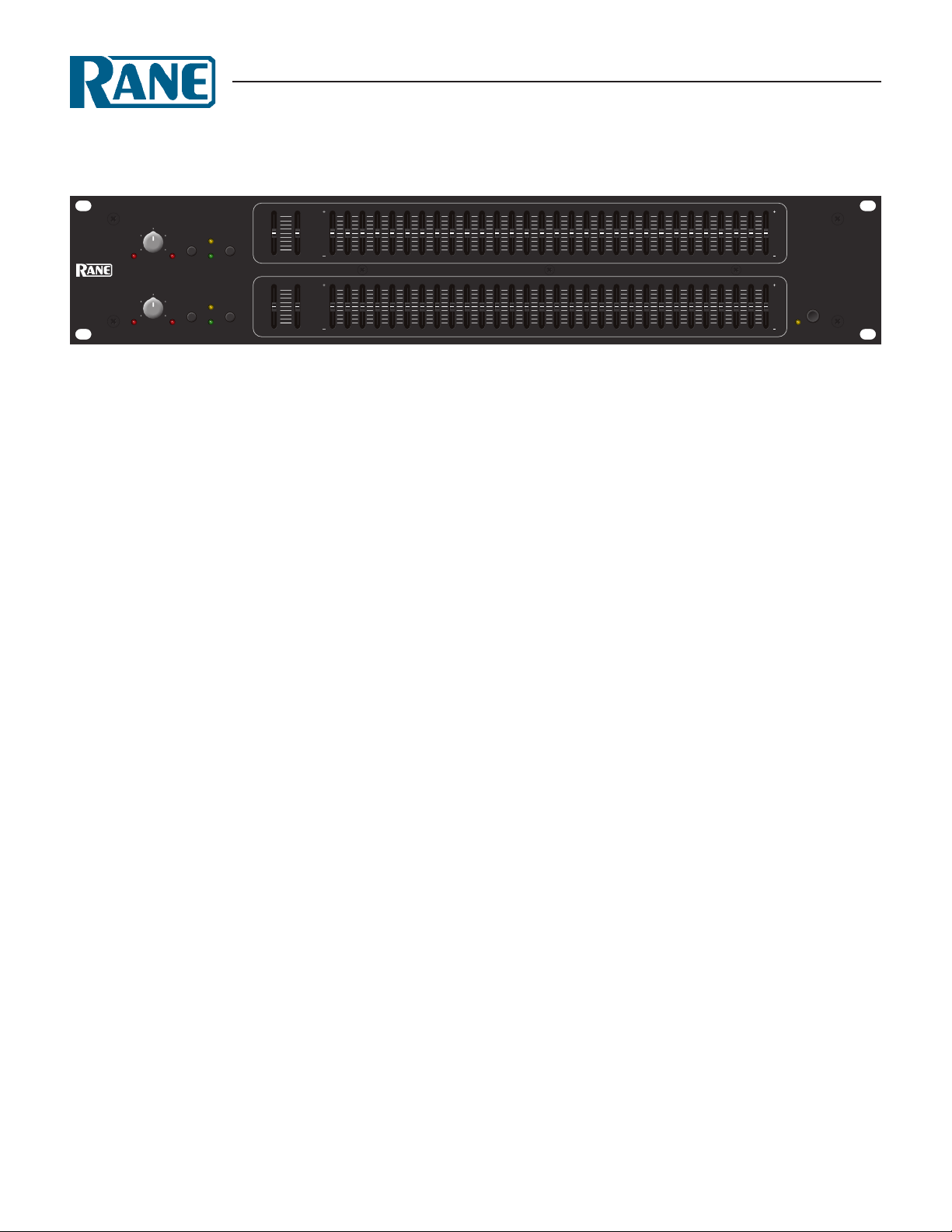
ME 60S
microGRAPHIC EQUALIZER
HIGHLOW
CHANNEL 1
6
248
100
OL LEVEL RANGEBYPASS
CHANNEL 2
6
248
100
OL LEVEL RANGEBYPASS
250 3k
150
±12
±6
±12
±6
40
15
10
CUT FILTERS
250 3k
150
40
15
10
CUT FILTERS
6
•
5k
3
•
10k
0
•
30k
3
•
40k
6
HIGHLOW
6
•
5k
3
•
10k
0
•
30k
3
•
40k
6
General Description
e Rane ME 60S Stereo Constant-Q Equalizer is a twochannel, ⅓-octave design, housed in a two rack-space unit. It
features a Range switch for high slider resolution in the ±6 dB
mode, equivalent resolution to 45 mm sliders found on larger
models. e ±12 dB mode provides a wide range of control over
system audio.
e ME 60S evolved by combining two ME 30 equalizers
in one unit and then embellishing with two adjustable bandlimiting lters on the low and high end. ough consuming only
12 watts of power, a Power switch is added to the ME 60S (the
ME 30S consumes 7 watts and does not have a Power switch).
e active lter sections feature Rane’s innovative constant-Q
(constant bandwidth) design. Constant-Q means the bandwidth
of each individual lter is guaranteed to be narrow enough to
prevent unwarranted interaction between lters, yet wide enough
to produce exactly the type of correction curve demanded
by even the most unusual acoustic surroundings. is diers
dramatically from conventional designs of the past, encumbered
with the unfortunate characteristic of changing bandwidth when
changing boost/cut amounts.
40031.525 40 6350 10080 160125 250200 315 12.5k1k630500 800 1.6k1.25k 2k 3.15k2.5k 5k4k 8k6.3k 10k 20k16k
40031.525 40 6350 10080 160125 250200 315 12.5k1k630500 800 1.6k1.25k 2k 3.15k2.5k 5k4k 8k6.3k 10k 20k16k
12
•
6
•
0
•
6
•
12
12
•
6
•
0
•
6
•
12
POWER
ME 60S
MICROGRAPHIC
EQUALIZER
e adjustable lters are useful to band limit the audio
signal. For instance, restricting high frequencies to match the
incoming signal usually produces the most quiet system. And
a common use for the Low Cut Filter is limiting the signal going to 70-volt speaker systems. Often low frequencies saturate
the loudspeaker transformers. Restricting these signals greatly
improves system intelligibility. Full bandwidth use requires positioning both sliders to their lower limits. is eectively removes
the lters and guarantees 20-20 kHz ±0.5 dB performance.
Front panel controls and indicators include an overall rotary
Level control for each channel as well as Overload indicators.
Passive pushbutton Bypass switches feature LED indicators,
avoiding ambiguity by being on when the unit is Bypassed. (A
passive Bypass switch requires no power to operate. is allows
completion of the audio path should power fail in the ME 60S.)
Inputs and Outputs are electronically balanced designs,
capable of unbalanced operation when required. ey accept
and drive all possible signal levels into normal load impedances.
Balanced applications choose between the XLR or ¼" TipRing-Sleeve connectors. Unbalanced sources also may tie to the
ME60S through mono ¼" connectors (no ring connection).
Features
• Constant-Q Bandwidth Design
• Overall Level Controls
• 20 mm Filter Slide Controls
• ±6 dB or ±12 dB Slider Range
• Sweepable Low & High Cut Filters
• Passive Bypass Switches
• Grounded Center Detents at 0 dB
• Infrasonic, Ultrasonic, & RFI Filters
• Fully Balanced XLR Inputs and Outputs
• ¼" TRS Balanced/Unbalanced Inputs and Outputs
• Universal internal switching power supply (100-240 VAC)
Data Sheet-1
ME 60S
microGRAPHIC EQUALIZER
Features & Specifications
Parameter Specication Limit Units Conditions/Comments
Equalizer:
..........Channels Two
..........Bands (2x30) ⅓-Octave ISO Spacing From 25 Hz to 20 kHz
..........Type Constant-Q
..........Accuracy 3 % Center frequency
..........Travel 20 mm Positive grounded center detent
..........Range ±12 or ±6 1 dB Switch selectable
Inputs: Active Balanced/Unbalanced
..........Connectors XLR and ¼" TRS
..........Impedance >20k Balanced 1% Ω
..........Maximum Level +21 1 dBu
Outputs: Active Balanced/Unbalanced
..........Connectors XLR and ¼" TRS
..........Impedance 400 Balanced 200 Unbalanced 1% Ω
..........Maximum Level +21 Balanced +15 Unbalanced 1 dBu 2 kΩ
+19 Balanced +13 Unbalanced 1 dBu 600 Ω
Overall Gain Range O to +8 (Balanced Out) min dB Sliders centered
RFI Filters Yes
Passive Bypass Switches Yes
Overload LED reshold 4 1 dB Below clipping
Low Cut Filter 10-250 Hz, 12 dB/octave 3% Hz Butterworth
High Cut Filter 3k-40 kHz, 12 dB/octave 3% Hz
Frequency Response 20-20 kHz ±0.5 dB
10-40 kHz +0/-3 dB
THD & Noise 0.008 .002 % +4 dBu, 20-20 kHz
IM Distortion (SMPTE) 0.005 .003 % 60 Hz / 7 kHz, 4:1, +4 dBu
Signal-to-Noise Ratio re +20 dBu re +4 dBu 20 kHz noise BW; balanced out
112 96 2 dB Sliders centered, unity gain
Channel Separation 75 3 dB 1 kHz
Common Mode Rejection 46 1 dB 1 kHz
Maximum Power 12 W
Universal Line Voltage 100-240 VAC, 50/60 Hz VAC 12W
Unit: Agency Listing UL/cUL/CE
Unit: Construction All Steel
..........Size 3.5" H x 19" W x 8.5" D (2U) (8.9 cm x 48.3 cm x 21.6 cm)
..........Weight 9 lb (4.1 kg)
Shipping:
..........Size 4.25" x 20.3" x 13.75" (10.8 cm x 52 cm x 35 cm)
..........Weight 12 lb (5.0 kg)
Note: 0 dBu=0.775 Vrms
Data Sheet-2
 Loading...