


OPERATORS MANUAL ME 30B
microGRAPHIC EQUALIZER
QUICK START
If this is your first equalizer, please do yourself and your speakers a favor and read the complete manual. “An ounce of
prevention...,” and all that.
You may use either the 3-pin or ¼" TRS connector for Input or Output. Hook-up is intuitive. Just follow the
silkscreened instructions on the rear of the unit. Polarity convention is per IEC/ANSI/AES standards of pin 2 positive, pin 3
negative and pin 1 shield. The ME 30B does not invert the signal. Only connect one INPUT type per channel. The 3-pin
and ¼" TRS Inputs do not sum. You may, however, use both types of OUTPUTS simultanesously if desired.
Anyone familiar with other graphic equalizers finds the ME 30B just as familiar. Setting curves is as easy as it is on all
Rane graphics thanks to our innovative constant-Q circuitry. If you feel you want more information on setting up your
curves, please read on.
If you are familiar with equalizers, then hook-up, plug-in, turn-on and go!
ME 30B CONNECTION
When first connecting the ME 30B to other components,
leave the POWER switch off until the very last. This gives
you a chance to make mistakes and correct them without
damaging your fragile speakers, ears and nerves.
INPUTS
Both 3-pin and ¼" TRS Inputs are wired in parallel and
are actively balanced. Each works equally well. Choose
strictly from a required hardware point-of-view, there will be
no performance trade-offs. The wiring convention adheres to
American, British and International standards of pin 2 or tip
being hot, pin 3 or ring being return, and pin 1 or sleeve being
shield. Unbalanced operation involves using only pin 2 or tip
as signal, and pin 1 or sleeve as sheild or ground. It is not
necessary to short any inputs to ground—it doesn’t hurt, it’s
just not necessary. Use pin 1, or the shell, for shield ground.
OUTPUTS
The Outputs mimic the Inputs. Balanced output requires
using pin 2 or tip, and pin 3 or ring for the signal. It does not
require pin 1 or shield. The signal exists differentially
between the two balanced leads; ground is not involved. For
hum-free systems ground is used only for shielding.
EXPANDING
Expanding and/or daisychaining the Inputs and Outputs
normally uses the ¼" jacks. Three parallel Input connectors
allows driving a second signal processor or amplifier without
special cabling.
SIGNAL LEVELS
Signal levels from -10 dBV to +4 dBu are considered
normal and within range (at least 20 dB of headroom exists
above these levels). Do not directly connect microphones into
the ME 30B. These require a mic preamp.
Manual-1
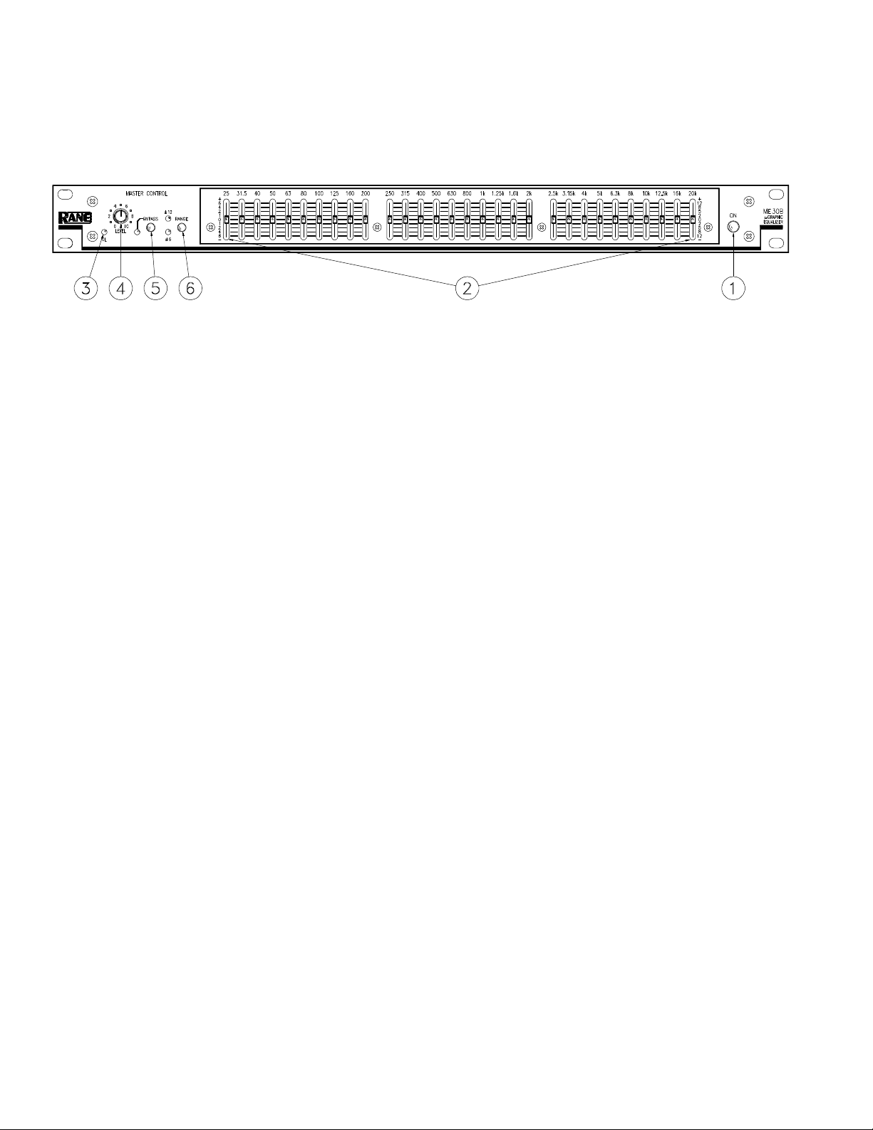
FRONT PANEL DESCRIPTION
1. ON switch: As you have astutely surmised by now, this switch powers up the ME 30B.
2. Filter level slide controls: Each of these sliders controls the output level of each of the bandpass filters. Center position is
grounded for guaranteed flat response.
3. OVERLOAD indicator: This red LED lights up if any section of the ME 30B is within 3 dB of clipping. Occasional
blinking of this LED is acceptable, but if it remains on more than intermittently, turn down either the equalizer’s LEVEL
control or reduce the output level of the preceding component to avoid audible distortion.
4. LEVEL control: This controls the level of signal coming into the ME 30B. Turn this control down if the OverLoad LED
lights up steadily (meaning too strong an Input signal). Since actual unity gain depends on varying slider settings (which is
why we have not marked a unity gain position on the front panel), use the BYPASS switch to determine the exact unity gain
position of this LEVEL control by comparing EQ and BYPASS volumes.
5. BYPASS switch: When the red LED is lit, this indicates that the unit is in the BYPASS mode: signal is routed directly from
the Input to the Output without passing through any active circuitry (often referred to as “hard-wire bypass”). Use this
switch to compare equalized and unequalized material, or to bypass the EQ section in the event of power loss or unit failure.
6. Filter RANGE switch: The gain range of the filter sliders is switchable (as a group) from ±6 dB for high resolution, to
±12 dB for maximum boost/cut capability.
Manual-2

REAR PANEL DESCRIPTION
1. 3-pin INPUT jack: This accommodates balanced signals. Rane adheres to the international and U.S. standard for balanced
pin configurations: Pin 1 is chassis ground (neutral), pin 2 is hot (positive), and pin 3 is signal return (negative). Choose
between this and the ¼" TRS Input jack—use only one—they do not sum.
2. ¼" TRS INPUT jack: This is a TRS (tip-ring-sleeve) ¼" jack accommodating either balanced or unbalanced signals. For an
unbalanced signal use a mono ¼" plug (single conductor with shield). For a balanced signal use microphone cable (two
conductor with shield) with a TRS ¼" plug. Choose between this and the ¼" TRS Input jack—use only one—they do not
sum. Refer to the included RaneNote, “Sound System Interconnection” for unbalanced wiring.
3. 3-pin OUTPUT jack: This balanced output is wired per AES standards of pin 2 “hot”, as described above in (1).
4. ¼" TRS OUTPUT jack: This is a TRS (tip-ring-sleeve) ¼" balanced jack compatible with either balanced or unbalanced
systems. For balanced systems, use a microphone cable wired with pin 1 is chassis ground (neutral), pin 2 is hot (positive),
and pin 3 is signal return (negative). Refer to the RaneNote, “Sound System Interconnection” for unbalanced wiring.
IMPORTANT NOTE
CHASSIS GROUNDING
If after hooking up your system it exhibits excessive
hum or buzzing, there is an incompatibility in the
grounding configuration between units somewhere. Your
mission, should you accept it, is to discover how your
particular system wants to be grounded. Here are some
things to try:
1. Try combinations of lifting grounds on units that
are supplied with ground lift switches or links.
2. If your equipment is in a rack, verify that all
chassis are tied to a good earth ground, either through the
line cord grounding pin or the rack screws to another
grounded chassis.
3. Units with outboard power supplies do NOT ground
the chassis through the line cord. Make sure that these
units are grounded either to another chassis which is earth
grounded, or directly to the grounding screw on an AC
outlet cover by means of a wire connected to a screw on
the chassis with a star washer to guarantee proper contact.
Manual-3

OPERATING INSTRUCTIONS
Insuring the proper level of gain though the ME 30B is
just as important as adjusting the equalizer bands. Improper
gain distribution is a common cause of loss of system headroom and less than optimum noise performance.
The OVERLOAD LED informs of an imminent or passed
overload to the equalizer. Occasional blinking of the OL with
program source material is fine, indicating optimized signalto-noise performance of the ME 30B. Run the ME 30B with
an input signal that is as hot as possible without the OL
lighting more than occasionally.
The BYPASS switch allows comparison of equalized
versus un-equalized signal. It is also useful in adjusting the
level of the ME 30B for unity gain and best signal-to-noise
performance. The gain of the ME 30B is optimized when
there is no sound level difference between the bypassed and
the active positions.
The overall gain range of the level control for the ME 30B
is off to +6 dB for unbalanced operation, or off to +12 dB for
balanced operation. The level difference between the equalizer in bypass or active can be significant. Adjust the LEVEL
control so the signal level is the same between the bypassed
and active positions of the BYPASS switch.
GETTING STARTED
Here is one method of setting your equalizer that works
well. Begin with the following settings:
1. Engage the BYPASS switch. (switch depressed, BYPASS
LED on.)
2. Put all sliders in their center position (0 dB). The center
position has a grounded detent.
3. Position the CHANNEL LEVEL controls about “6” for
unbalanced operation and “7” for balanced operation.
4. Apply a signal to the system.
5. Verify the OL LED is not on—occasionally blinking
during extreme peaks indicates an optimal setting. But if it
lights up a lot or lights steadily, lower the output level of
the previous device in the signal chain.
6. Release the BYPASS switch and begin adjusting the
equalizer filters.
7. During filter band adjustments, if the OL LED lights more
than occasionally, turn down the output of the previous
device in the signal chain.
8. Once all filter bands are adjusted to your liking, compare
the signal loudness with the equalizer bypassed and active.
Adjust the CHANNEL LEVEL controls on the ME 30B
so there is no difference between the levels of bypassed
versus active.
9. The last step is to reconfirm that the OL LED lights only
when there are large signal spikes in the program material,
as in step 5 above.
For insight into how to use an equalizer, to alleviate
acoustic problems or to adjust the overall tone of the program
material, please read the following two sections.
ACOUSTIC COMPENSATION
A graphic equalizer may be used to correct many acoustic
problems. However, one should fully understand the ramifications of doing so. Acoustic problems are generally not
consistent across the entire area of sound coverage. This is
much more of a problem when setting up a sound system for
large venues. In a typical large room or hall, there will be
areas that have acoustic reinforcement problems and other
areas where certain frequencies are almost entirely canceled
out. Try to seek an acoustic remedy for acoustic problems
whenever possible. When this is not possible or feasible, an
equalizer may be used to compensate for an acoustic problem.
But the problem is only improved at the point where the
measurement is taken, other locations in the room may be
adversely affected by the equalizer setting. For this reason,
measure the acoustic response of the system from several
locations and average the equalizer’s setting. Doing this helps
most locations in the venue to have an equal sound quality.
The best way to “see” what the acoustic signature of the
room is doing to sound is to use a real time analyzer or any of
the many computerized measurement systems. Using these
devices to analyze the response of the room and the sound
system is the only accurate means available for setting an
equalizer properly.
Equalization can be like spice in the hands of a master
chef. A little goes a long way in improving sound quality, too
much and the mix is spoiled. If modest amounts of equalization (6-8 dB) do not solve the problem, it is best remedied by
other means. Avoid adding large amounts of boost below 63
Hz, especially when using vented bass cabinets. Boosting
frequencies below the vented enclosure’s low frequency
cutoff can easily cause over excursion of the speaker’s cone,
causing premature failure. In addition, boosting low frequencies can make your power amplifier run hotter, leading to
premature amplifier failure.
When equalizer adjustment is completed, compare the
unequalized sound with the equalized sound by alternately
engaging the BYPASS switch. Use familiar source material
and walk around in the sound coverage area to insure that no
anomalies have been introduced into the sound system. If it
sounds good, you’re done.
TONE CONTOURING
If a ME 30B is used for tone contouring by ear, be careful
about adding upper bass (63 Hz to 200 Hz) as this can cause
“muddiness” or loss of definition. (Also see the previous
warning about boosting frequencies below 63 Hz.) Middle
frequency problems usually express themselves by vocals
having a nasal quality (too much mid band boost) or vocals
not being easily understandable (usually caused by mid band
frequencies being under represented in the overall sound).
High band problems show as “sizzle”— not good, and is
sometimes caused by too much high frequency boosting. This
is most obvious with cymbals and hi-hats. To use the cooking
metaphor, high frequencies should simmer, not sizzle.
©Rane Corporation 10802 47th Ave. W., Mukilteo WA 98275-5098 TEL (425)355-6000 FAX (425)347-7757 WEB http://www.rane.com
All features & specifications subject to change without notice. OCT95
Manual-4

RISK OF ELECTRIC SHOCK
DO NOT OPEN
CAUTION
IMPORTANT SAFETY INSTRUCTIONS
1. Read these instructions.
2. Keep these instructions.
3. Heed all warnings.
4. Follow all instructions.
5. Do not use this apparatus near water.
6. Clean only with a dry cloth.
7. Do not block any ventilation openings. Install in accordance with manufacturer’s instructions.
8. Do not install near any heat sources such as radiators, registers, stoves, or other apparatus (including ampliers) that produce heat.
9. Do not defeat the safety purpose of the polarized or grounding-type plug. A polarized plug has two blades with one wider than the other. A grounding-type plug has two blades and a third grounding prong. e wide blade or third prong is provided for your safety. If the provided plug does not
t into your outlet, consult an electrician for replacement of the obsolete outlet.
10. Protect the power cord and plug from being walked on or pinched particularly at plugs, convenience receptacles, and the point where it exits from
the apparatus.
11. Only use attachments and accessories specied by Rane.
12. Use only with the cart, stand, tripod, bracket, or table specied by the manufacturer, or sold with the apparatus. When a cart is used, use caution
when moving the cart/apparatus combination to avoid injury from tip-over.
13. Unplug this apparatus during lightning storms or when unused for long periods of time.
14. Refer all servicing to qualied service personnel. Servicing is required when the apparatus has been damaged in any way, such as power supply
cord or plug is damaged, liquid has been spilled or objects have fallen into the apparatus, the apparatus has been exposed to rain or moisture, does
not operate normally, or has been dropped.
15. e plug on the power cord is the AC mains disconnect device and must remain readily operable. To completely disconnect this apparatus from
the AC mains, disconnect the power supply cord plug from the AC receptacle.
16. is apparatus shall be connected to a mains socket outlet with a protective earthing connection.
17. When permanently connected, an all-pole mains switch with a contact separation of at least 3 mm in each pole shall be incorporated in the electrical installation of the building.
18. If rackmounting, provide adequate ventilation. Equipment may be located above or below this apparatus, but some equipment (like large power
ampliers) may cause an unacceptable amount of hum or may generate too much heat and degrade the performance of this apparatus.
19. is apparatus may be installed in an industry standard equipment rack. Use screws through all mounting holes to provide the best support.
WARNING: To reduce the risk of re or electric shock, do not expose this apparatus to rain or moisture. Apparatus shall not be exposed to dripping
or splashing and no objects lled with liquids, such as vases, shall be placed on the apparatus.
NOTE: is equipment has been tested and found to comply with the limits for a Class B digital device, pursuant to part 15 of the FCC Rules. ese
limits are designed to provide reasonable protection against harmful interference in a residential installation. is equipment generates, uses and can
radiate radio frequency energy and, if not installed and used in accordance with the instructions, may cause harmful interference to radio communications. However, there is no guarantee that interference will not occur in a particular installation. If this equipment does cause harmful interference to
radio or television reception, which can be determined by turning the equipment o and on, the user is encouraged to try to correct the interference
by one or more of the following measures:
• Reorient or relocate the receiving antenna.
• Increase the separation between the equipment and receiver.
• Connect the equipment into an outlet on a circuit dierent from that to which the receiver is connected.
• Consult the dealer or an experienced radio/TV technician for help.
CAU TIO N: Changes or modications not expressly approved by Rane Corporation could void the user's authority to operate the equipment.
is Class B digital apparatus complies with Canadian ICES-003.
Cet appareil numérique de la classe B est conforme à la norme NMB-003 du Canada.
WARNING
To reduce the risk of electrical shock, do not open the unit. No user
serviceable parts inside. Refer servicing to qualied service personnel.
e symbols shown below are internationally accepted symbols that warn
of potential hazards with electrical products.
is symbol indicates that a dangerous voltage
constituting a risk of electric shock is present within
this unit.
is symbol indicates that there are important
operating and maintenance instructions in the
literature accompanying this unit.
 Loading...