

Page 1
DATA S HE ET
General Description
The MA 3 is a three-channel amplifier designed to operate
reliably in commercial environments. The MA 3 was specifically designed for use in:
• Paging
• Foreground Music
• Background Music Distribution
and with the Rane family of paging, foreground music, and
background music products, such as the Rane CP series.
Each channel of the MA 3 delivers 40 watts of continuous
average power into 8 ohms and 60 watts into 4 ohms. Up to
three optional 40 watt, 70.7 volt or 100 volt constant-voltage
audio transformers may be installed inside the MA 3, eliminating the need for external wiring or transformer mounting.
See the TF 407 / TF 410 data sheet for more information.
The MA 3 uses a conventional linear power supply with
toroidal transformer. This configuration minimizes the
emissions associated with switching supplies and noisier
transformer designs. The power supply features independent
secondary supplies for each channel, minimizing load
regulation interaction and crosstalk.
Thermal management is accomplished with a sealed heattunnel design incorporating low velocity forced air and large
aperture openings. This design minimizes the noise usually
associated with forced air cooling and eliminates the need for
an air filter. Forced air cooling allows the amplifier to operate
reliably in harsh environments and avoid the buildup of heat
MA 3
MULTICHANNEL AMPLIFIER
in unventilated racks associated with passive convection
cooling.
The combination of a solid, conservative power supply
and forced air cooling allows the MA 3 to simultaneously
deliver 60 watts of continuous-average-power to all three
channels.
SPiKe®* dynamic protection circuitry completely safeguards each channel against over-voltage, under-voltage,
overloads, transients from inductive loads, thermal runaway
and instantaneous temperature peaks. Biasing is not allowed
to occur when an under-voltage condition exists, reducing
turn on and turn off transients.
Fast-response limiters allow the MA 3 to tolerate up to 20
dB of overdrive into 8 and 4 ohm loads while holding THD
below 1%. This means no loss of speech intelligibility or
harsh clipping. This feature greatly increases the dynamic
range of the system without external limiters.
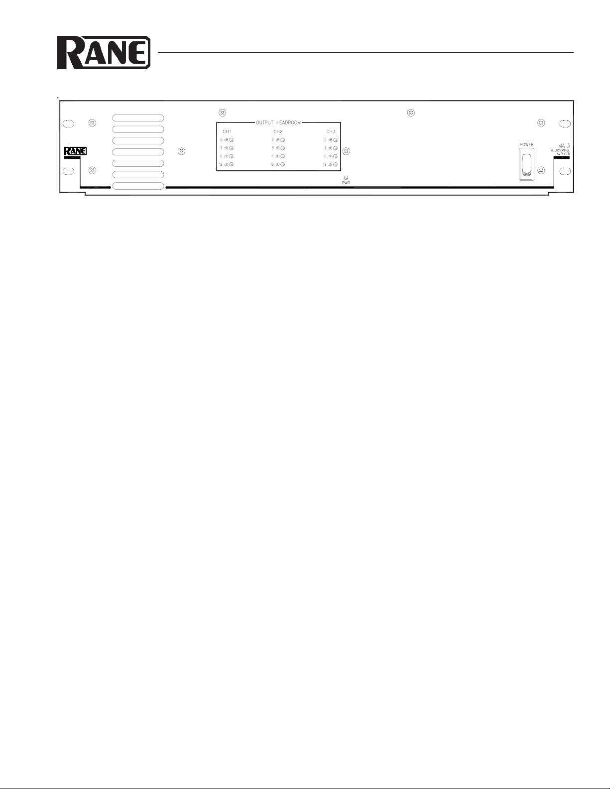
Peak-responding, load-adaptive meters accurately indicate
the remaining headroom. The meters are helpful in setting
system levels and indicating signal compression.
Balanced inputs with Euroblock connectors are provided.
Euroblock output connectors accept up to 12 gauge wire. Rear
panel Level controls allow amplifier sensitivity adjustment.
Internally selectable 80 Hz highpass filters offer protection
against over excursion of small bookshelf speakers and
saturation of distribution transformers at low frequencies.
Features
• 3 Independent Amplifiers
• 60W / Ch. Continuous Average Power into 4 ohms 20-20k Hz
• 40W / Ch. Continuous Average Power into 8 ohms 20-20k Hz
• Load Sensitive Dynamic Limiters
• Load Sensitive Headroom Meters
• SPiKe® Protection Circuitry
• High Capacity Linear Power Supply
*SPiKe is a registered trademark of National Semiconductor Corporation.
• Sealed Heat-Tunnel Forced Air Cooling
• Input Level Controls (on rear panel)
• 80 Hz High Pass Filter Selection
• Euroblock Connectors
• IEC Socket and Line Cord
• Three Optional Internal 70.7 V or 100 V Distribution Transformers
• UL/cUL Certification
Data Sheet-1
Page 2

MA 3
MULTICHANNEL AMPLIFIER
Features and Specifications
Parameter Specification Limit Units Conditions/Comments
Input: Euroblock Connecto r
Impedance 20k min. ohms Each leg
Maximum Input Level +20 min. dBu
Sensitivity Off to 0 dBu Input required for full power; 8 ohms
CMR 40 min. dB 20 Hz to 20 kHz
Highpass Filter 80 Hz (switchable) ±2.5% Hz 2nd-order butterworth
Amplifier: Gain
Power Output 40/60 min. watts 8/4 ohms cont. avg. power, all ch. driven
Frequency Response 20 - 20k +0,-.5dB Hz
S/N 90 min. dBr re: 40W, 8 ohms, A-weighted
Crosstalk -60 max. dB 1 kHz, 4 ohms, all channels driven
THD+N 0.05% typ. 1 kHz, 40W, 8 ohms, 80 kHz BW
Slew Rate 10 min. V/ µs
Damping Fact or 80 m in. 8 ohms, 1 kHz
On/Off Transient Muting Active Drop out 85 VAC (120V unit)
Fan Cooling Active Constant-Current Sealed tunnel, 2-speed
Tunnel Power Dis sipation 120W; 410 BTU/hr 60 W/ch.; 4 ohm load; all channels driven
SOA SPiKe* Safe Operating Area
Limiter: Attack Time 10 typ. ms 10 dB step
Decay Time 3000 typ. ms 10 dB step
Threshold 0.1% THD+N typ. @1 kHz
Action 1% THD+N max. 15 dB overdr ive (max. level) @ 1 kHz
Meter: Attack Time 20 typ. ms 10 dB step
Decay Time 500 typ. ms 10 dB step
Indicators 0, 3, 6 ,12 +0, -2 dB 20log (V
Supply: Type Linear; Toroidal Transformer Independent secondaries for each channel
Line Voltage 120/230 VAC Internal selection
Power Consumption 33.6W; 115 BTU/hr No load (idle)
Total Load & Unit 360W; 1200 BTU/hr 60 W/ch.; 4 ohm load; all channels driven
Optional Transformers:
Insertion Loss 0.5 typ. dB Installs internally, 1 per channel, up to 3
Unit: Agency Listing
..........120 VAC model UL UL 6500
..........Construction All Steel
..........Size 3.5"H x 19"W x 9"D (2U) (8.9 cm x 48.3 cm x 22.9 cm)
..........Weight 26 lb (11.8 kg)
Shipping: Size 4.25" x 20.3" x 13.75" (11 cm x 52 cm x 35 cm)
..........Weight 30 lb (13.6 kg)
27 ±0.5 dB 1 kHz
0.1% typ. 1 kHz, 60W, 4 ohms, 80 kHz BW
0.2% typ. 20 Hz-20 kHz, 35W, 8 ohms, 80 kHz BW
MAX/VOUT
40 typ. watts 50 Hz to 15 kHz ±1 dB
cUL (Canada) C22.2
) or 10log (P
MAX/POUT
)
*SPiKe is an acronym for S
Note: 0 dBu = 0.775 Vrms
Data Sheet-2
elf Peak Instantaneous temperature (Ke ) protection circuitry.
Page 3

Block Diagram
T
T
T
CH1 INPUT
CH2 INPUT
80 Hz HP
80 Hz HP
OUT
IN
OUT
IN
CH1 LEVEL
SERVO
LIMIT
CH2 LEVEL
SERVO
LIMIT
VCA
VCA
HEADROOM METER
AMP
MUTE
HEADROOM METER
AMP
MUTE
MA 3
MULTICHANNEL AMPLIFIER
0 dB
3 dB
6 dB
12 dB
TRANSFORMER
OPTION
CH1 OUTPU
40 W/8 ohms
60 W/4 ohms
0 dB
3 dB
6 dB
12 dB
TRANSFORMER
OPTION
CH2 OUTPU
40 W/8 ohms
60 W/4 ohms
CH3 LEVEL
CH3 INPUT
OUT
IN
80 Hz HP
SERVO
LIMIT
DC FAN
FAN
DRIVE
FAST
NORMAL
Examples
Two-Channel Direct Drive Left & Right, Third Channel Distributes
with Internal Constant-Voltage Transformer
VCA
HEADROOM METER
0 dB
3 dB
6 dB
12 dB
TRANSFORMER
AMP
MUTE
OPTION
All Three Channels Distributed to Independent Zones
CH3 OUTPU
40 W/8 ohms
60 W/4 ohms
Data Sheet-3
Page 4

MA 3
MULTICHANNEL AMPLIFIER
Rear Panel
Architectural Specifications
The MA 3 shall be a three channel amplifier. It shall
deliver 40 watts continuous average power into 8 ohms and
60 watts continuous average power into 4 ohms. The amplifier shall have balanced inputs with Euroblock connectors and
Euroblock output connectors capable of accepting 12 gauge
wire. Input level controls shall allow adjustment of input
sensitivity. An internal means of selecting 80 Hz highpass
2nd-order Butterworth filters shall be provided. Load sensitive
limiter circuits shall expand the dynamic range of the amplifiers and prevent clipping and the associated loss of speech
intelligibility.
The power supply shall use a conventional linear supply
with means of operating from 120 VAC 50/60 Hz or 230
VAC 50 Hz. An IEC connector with integral fuse and IEC
cord shall be utilized. A front panel mounted power switch
shall be provided with “power-on” indicator.
Thermal management shall employ forced air cooling,
allowing the amplifiers to operate reliable in unventilated
racks at elevated ambient temperatures. The design shall
incorporate a sealed heat tunnel with large aperture openings
and low velocity air flow to minimize noise and eliminate the
need for air filtering and the associated maintenance.
The design shall provide protection against overvoltage,
undervoltage, overloads, transients from inductive loads,
thermal runaway and instantaneous temperature peaks. Load
sensitive headroom meters shall provide indication of 0, 3, 6
and 12 dB of remaining headroom.
The main chassis shall be constructed of 12 gauge, coldrolled steel capable of reliably supporting rack mount
applications. There shall be a means of installing up to three
40W, 70.7V (or 100 volt) constant-voltage distribution
transformers inside the amplifier with quick connect terminals.
120 VAC unit shall be UL listed and cUL certified.
The unit shall be a Rane Corporation Model MA 3.
Available Accessories
• TF 407: 40W, 70.7V Distribution transformer
• TF 410: 40W, 100V Distribution transformer
Both transformers rated 40 watts, 50 Hz to 15k Hz ±1 dB, with 0.5 dB Insertion loss.
Up to 3 mount inside the MA 3.
©Rane Corporation 10802 47th Ave. W., Mukilteo WA 98275-5098 TEL (425)355-6000 FAX (425)347-7757 WEB http://www.rane.com
Data Sheet-4
All features & specifications subject to change without notice. DOC 105226 PN 10158
 Loading...