

Page 1
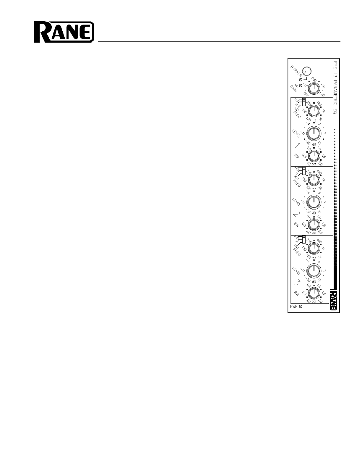
OPERATING / SERVICE MANUAL FPE 13
PARAMETRIC EQUALIZER
QUICK START
No one likes to read manuals. Everyone likes to plug in and turn on. That’s usually OK, and
with a very few exceptions, damage is unlikely to result from such procedures with the FPE 13.
If you are using the FPE 13 in an insert loop of a mixer, hook-up is extremely easy. Simply
connect them together using a single stereo cable (¼" TRS) between the mixer’s insert loop and
the FPE 13’s PATCH I/O jack. This jack is wired for the tip=send, ring=return convention used
by mixer manufacturers.
Anyone familiar with other parametric equalizers will find this one very similar. One word
of caution: the FREQ range switches can drastically change the center frequency of a given
filter. A range of 10Hz to 20kHz may be achieved with the proper operation of the switches and
the FREQ sweep control. If full boost is applied with a filter LEVEL control and a change is
made in the setting of the FREQ range switch, disastrous results may occur. BE CAREFUL.
To operate the filters, set the range switch for the desired mulitple frequency band, set the
BW (bandwidth) control for the desired bandwidth and then boost or cut the desired amount
using the filter LEVEL control.
Never connect anything except AN APPROVED RANE POWER SUPPLY TO THE THING THAT LOOKS
LIKE A TELEPHONE JACK ON THE REAR OF THE FPE 13. This is an AC input and requires special
attention if you do not have an operational power supply exactly like the one that was originally
packed with your unit. See the full explanation of the power supply requirements elsewhere in
this manual.
SYSTEM CONNECTION
When connecting the FPE 13 to other components in your
system for the first time, leave the power supply for last. This
will give you a chance to make mistakes and correct them
before any damage is done to your fragile speakers, ears and
nerves.
INPUTS on the FPE 13 are balanced. This means that
standard 3-pin (XLR) connectors on the ends of any good
quality cable will work well between your other signal
processing and amplification gear. As with all Rane products,
pin 2 is used for “hot” or “+” signal polarity, pin 3 is “return”
or “–” and pin 1 is signal ground. If unbalanced operation is
required, wire your connector so that pins 1 and 3 are shorted
together and drive your unbalanced signal into pin 2. Then
use the combination of 1 and 3 for signal ground/return. You
may use either pin 1 or case for shield ground. (See Rane
Note 110 for further information on this subject).
OUTPUTS. The FPE 13’s Outputs are balanced as well.
Again, pin 2 is hot and pin 3 is not. Pin 1 is signal ground.
True balanced operation requires only the use of pins 2 and 3
for signal and either case ground (chassis) or pin 1 signal
ground for shielding. If unbalanced output is your preference,
use pin 2 as signal and pin 1 as return. Use case ground for
shield. Again, have a look at Rane Note 110 for more detail.
EXPANDING the Inputs and
Outputs has been accommodated
with ¼" jacks whose tip is connected
to pin 2 of the 3-pin connectors, ring
is connected to pin 3 and sleeve is
connected to pin 1. These ¼" jacks
may be used for primary Inputs and
Outputs should you wish to do so.
These connectors may also be used
for daisychaining the Inputs so more
than one processor can be driven from a single source, but
only one is an Input; they do not sum. The second Output
connector may be used to drive a second processor or
amplifier without special cabling.
PATCH I/O to channel inserts on most mixers has been
made very simple. Connecting a shielded stereo tip-ringsleeve (TRS) cable between the FPE 13’s PATCH I/O and a
TRS insert on your console implements this feature.
SIGNAL LEVELS applied to the FPE 13 may cover a
broad dynamic range. This device has been optimized to
operate perfectly with all signal processing and amplification
gear. The only signal level problems encountered will be with
very low level sources, such as microphones. Do not directly
connect mic levels into the FPE 13. Use a mic preamp first.
Page 2
FRONT PANEL DESCRIPTION
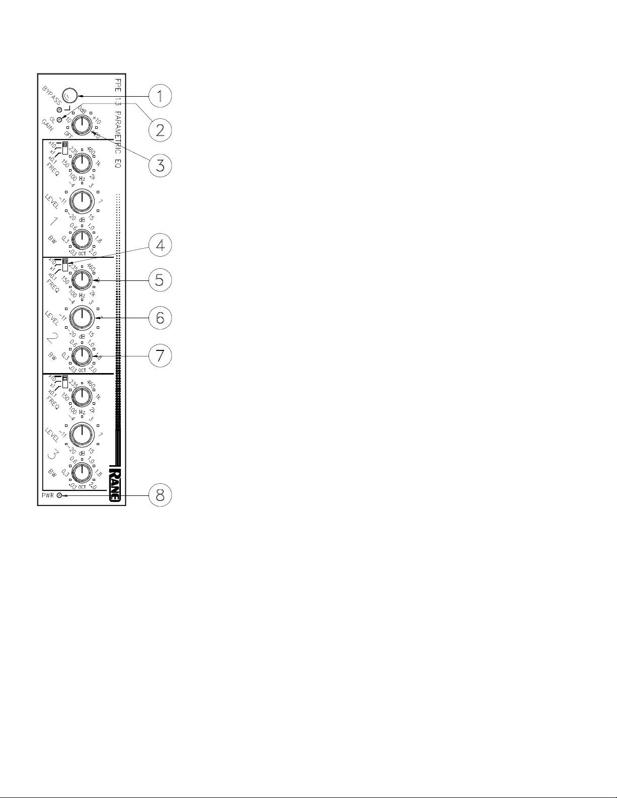
1. OVERALL BYPASS SWITCH & INDICATOR. This pushbutton switch activates
the “hard-wire” bypass function. When in its in position, all three pins of the Input
connector(s) are directly connected to the same pins on the Output connector(s) and
the red LED lights. Engaging this switch converts the FPE 13 to a relatively expensive patch cord with pretty lights.
2. MASTER OVERLOAD INDICATOR. This red LED illuminates whenever the
input, output, or any of the three parametric filters exceeds a level of 4dB below
clipping. Occasional flickering is normal; however, it should not be allowed to light
steadily.
3. INPUT GAIN CONTROL. This rotary control increases INPUT gain as it is rotated
clockwise. Its range is from OFF at full CCW rotation to +20dB at full CW.
4. FREQUENCY RANGE SWITCH. The calibrations on this three position switch
indicate the factor by which the frequency calibrations of the Frequency sweep
control (5) should be multiplied. For instance, if the range switch is in the “x0.1”
position and the sweep knob is at 460, then the actual center frequency of the filter is
46Hz. The proper operation of this switch in conjunction with the sweep control
yields a range of 10Hz to 20kHz.
5. FREQUENCY SWEEP CONTROL. This rotary control increases the center
frequency of its filter as it is rotated clockwise. It is calibrated from 100 to 2k, and its
exact frequency is determined by the range switch described in (4), above.
6. FILTER LEVEL CONTROL. This rotary control determines the amount of boost
or cut applied to the FPE’s passband by its filters. The center detent, cleverly placed
at the center of rotation of this control, provides a ground for the filter which completely eliminates the filter’s influence over FPE 13 operation. Rotating this knob
clockwise increases the gain at the center frequency of the filter, CCW from center
decreases the gain at said center frequency.
7. FILTER BANDWIDTH CONTROL. Calibrated from .03 octaves to 2.0 octaves,
this rotary control adjusts the “width” of coverage of each filter. .03 octave (1/30
octave) will yield the narrowest coverage. Bandwidths this narrow are normally
reserved for notch feedback control. Higher settings yield smoother curves and are
convenient for program sweetening and acoustic compensation.
8. POWER LIGHT. This yellow LED illuminates any time power is supplied to the
FPE 13 from a Rane RS 1 or VC 18 single power supply, RAP 10 or FRS 8 multiple
power supply. Other power sources could conceivably cause illumination of the LED
and several ICs and resistors inside.
Page 3

REAR PANEL DESCRIPTION
1. 3-pin INPUT Connector. Pin 2 is positive, pin 3 is negative and pin 1 is signal
ground. For unbalanced operation, use pin 2 as hot and pin 1 as return.
2. INPUT Expand Connector. This ¼" TRS connector parallels the 3-pin connector
described in item 1. Tip is positive, Ring is negative and Sleeve is signal ground.
3. Terminal Strip INPUT and OUTPUT. The +, – , and COMMON GND terminals
parallel the respective pins in the 3-pin and ¼" connectors. Used for primary Inputs
and Outputs or additional patch connections. Use #6 spades.
4. OUTPUT Expand Connector. This ¼" TRS connector parallels the 3-pin connector
exposed in item 5 below. As before, Tip is hot, Ring is not and Sleeve is signal
ground.
5. 3-pin OUTPUT Connector. Pin 2 is positive, pin 3 is negative and pin 1 is signal
ground. For unbalanced operation, do not short any pins to any others. Active balanced outputs operated in the unbalanced mode use only pin 2 driving the line and
pin 1 acting as the return. Pin 3 should be left disconnected. Grounding pin 3 will not
cause any damage nor will it impair the sound. It only creates extra work for your
audio electrons and is unnecessary.
6. PATCH I/O Connector. This ¼" TRS jack provides an unbalanced I (Input) on its tip
and an unbalanced O (Output) on its ring. Designed for use with tip=send/ring=return
effect loop inserts found on many mixing consoles. This provides an easy means for
patching the unit into effect loops as painlessly as possible, using a single ¼" TRS
stereo patch cable. CAUTION: Use either the PATCH I/O or any of the INPUT and
OUTPUT connectors—Do not use both at the same time. These are not summing
inputs. Only one at a time may be used.
7. GROUND LIFT Switch. This switch provides the ability to separate chassis ground
and signal ground. Normally, this switch should be in the LIFT position. In some
circumstances, moving it to the opposite position eliminates stubborn hum and buzz
problems. We realize a scientific explanation would be helpful, unfortunately science
doesn’t have enough to do with it. If you are tempted to try moving this switch with
your power amplifiers turned on and up, don't be. Always turn your amplifier levels
down before changing your grounds around and then bring them up slowly. Put a
speaker re-coner out of work today!
8. Remote Power Supply Input. The unit is supplied from the factory with a Model RS
1 Remote Power Supply suitable for connection to this input jack. The power requirements of the unit call for an 18-24 volt AC center-tapped transformer only. It is not a
telephone jack. Never use a power supply other than the one supplied or a replacement approved by Rane Corporation. Using any other type of supply may damage the
unit and void the warranty. Two years parts and labor is worth safeguarding, don’t you
think?
9. Chassis Ground Point. A 6-32 threaded hole used for chassis grounding purposes.
See the CHASSIS GROUNDING note on the last page for details.
Page 4

OPERATING INSTRUCTIONS
Before attempting any equalization of audio with the FPE
13, it is important to optimize the Input GAIN control setting.
Improper gain distribution is a common cause of headroom
loss in audio systems.
The FPE 13 provides you with an overall BYPASS switch
& indicator as well as an OL (overload) LED as useful tools
for optimizing gain set-up. The BYPASS switch is most
useful for making A-B comparisons, i.e., comparing equalized (Bypass out) versus unequalized (Bypass in) sound. To
be able to do this freely, without danger of system damage,
requires you to set the level through the FPE 13 to approximately unity. Failure to do so can produce alarming results.
The gain range of the FPE 13 goes all the way from Off to
+20dB. Quite respectable—and enough rope to hang yourself.
Since the FPE 13 is always unity gain in Bypass, if you add or
reduce Gain (beyond EQ make-up gain) the level differences
between Bypass in/out can be startling. Therefore you want to
set the GAIN control for equal in/out loudness levels.
To get started, make these initial set-up adjustments:
BYPASS Switch “In” (= bypassed condition = red LED on).
GAIN Control Center-Detent Position (unity gain spot).
(3) LEVEL Controls Center-Detent Positions (0dB boost/cut).
Next apply a signal to the system. Their will be no system
gain change because the FPE 13 is in Bypass. Check the OL
indicator to be sure it is not lit. If the OL LED is on, turn
down the GAIN control until it goes out. Note, however, that
the FPE 13 will no longer have unity gain when you switch it
out of Bypass.
If the OL LED is not lit, then the center detent position of
the GAIN control is the ideal place to start. Do not increase
the gain above this point until you do enough cutting with the
EQ controls to warrant adding make-up gain. Use the BYPASS switch to set equal loudness.
Release the BYPASS switch and you are ready to start
equalizing the system. And since feedback and tone contouring are two of the most common uses for equalization, here
are a few words on each.
FEEDBACK may be controlled nicely with a device such
as the FPE 13. With the range switches you may position all
three bands of the equalizer to overlap to remove any acoustic
resonances causing you grief. As luck would have it, the top
few nodes are usually grouped in such a way that you can’t
get them all with a conventional parametric. With the FPE
13’s overlapping bands, you never have this problem.
A good way to find them is to set the bandwidth for about
1/2-octave, the LEVEL control to full cut, then sweep around
with the FREQuency knob until you find the first culprit.
Once you center on the ring frequency, reduce the amount of
cut to a level just below where the feedback comes back.
Then reduce the BandWidth to a point where the feedback
stays dead and the sound quality comes back to life. Something between 1/30 octave and 1/3 octave usually does the
trick.
TONE CONTOURING is accomplished with the FPE 13
mainly by ear. This you know how to do. Be careful, though,
not to introduce too much boost to the upper bass area to
prevent your audience from calling 911. Be aware also that
the FPE 13 is capable of boosting signals up to +15dB—a
level at which great care should be taken to prevent seismic
disturbances.
Happy EQing and have fun.
IMPORTANT NOTE
CHASSIS GROUNDING
The FPE 13 is supplied with a rear-mounted groundlift switch. The unit is shipped with this switch in the
“grounded” position, tying circuit ground to chassis
ground. If after hooking up your system it exhibits
excessive hum or buzzing, there is an incompatibility in
the grounding configuration between units somewhere.
Your mission, should you accept it, is to discover how
your particular system wants to be grounded. Here are
some things to try:
1. Try combinations of lifting grounds on units that
are supplied with ground lift switches or links.
2. If your equipment is in a rack, verify that all chassis
are tied to a good earth ground, either through the line
cord grounding pin or the rack screws to another
grounded chassis.
3. Units with outboard power supplies, such as the
FPE 13, do not ground the chassis through the line cord.
Make sure that these units are grounded either to another
chassis which is earth grounded, or directly to the grounding screw on an AC outlet cover by means of a wire
connected to a screw on the chassis with a star washer to
guarantee proper contact.
Please refer to Rane Note 110 (supplied with your FPE
13 and available on request at no charge if you lost your
first one) for further information on system grounding.
©Rane Corporation 10802 47th Avenue West, Mukilteo WA 98275-5098 TEL(206) 355-6000 FAX(206) 347-7757
All features & specifications subject to change without notice. 520-109 AUG94Printed in the U.S.A. on Recycled Paper
 Loading...