

Page 1
OPERATING / SERVICE MANUAL FMM 42
QUICK START
Operating Manuals! You can’t live with them; you can’t live without them. If you don’t
read them, the damn thing never works right; and if you do read them, you get so confused you
never get it turned on! For you, we present the famous Quick Start section. Read this, and you
get dessert.
If you are using the FMM 42 as a master mixing module, connect the FLEX BUS OUT of
the last mixing module to the FLEX BUS IN on the FMM 42 using the 7-pin DIN patch cable
supplied. Aux bus program is routed through the AUX BUS level controls and then the AUX
BUS LOOP jacks and into the MASTER A/B outputs. Insert your reverb, or any other signal
processing unit, into the BUS LOOPS, by means of the tip=send, ring=return jacks. In addition
to the BUS input, the FMM 42 has a MIC/LINE 1 input and a STEREO LINE 2 input. The
MIC/LINE 1 input is equipped with a Ducking (attenuating) feature, allowing its use as a
priority paging input. This allows voice or other signals to override or attenuate (duck) all other
program routed through the FMM 42. The BUS THRU jack allows routing of the unaltered
Flex bus material to another FMM 42 or other Flex bus equipped module. The FMM 42 may
also be used stand-alone, without any bus inputs, as a straightforward background music/paging
system or the like. In this case the AUX BUS LOOP jacks may be used as additional line inputs
by using special ¼" TRS cables with tip left open, ring as signal hot and sleeve as ground.
NEVER CONNECT ANYTHING EXCEPT AN APPROVED RANE POWER SUPPLY
TO THE RED THING THAT LOOKS LIKE A TELEPHONE JACK ON THE REAR OF
THE FMM 42. This is an AC input and requires special attention if you do not have an
operational power supply EXACTLY like the one that was originally packed with your unit.
See the full explanation of the power supply requirements elsewhere in this manual.
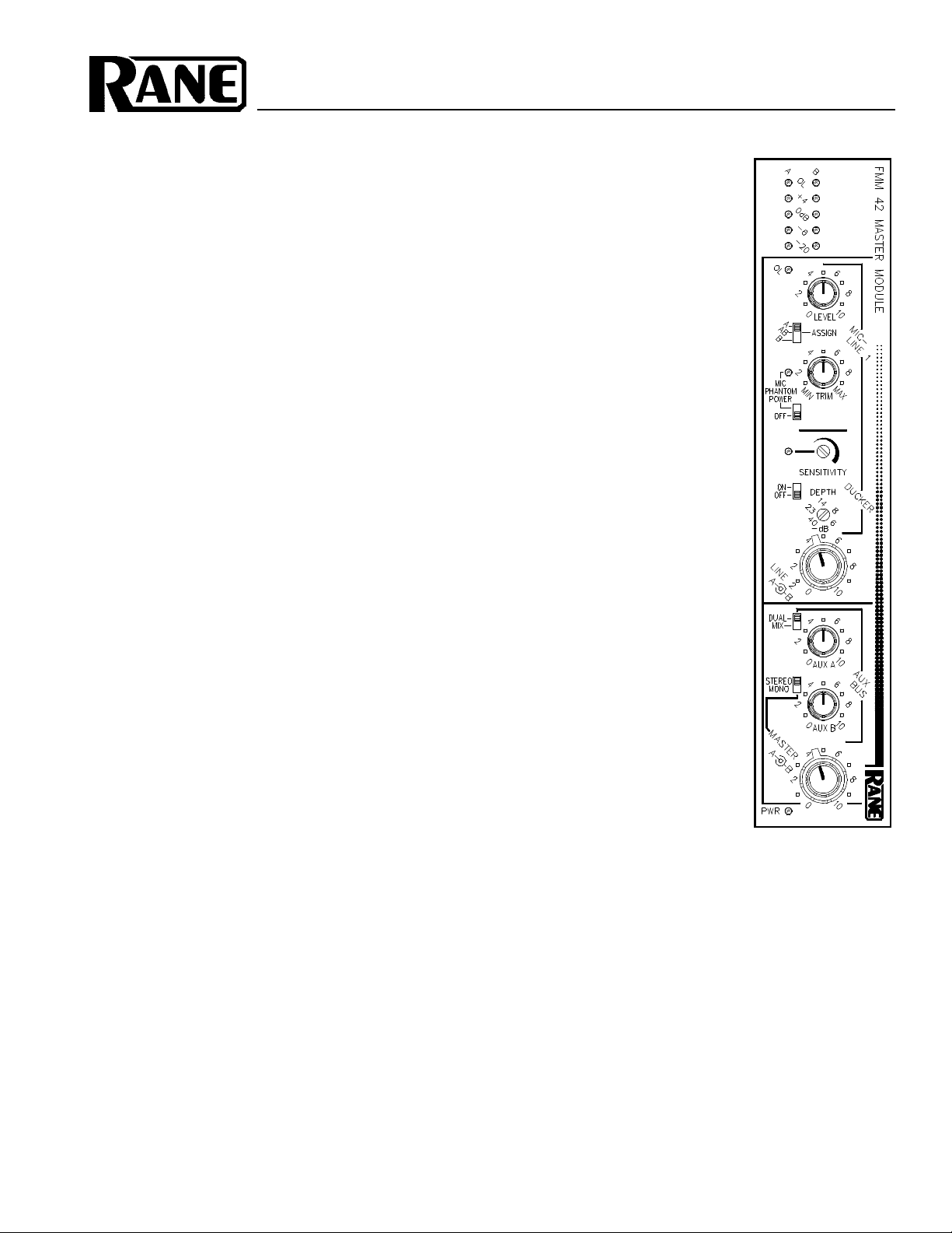
MASTER MODULE
SYSTEM CONNECTION
When connecting the FMM 42 to other components in
your system for the first time, LEAVE THE POWER
SUPPLY FOR LAST. This gives you a chance to make
mistakes and correct them without damage to your fragile
speakers, ears and nerves.
INPUTS. The MIC-LINE 1 INPUT on the FMM 42 is
balanced. This means that standard 3-pin (XLR) connectors
on the ends of any good quality cable work well with the
FMM 42 and a microphone of your choice. In compliance
with American, British and International standards, pin 2 is
used for “hot” or “+” signal polarity, pin 3 is “return” or “–”
and pin 1 is signal ground. For unbalanced inputs, drive pin
2 as hot and pin 1 as ground. It is not necessary to short pin
3 to ground on Flex series microphone inputs; however, it
will not hurt anything, if you do. You may use either pin 1 or
case for shield ground on the 3-pin input. (See Rane Note
110 for further information on this subject). If you are using
the ¼" STEREO LINE 2 input, tip is Channel A, ring is
Channel B and sleeve is ground.
OUTPUTS. The FMM 42’s Master Outputs are balanced. On these outputs, pin 2 is hot (+), pin 3 is return (-)
and pin 1 is signal ground. If unbalanced output is required,
use pin 2 as hot and pin 1 as ground. Do not short any pins to
any others. This is not a transformer balanced output.
BUS INPUTS. The 7-pin DIN
bus connectors are used primarily
with other Flex modules. These are
not MIDI connectors. Use only the
supplied DIN cable. If for some
reason there is not a cable in the
FMM 42 box, please contact Rane
for a replacement. If you are in a
bind, a 5-pin DIN may be used
instead of a 7-pin. The two outside
pins are spares on the FMM 42 and have been included for
possible future compatibility reasons. All pins on the DIN
cable should be wired straight through, i.e., 1 to 1, 2 to 2,
etc.
A typical Flex system using FMM 42s would be where
several FMI 14s are used as input channels, possibly mixed
with a FPM 44 program mixer, all combined with one FMM
42 as the master termination module. In a case like this, the
first FMI 14’s BUS OUT goes to the second’s BUS IN, its
BUS OUT to the third’s BUS IN, and so on down the line.
FPM 44s, FPM 42s, and FLM 82s connect the same way.
The last BUS OUT connects to the FMM 42’s BUS IN. This
sums all input modules properly. See the Flex Users Guide
for additional details.
Page 2
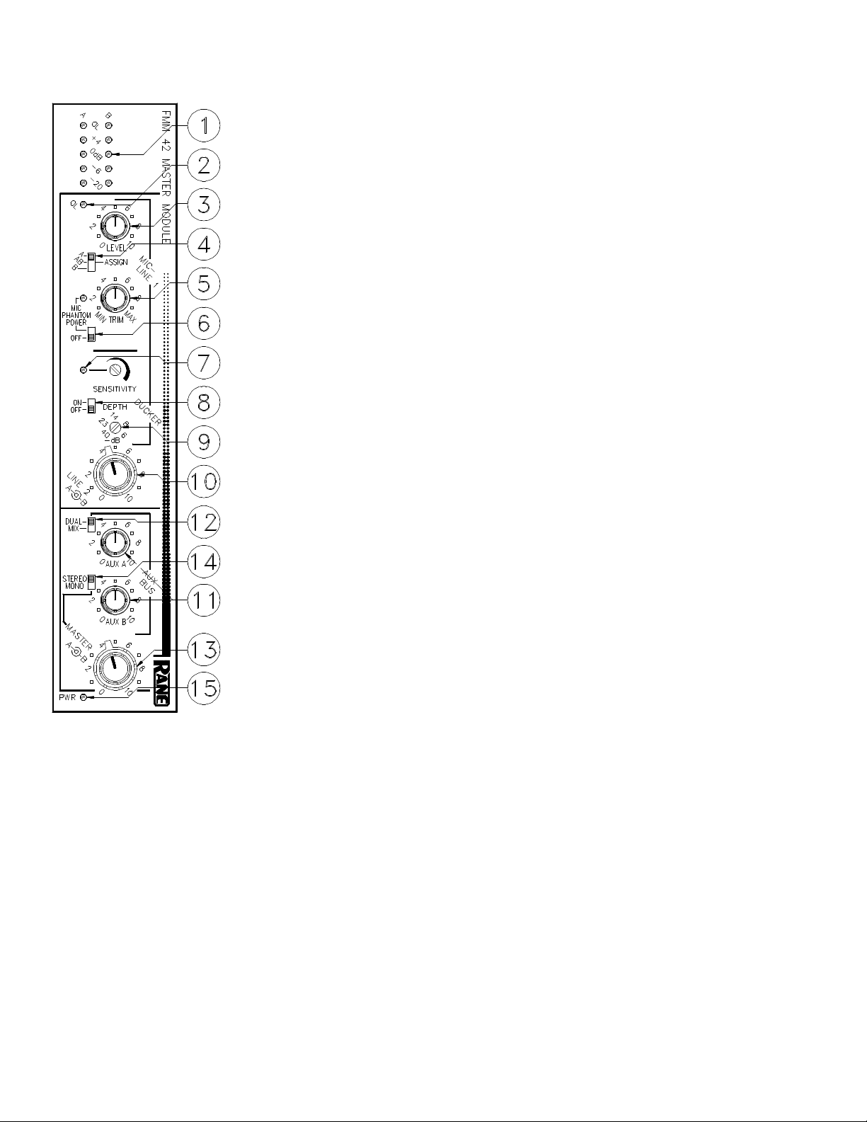
FRONT PANEL DESCRIPTION
1. MASTER OUTPUT METERS. These LEDs illuminate at the levels indicated.
They track ouput level of each channel only.Calibration: “0dB” LED = Peak equivalent
for +4dBu balanced output level.
2. INPUT 1 OVERLOAD INDICATOR. This red LED illuminates when the input
amplifier approaches a level of 4dB below clipping.
3. INPUT 1 LEVEL CONTROL. This rotary control sets the output level of the Mic/
Line 1 input stage. It is used to set the relative balance between this input and all others
including the Bus inputs.
4. ASSIGN SWITCH. This three position slide switch sends the output of the Input 1
stage to Channel A only, both A & B, or Channel B only.
5. INPUT 1 TRIM CONTROL. This knob is used to set the gain of the input ampli-
fier to accomodate a broad range of microphone sensitivities or line levels.
6. PHANTOM POWER SWITCH. When in the ON position, Phantom Power
(15VDC) is applied to pins 2 and 3 of the 3-pin INPUT connector on the rear panel. This
voltage level is adequate to operate all but the most esoteric microphone types.
7. DUCKER SENSITIVITY CONTROL AND INDICATOR. This rotary screw-
driver control sets the level at which a signal applied to Input 1 causes all other inputs to
be attenuated. The adjacent LED illuminates when this action takes place.
8. DUCKER ON/OFF SWITCH. In the OFF position, you may ignore items 7 and 9
on this page.
9. DUCKER DEPTH CHARGE. This rotary screwdriver adjustment sets the amount
of attenuation imposed on all audio in the module by the priority circuitry described in
great detail elsewhere in this document.
10. LINE 2 A & B INPUT CONTROLS. This concentric rotary control adjusts the
input levels of the LINE 2 INPUT.
11. AUX A AND B BUS LEVEL CONTROLS. These rotary level controls set the
amount of signal going out on the AUX BUS OUTS/LOOPS jacks (tips).
12. DUAL / MIX SWITCH. In the Dual (stereo) mode, Aux A is routed to Master A
only, Aux B mixes with Master B only. In the Mix (mono) position, both Aux inputs sum
with both Master A and B outputs.
13. MASTER A AND B OUTPUT LEVEL CONTROLS. These concentric level
controls set the output levels of Master A and B channels. If rotated individually they
serve the function of both output faders and pan controls.
14. STEREO / MONO SELECTOR SWITCH. In the STEREO mode, Master A and
B outputs are totally independent. In the MONO mode, A and B are summed and identical.
15. POWER INDICATOR. Indicates power, as indicated.
Page 3

REAR PANEL DESCRIPTION
1. 3-PIN INPUT CONNECTOR. To be used for either mic or line inputs, pin 2 is hot
“+”, pin 3 is return “–”, and pin 1 is signal ground. Unbalanced inputs should drive pin 2
and use pin 1 as ground.
2. MIC / LINE SELECTOR. In its out position, this switch sets the input stage gain
for microphone usage. When pushed in, the gains are restructured for use with line level
inputs.
3. STEREO LINE 2 INPUT. This is a TRS stereo input. Tip is connected to Channel
A, ring gets connected to Channel B.
4. FLEX BUS INPUT CONNECTOR. When using the FMM 42 with other Flex
mixer modules, the Bus Output of the last module in the system prior to the FMM 42
would be connected to this Input via the 7-pin DIN cable (supplied).
5. FLEX BUS THRU CONNECTOR. To be used in situations where more than one
master module is required. When two or more FMM 42s are required, the second
modules’s Bus Input should be connected to this Output.
NOTE: Special cabling may be constructed which would allow the
bus inputs and outputs to be used for direct inputs and outputs.
See the Flex User’s Guide for additional information.
6. AUX A AND B BUS OUTS/LOOPS CONNECTORS. These ¼" TRS (tip=send,
ring=return) connectors may be used for inserting reverb units or other signal processing
devices (e.g., FPE 13s and FME 15s) in series with the Aux A and B Bus Return Loops.
With Flex units, use a single ¼" TRS cable connecting these inserts to the Patch I/O jacks.
Note: these Loops may be used as additional line inputs when the Flex Bus Inputs are not
used. This requires special ¼" TRS cables with Tip left open, Ring as signal hot and
Sleeve as ground. Additionally, they may serve as AUX outs by using a mono (tip, sleeve)
connector.
7. MASTER A AND B OUTPUTS. These 3-pin balanced outputs use pin 2 as hot,
pin 3 as return and pin 1 as signal ground. For unbalanced operation, pin 2 should be used
as hot and pin 1 as ground. Do not short pin 3 to any other pin. Leave it open.
8. POWER INPUT CONNECTOR. USE ONLY A MODEL RS 1, RAP 10, FRS 8,
OR OTHER REMOTE AC POWER SUPPLY APPROVED BY RANE. The FMM 42 is
supplied with a remote power supply suitable for connection to this input jack. Consult
the factory for replacement or substitution.
9. CHASSIS GROUND POINT. A 6-32 threaded hole used for chassis
grounding purposes. See the CHASSIS GROUNDING note on the last page for
details.
10. GROUND LIFT SWITCH. On this unit, the Ground Lift switch is
located along the bottom edge (vertical mounting), or along the right-hand side
(horizontal mounting). Since the switch’s location may prevent easy use once
installed in the rack, it is suggested you decide which position is required, and
set it before installation. The LIFT position is when the switch is slid to the rear
of the unit.
This switch provides the ability to separate chassis ground and signal ground. Normally, this switch should be in the
LIFT position. In some circumstances it may be necessary to move it to the opposite position to eliminate stubborn hum and
buzz problems. We realize a scientific explanation of this switch would be helpful, unfortunately science doesn’t seem to
have much to do with it. See the CHASSIS GROUNDING note on the last page for details.
If you are tempted to try moving this switch with your power amplifiers turned on or turned up, don't be. Always turn
your amplifier levels down beofre changing your grounds around and then bring them up slowly. Put a speaker re-coner out
of work today!
Page 4

OPERATING INSTRUCTIONS
This unit serves two different, yet similar, functions. It
may be used as a stand-alone mixer/controller or as a master
module for moderate to large mixing systems. Either way it
is a very flexible module.
STAND-ALONE. As an independent mixer, the FMM
42 provides a switchable MIC or LINE balanced INPUT as
well as a stereo LINE-level unbalanced INPUT. This is
useful in situations where an audio source such as music or
noise masking needs to be combined with a microphone for
paging or voice-over requirements. When combined with the
capabilities of the ducker feature, the FMM 42 is quite
powerful, indeed. To use the module in this way, connect
your mic or line source to the MIC/LINE 1 INPUT jack, set
the push button adjacent to the connector for the proper
source and then set the input trim appropriately. This is
accomplished by watching the red overload LED just below
the output meters. The input TRIM control should be set so
that the overload light comes on only when the input signal
is as high as it can ever get. Setting too low a level in the
input gain stage can impair noise performance later in the
system. The level control follows the input gain stage and is
used to set the relative mix between this input and all others.
If you are using a microphone which requires phantom
power, set the MIC PHANTOM POWER switch to its on
position.
If the LINE 2 (STEREO) Input is to be used, the concentric controls just below the Ducker controls are used to set
the relative levels for this input.
If you wish to use the ducker, set its slide switch to the
on position and adjust the SENSITIVITY control so the
Ducker engages at the required Input 1 level. Normally, this
is used as a paging priority controller. In this case you speak
into the microphone at a normal level and adjust the SENSITIVITY so the LED illuminates only when voice is present.
Setting the sensitivity too high might cause nuisance
engagement of this controller. When the ducker activates, all
audio (except Input 1) at the master outputs will be attenuated by the amount set by the depth control. The amount of
gain reduction may be varied between -6dB and -40dB.
MASTER MODULE OPERATION. The FMM 42 was
primarily designed to serve as a master output module for
use with FMI 14 input modules and FPM 44, FPM 42, CM
86 and FLM 82 mixers. These modules have 7-pin DIN bus
outputs which may be connected to the BUS Input of the
FMM 42. When used this way, everything stated above
regarding the use of this module in a stand-alone fashion
remains true. Now, however, signal is being applied to the
Bus Input for both the Master A and B as well as the Aux A
and B programs. All signal applied to the master buses will
be present at the master output and mix with whatever has
been connected to the FMM 42 itself. If the page override
Ducking system is in use, all material arriving at the FMM
42 through the Bus Inputs will be attenuated when the circuit
activates as well as all local program (except for Input 1).
The amount of gain reduction will be the same for all
material.
The Aux A/B Bus Inputs feature looping capabilities
using the tip/send, ring/return convention. This is the normal
insert point for reverb or other signal processing units. In
addition, the Aux A/B Bus Inputs may be assigned. In the
DUAL (stereo) position, each Aux Input mixes independently to its natural Output, i.e., Aux A mixes with Master
A, and Aux B mixes with Master B. In the MIX (mono)
position, the sum of Aux A + Aux B add equally to Master
Outputs A & B. See the Flex Users Guide for more details.
POWER SUPPLY. As noted elsewhere in this manual,
NEVER USE A POWER SUPPLY OTHER THAN THE
ONE SUPPLIED FROM THE FACTORY OR AN EXACT
REPLACEMENT OBTAINED FROM RANE CORPORATION. This unit’s power supply input is designed for an AC
supply, delivering 18-24 volts, from a center-tapped transformer capable of supplying at least the current demanded
by this product. Using any other type of supply may damage
the unit and void the warranty (which at two years parts and
labor is worth safeguarding, don’t you think?).
IMPORTANT NOTE
CHASSIS GROUNDING
Rane Flex modules are supplied with a rear or
bottom/side mounted ground-lift switch. The unit is
shipped with this switch in the “grounded” position,
tying circuit ground to chassis ground. If after hooking
up your system it exhibits excessive hum or buzzing,
there is an incompatibility in the grounding configuration between units somewhere. Your mission, should you
accept it, is to discover how your particular system wants
to be grounded. Here are some things to try:
1. Try combinations of lifting grounds on units that
are supplied with ground lift switches or links.
2. If your equipment is in a rack, verify that all
chassis are tied to a good earth ground, either through
the line cord grounding pin or the rack screws to another
grounded chassis.
3. Units with outboard power supplies do NOT
ground the chassis through the line cord. Make sure that
these units are grounded either to another chassis which
is earth grounded, or directly to the grounding screw on
an AC outlet cover by means of a wire connected to a
screw on the chassis with a star washer to guarantee
proper contact.
Please refer to Rane Note 110 (supplied with your
unit and available on request at no charge if you lose it)
for further information on system grounding.
©Rane Corporation 10802 47th Avenue West, Mukilteo WA 98275-5098 TEL(206) 355-6000 FAX(206) 347-7757
All features & specifications subject to change without notice. 520-232 1293Printed in the U.S.A. on Recycled Paper
 Loading...