

Page 1
OPERATING / SERVICE MANUAL FMI 14
QUICK START
No one likes to read manuals. Most like to plug in and turn on. That’s usually OK, and with
only a very few exceptions, damage is unlikely to result from such procedures with the FMI 14.
First, determine if the input is to be microphone or line and set the MIC/LINE select switch
accordingly. If a microphone is to be used which requires phantom power, set the PHANTOM
POWER switch to its ON position. With the SENDS and MASTER levels all the way down, set
the PAD and GAIN controls so that the highest input will not illuminate the overload light. If
the SENDS are to be used, set the Aux Send selector switches to the desired position. Adjust
the A and B MASTER output levels to deliver the required amount of signal to the bus and
direct outputs.
NEVER CONNECT ANYTHING EXCEPT AN APPROVED RANE POWER SUPPLY
TO THE THING THAT LOOKS LIKE A TELEPHONE JACK ON THE REAR OF THE
FMI 14. This is an AC input and requires special attention if you do not have an operational
power supply EXACTLY like the one that was originally packed with your unit. See the full
explanation of the power supply requirements elsewhere in this manual.
SYSTEM CONNECTION
When connecting the FMI 14 to other components in
your system for the first time, leave the power supply for
last. This will give you a chance to make mistakes and
correct them before any damage is done to your fragile
speakers, ears and nerves.
INPUTS on the FMI 14 are balanced. This means that
standard 3-pin (XLR) connectors on the ends of any good
quality cable will work well with the FMI 14 and microphones of your choosing. As with all Rane products, pin 2 is
used for “hot” or “+” signal polarity, pin 3 is “return” or “-”
and pin 1 is signal ground. If you are using the ¼" TRS line
input, tip is hot, ring is return and sleeve is ground. For
unbalanced inputs, drive pin 2 or tip as hot and pin 1 or
sleeve as ground. It is not necessary to short pin 3 or ring to
ground on Flex series microphone inputs. It will not hurt
anything, either. You may use either pin 1 or case for shield
ground on the 3-pin input. (See Rane Note 110 for further
information on this subject).
OUTPUTS. The FMI 14’s Master outputs are balanced.
The Aux outputs are unbalanced. On the balanced outputs,
tip is hot, ring is return and sleeve is ground. If unbalanced
output is required, use only a tip-ring-sleeve connector and
leave the ring unterminated. A “mono” type ¼" (tip and
sleeve only) connector may be used on the Aux outputs.
They are unbalanced only and require no special attention.
Again, have a look at Rane Note 110 for more detail.
BUS OUTPUTS. The 7-pin DIN Bus input and output
may be used only with other Flex modules. These are not
MIDI inputs and outputs. A
detailed explanation of the wiring
in these connectors is not necessary. The only thing the user must
know is that only a DIN cable as
supplied with each module from
the factory should be used. If, for
some reason, there is not a cable in
the box with your FMI 14, you
should contact Rane for a replacement. If you are in a bind and need
to make one, a 5-pin DIN may be
used instead of a 7-pin. The two
outside pins are not used on the
FMI 14 and have been included
due to possible future compatibility
requirements. All pins should be
wired “straight through” (1 to 1, 2
to 2, etc.).
A typical FLEX system using FMI 14s would be one
where several FMI 14s are used as input channels for a
mixer with one FMM 42 Master module as the termination.
In a case like this, the first FMI 14’s BUS OUT would go to
the second’s BUS IN, its BUS OUT to the third’s BUS IN,
and so on down the line. The last FMI 14’s BUS OUT would
connect to the FMM 42’s BUS IN. This would sum all FMI
14s properly. See the Flex User’s Guide for additional
details.
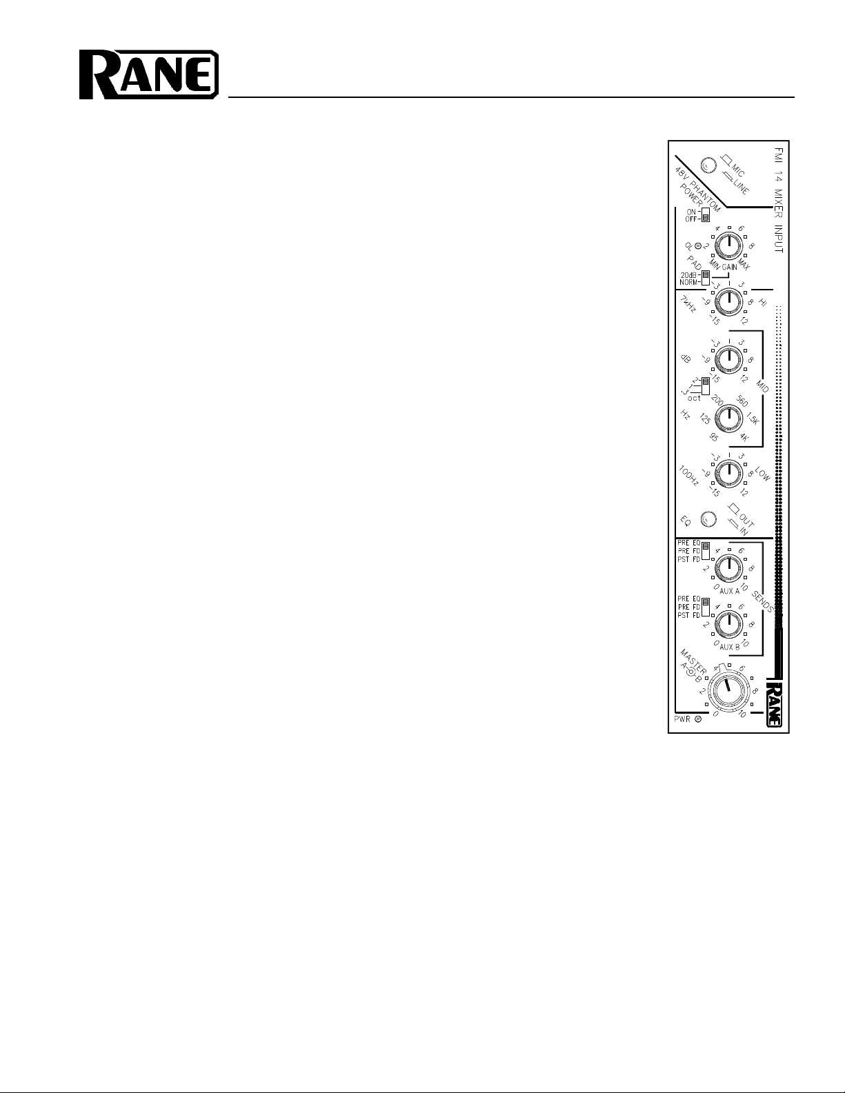
MIXER INPUT
Page 2
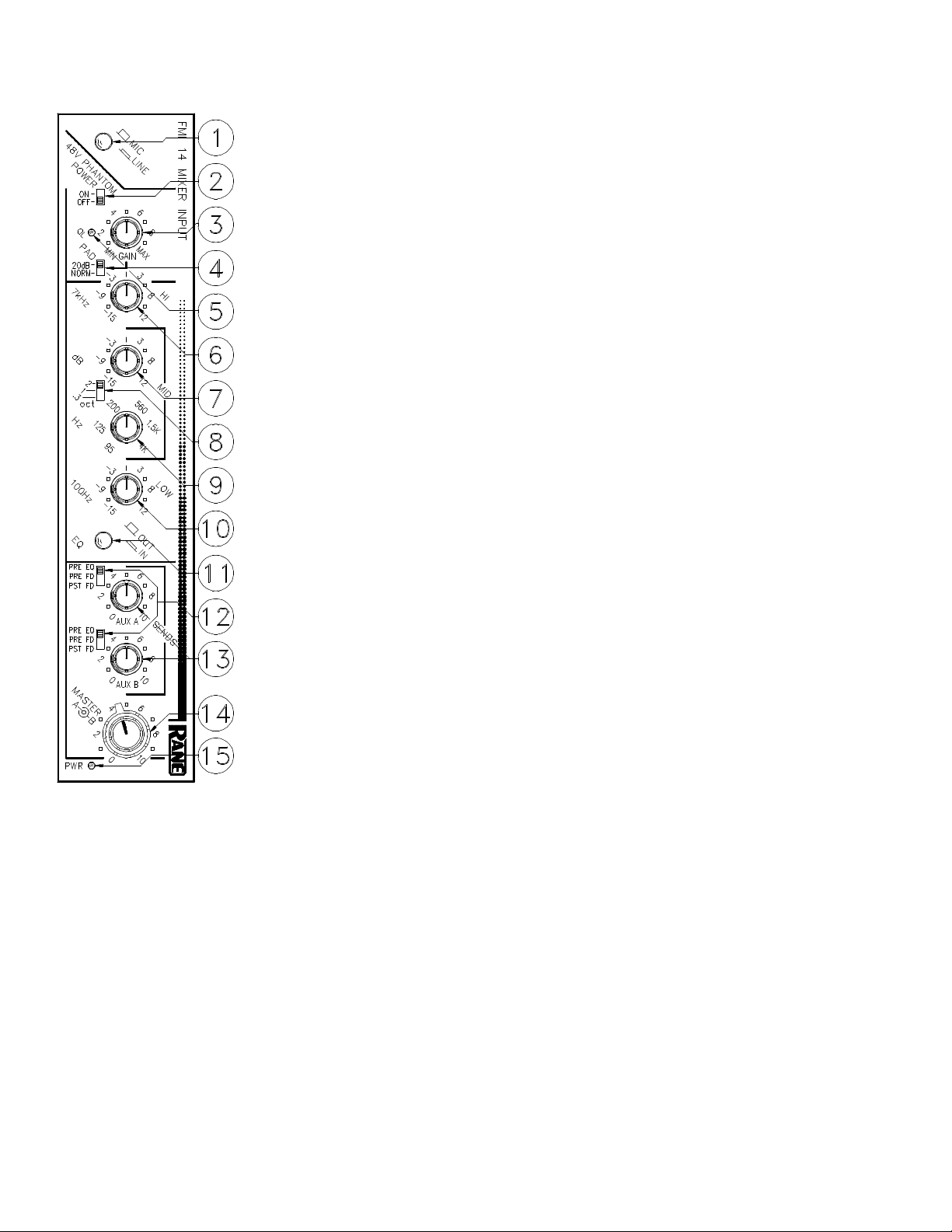
FRONT PANEL DESCRIPTION
1. MIC / LINE SELECT SWITCH. A pushbutton switch which in its out position
determines that the 3-pin MIC INPUT on the rear will be active and structures the input
gain accordingly. In the in position the balanced ¼" LINE INPUT is active and gain is
reduced to suit.
2. 48V PHANTOM POWER SWITCH. In the “on” position, 48 volts D.C. phantom
power is applied to pins 2 and 3 of the 3-pin MIC INPUT connector.
3. INPUT GAIN CONTROL. This rotary control increases input GAIN as it is rotated
clockwise. Its range is from 20dB at full CCW rotation to 60dB at full CW rotation.
4. 20dB PAD SWITCH. In its 20dB postion, this switch decreases the gain range of
the input GAIN control (item #3, above). by 20dB, which is times ten. If it is set to its
NORM position, the calibrations indicated above are true.
5. CHANNEL OVERLOAD INDICATOR. This red LED illuminates any time any
signal level is within 4dB of clipping. Five key locations are monitored.
6. HIGH FREQUENCY EQ CONTROL. This rotary control determines the amount
of boost or cut applied to the FMI 14’s passband by its Accelerated Slope™ high frequency
filter. The center detent, cleverly placed at the center of rotation of this control, provides a
ground for the filter which bypasses it. Rotating this knob clockwise increases the gain of
the of the mixer above 7kHz in a shelving fashion to a maximum of +12dB; CCW from
center decreases the gain to a minimum of -15dB.
7. MIDRANGE EQ CONTROL. As above, clockwise rotation increases gain, how-
ever in this instance we have a bandpass type curve as opposed to a shelving characteristic.
Again, the range is from -15dB to +12dB.
8. MIDRANGE BANDWIDTH SELECTOR. This three-position switch allows the
user to select 1/3, 1 or 2 octave coverage from the midrange filter.
9. MIDRANGE CENTER FREQUENCY CONTROL. A rotary control which
determines the center frequency of the midrange filter. Its range is from 95Hz to 4kHz.
10. LOW FREQUENCY EQ CONTROL. This rotary control determines the amount
of boost or cut applied to the FMI 14’s passband by its Accelerated Slope™ low frequency
filter. The center detent provides a ground for the filter which bypasses it. Rotating this
knob clockwise increases the gain of the mixer below 100Hz to a maximum of +12dB in a shelving fashion; CCW from
center decreases the gain to a minimum of -15dB.
11. EQUALIZER DEFEAT SWITCH. In its out position, all audio is routed around the equalizer section defeating its
action. Only when it is pressed in will any of the equalizer controls be active.
12. AUX SEND SELECTOR SWITCHES. These switches determine the source for the Auxiliary Outputs, A and B. In
the PST FD position, the respective Aux Out is picked up after the Master level controls. In the PRE FD position, the source
is after the EQ, if engaged, but prior to the Master levels. If PRE EQ is used, the signal is obtained before the EQ section.
13. AUX A / B SEND CONTROLS. These rotary controls determine the output level to both the direct ¼" AUX OUT-
PUTS on the rear as well as the Aux sends in the BUS OUT connector.
14. MASTER A / B LEVEL CONTROLS. These concentric rotary controls determine the output level to both the direct
¼" MASTER OUTPUTS on the rear as well as the Master outputs in the BUS OUT connector. Rotated together, they act as
a conventional level control. Rotated individually, they create a pan function.
15. POWER INDICATOR LED. This yellow LED illuminates any time an approved Rane AC remote power supply
such as an RS 1 (included), RAP 10, VC 18 or an FRS 8 is connected to the unit and is active.
Page 3

REAR PANEL DESCRIPTION
1. 3-PIN MIC INPUT CONNECTOR. Pin 2 is positive, pin 3 is negative and pin 1 is
signal ground.
2. ¼" LINE INPUT CONNECTOR. This ¼" TRS connector is used for connecting a
LINE level INPUT to the FMI 14. Tip is (+), ring is (-) and sleeve is ground.
3. ¼" INSERT CONNECTOR. This ¼" TRS connector is to be used to connect
external processing, such as effects and equalizers to the input section of the FMI 14. The
tip is send, the ring is return and the sleeve is ground. Forward-thinking products such as
the Rane FPE 13 and FME 15 equalizers have TRS jacks on them that directly connect to
this patch input with a stereo cable wired tip to tip, ring to ring, and sleeve to sleeve. See
the block diagram on the FMI 14 data sheet for exact location of this insert.
4. FLEX BUS IN. This connector is intended to be used to connect the FLEX BUS
OUT of another Rane Flex unit to the FMI 14. See the system connection section for
details.
5. FLEX BUS OUT. This connector is intended to be used to connect the FMI 14 to
another piece of Rane Flex equipment. Any other use will void the warranty on your firstborn child.
NOTE: Special cabling may be constructed which would allow the
Bus Inputs and Outputs to be used for direct inputs and outputs.
See the Flex User’s Guide for additional information.
6. AUX A / B OUTPUTS. These are unbalanced direct AUX Outputs. These Outputs
contain only local material. This means that any Aux material on the Bus input will not be
present at these Outputs. See the FMI 14 data sheet block diagram for details.
7. MASTER A / B OUTPUTS. These are balanced ¼" outputs. Tip is (+), ring is (-)
and sleeve is ground.
8. GROUND LIFT SWITCH. This switch provides the ability to separate chassis
ground and signal ground. Normally, this switch should be in the LIFT position. In some
circumstances it may be necessary to move it to the opposite position to eliminate stubborn
hum and buzz problems. We realize a scientific explanation of this switch would be
helpful, unfortunately science doesn’t seem to have much to do with it.
If you are tempted to try moving this switch with your power amplifiers turned on or
turned up, don't be. Always turn your amplifier levels down before changing your grounds
around and then bring them up slowly. Put a speaker re-coner out of work today!
9. REMOTE POWER SUPPLY INPUT. The FMI 14 is supplied from the factory with a Model RS 1 Remote Power
Supply suitable for connection to this input jack. The power requirements of the FMI 14 call for an 18-24 volt AC centertapped transformer only. This is not a DC input. It is not a telephone jack.
Never use a power supply with your FMI 14 other than the one supplied or an exact replacement obtained or approved
by Rane Corporation. Using any other type of supply may damage the unit and void the warranty. Two years parts and labor
is worth safeguarding, don’t you think?
10. GROUND CONNECTOR. Since the FMI 14 is powered from a remote AC power supply which does carry chassis
ground through to the grounding pin of the AC cord, this screw has been provided in case your system does not have another
earth grounding means such as through rack rails, etc. Its use or disuse should be determined by your specific application.
Page 4

OPERATING INSTRUCTIONS
The FMI 14 has been designed to operate in a very
similar fashion to most mixer input strips. The input GAIN
control, PAD, Overload indicator and PHANTOM POWER
selector have all been placed at the top (in the vertical
mounting configuration). Next down the line comes the EQ
section, then the AUX source selectors and level controls,
and finally the MASTER faders. Anyone familiar with
mixers should have no difficulty mastering the FMI 14.
INPUT SECTION. When setting up the input section,
one should always take as much gain as possible right at the
input. Therefore, the highest level audio from the MIC or
LINE INPUT should just about light the Overload light. It is
good idea to experiment with different gain settings to make
sure the input stage is properly set. Failure to do so will
sacrifice noise performance down the line.
EQUALIZER. The EQ section of the FMI 14 is particularly interesting. The high frequency and low frequency
shelving tone controls feature Rane’s patented Accelerated
Slope™ circuitry. This helps eliminate the unwanted
influence over out-of-band signals so prevalent in standard
shelving controls. What this means is that the rolloff rates
are much steeper than those usually encountered.
The midrange section of the FMI 14s equalizer is
parametric. The bandwidth may be set to one of three
settings: 1/3 octave, 1 octave, or 2 octaves. The center
frequency may be adjusted over a range of 95Hz to 4kHz.
All three bands cover an amplitude range of -15dB to
+12dB. All of the level controls feature a grounded center
detent thus ensuring that a “zero” setting gives you just what
you wanted: a guaranteed zero (flat).
The EQ IN/OUT switch provides a “hard-wire” bypass
around the equalizer section. Even though the center detents
of the EQ level controls provide a guaranteed zero, some
engineers use the bypass to compare the EQ setting with the
dry non-EQ without changing settings.
AUX SENDS. The AUX Outputs of the FMI 14 feature
both direct outputs on the rear as well as AUX BUS Outputs
to be combined with other Aux Outputs from other FMI 14s
or Flex mixer units. The source of the AUX Outputs are
switch selectable. They may be driven directly from the
input stage in the PRE EQ position, from the output of the
equalizer in the PRE FD position or from the outputs of the
MASTER A and B faders in the PST FD position.
MASTER OUTPUTS. The MASTER Outputs also
feature direct, balanced outputs on the rear of the FMI 14 as
well as BUS Outputs for combination with other Flex Bused
modules. The Bus Outputs are normally eventually terminated with a Rane FMM 42 Master Module which can mix
Masters and Auxes into a final stereo output. In this combination a complete audio mixer may be assembled. When
Busing two FMI 14s or other Flex mixer modules together
without an FMM 42, the ¼" MASTER OUTPUTS of the last
module in the “chain” contain the sum of all previous Master
levels. The ¼" AUX OUTPUTS do not contain the sum.
BUS INS AND OUTS. The FLEX BUS standard dictates
the use of 7-pin connectors. This may seem strange since the
FMI 14 only uses 5 of them, 2 for Aux, 2 for Master and 1
for ground. There are other possible Flex modules which
may use the other two pins in the future. Should this occur,
the FMI 14 and all other modules not using the 2 spares will
be compatible. The BUS IN and OUT connectors pass the 2
unused connections straight through from Input to Output
thus ensuring their compatibility.
IMPORTANT NOTE
CHASSIS GROUNDING
Rane commercial equalizers are supplied with a rear
mounted ground-lift switch. The unit is shipped with this
switch in the “grounded” position, tying circuit ground
to chassis ground. If after hooking up your system it
exhibits excessive hum or buzzing, there is an incompatibility in the grounding configuration between units
somewhere. Your mission, should you accept it, is to
discover how your particular system wants to be
grounded. Here are some things to try:
1. Try combinations of lifting grounds on units that
are supplied with ground lift switches or links.
2. If your equipment is in a rack, verify that all
chassis are tied to a good earth ground, either through
the line cord grounding pin or the rack screws to another
grounded chassis.
3. Units with outboard power supplies do NOT
ground the chassis through the line cord. Make sure that
these units are grounded either to another chassis which
is earth grounded, or directly to the grounding screw on
an AC outlet cover by means of a wire connected to a
screw on the chassis with a star washer to guarantee
proper contact.
Please refer to Rane Note 110 (supplied with your
unit and available on request at no charge if you lose it)
for further information on system grounding.
©Rane Corporation 10802 47th Avenue West, Mukilteo WA 98275-5098 TEL(206) 355-6000 FAX(206) 347-7757
All features & specifications subject to change without notice. 520-214 1193Printed in the U.S.A. on Recycled Paper
 Loading...