

Page 1
Professional Audio Products Data Sheet
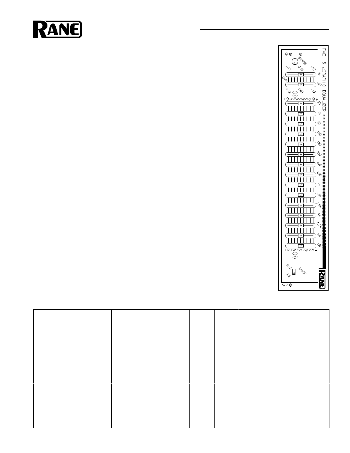
FME 15 microGraphic Equalizer
General Description
The Rane Model FME 15 microGraphic
Equalizer is a single channel, 2/3 octave graphic
equalizer. Representing a third-generation
evolution of Rane’s pioneering constant-Q
approach to equalization—now the standard of
the industry—the FME 15 features the very best.
The very best sound, performance and reliability.
Technically, the FME 15 is an interpolating
constant-Q design. This means the bandwidth of
each individual filter is guaranteed to be narrow
enough to prevent unwarranted interaction
between filters, yet wide enough to produce
exactly the type of correction curve demanded
by even the most unusual acoustic surroundings.
Interpolating means the FME 15 produces
ripple-free combining of adjacent response
curves. And constant-Q produces constant
bandwidth curves for all slider positions. This
differs dramatically from conventional designs
which are encumbered with the unfortunate
characteristic of changing bandwidth with
changing boost/cut amounts.
The FME 15 features a RANGE switch for
allowing high slider resolution in the ±6dB
mode. The ±12dB mode provides a wide range
of control over system audio. Front panel
controls include separate GAIN controls for
input and output levels as well as an Overload
indicator monitoring all critical nodes. Separate
Input and Output GAIN controls allow maximizing of headroom at all times.
A passive BYPASS switch with indicator
allows for easy A-B comparison of results or
signal restoration in the event of power loss or
unit failure. And the rear of the unit provides
balanced 3-pin, ¼" TRS and #6 terminal strip
connectors, as well as a convenient ¼" TRS
Patch Input/Output. This patch input allows
connection to a standard insert loop jack with a
single stereo patch cord.
FME 15
microGRAPHIC EQUALIZER
Features
• 15-BAND EQUALIZER CHANNEL
• INTERPOLATING DESIGN
• INPUT & OUTPUT LEVEL CONTROLS
• PASSIVE BYPASS SWITCH & LED
• EQ RANGE SWITCH
• 2/3-OCTAVE CONSTANT-Q BANDWIDTH
Parameter Specification Limit Units Conditions/Comments
Equalizer: Channels One
..........Bands (15) 2/3 Octave ISO Spacing From 25Hz to 16kHz
..........Type Interpolating Constant-Q Smooth Combining
..........Accuracy 3 % Center Frequency
..........Travel 20 mm Positive Grounded Center Detent
..........Range ±12 or ±6 1 dB Switch Selectable
Overall Input Gain Range -12 to +12 1 dB
Overall Output Gain Range +12 to -12 1 dB
Passive Bypass Switch Yes LED Indicated
Low Filter 15Hz, 18dB/Oct, Butterworth 3% Hz Internally Defeatable
Signal-to-Noise Ratio re +20dBu/+4dBu 20kHz Noise Bandwidth, Balanced
108/92 2 dB Sliders Centered, Gains Full Up
91/75 2 dB Full Boost, Gains Full Up
106/90 2 dB Full Cut, Gains Full Up
Maximum Current 300 mA RMS Current From Remote Supply
• OVERLOAD INDICATOR
• LOW AND RFI FILTERS
• U.S. PATENT 4,891,841
• ¼" TRS INSERT PATCH JACK
• 3-PIN, TERMINAL STRIP & ¼" TRS
INPUT/OUTPUT CONNECTORS
Page 2

FME 15
microGRAPHIC EQUALIZER
Rear Panel Block Diagram
Professional Audio Products Data Sheet
Application Information
The FME 15 microGraphic Equalizer offers
the same high quality interpolating constant-Q
performance as its long throw relative, the GE
30. No compromises or trade-offs exist in
selecting an FME 15 microGraphic. All circuitry,
components and specifications meet or exceed
the GE 30. Only the slider throw is different, plus
you gain a RANGE switch to help extend the
usable travel if modest boost/cut amounts are
needed. This model exists for people requiring
the very best equalizer possible in the smallest
space allowable.
Interpolating constant-Q graphic equalizers
arose from the sound professional’s need for
greater control with less interaction than previously possible with conventional equalizers. The
FME 15’s advanced filter design yields smooth
bandpass response when two sliders are used in
tandem, enabling the user to “interpolate”
between ISO centers to reach problem areas
precisely. Truth in slider position also became a
requirement. The curve traced out by the slider
positions on interpolating constant-Q designs
indeed represents the actual changes to the
frequency response. On conventional designs
they do not.
You use an interpolating constant-Q graphic
the same way you use a conventional graphic.
You just get the desired results quicker, with far
less after adjustment to the adjacent sliders,
eliminating a phenomenon Rane calls “equalizing
the equalizer”.
© Rane Corporation 10802 47th Ave. W., Mukilteo, WA 98275-5098 TEL(206) 355-6000 FAX(206) 347-7757
Printed in the U.S.A. on Recycled Paper All features & specifications subject to change without notice 520-125 JAN95
 Loading...