

Page 1
OPERATING / SERVICE MANUAL FLM 82
QUICK START
This section has been provided as a convenience for those without enough patience to read
the entire manual. If you are experienced with this unit or other Rane Flex modules, these few
words should help you refresh your memory.
The FLM 82 is a line level mixer only. It will not accept microphone input levels. Inputs are
accepted in unbalanced pairs. Each of the four two-channel Inputs are set up in a tip-ring-sleeve
configuration such that the tip is Channel A and the ring is Channel B. Input or mix levels are
controlled by a concentric LEVEL control on each Input channel. The outer knob determines the
mix level for Channel B, the inner is Channel A. The AUX SEND Level controls are set up the
same way; outer knob determines the send level for Channel B, inner is Channel A.
The Aux Sends may be internally switched so that they are pre or post input fader. FLM 82s
are shipped from the factory with the internal switches set to the pre position. To change this,
the top cover must be removed and the switches reset to the desired position following the
legends on the circuit board assembly.
Like many of the Flex Series modules, the FLM 82 provides busing capabilities so that it may
be included in a larger mixer configuration with other modules. The FLEX BUS INPUT on the
rear will sum all previous modules on the Bus with the Inputs of the FLM 82. The FLEX BUS
OUT connector makes available all signals on the Bus Input as well as locally generated program material in the FLM 82. The STEREO/MONO switch on the rear adds Channel A and
Channel B signals together for a mono feed to the MASTER OUTPUTS A and B on the rear of
the unit. Engaging this switch also causes the AUX A and B signals to be combined to one. The
AUX LOOP A and B jacks on the rear may be used either as direct Aux Outputs or for inserting
processing in series with the Aux buses before the are added to the direct A and B Master
Outputs. The use of these jacks will have no effect on Aux signals placed on the FLEX BUS.
The MASTER A and B level controls set the output level to the MASTER A and B Outputs on
the module, and have no effect over levels being delivered to the FLEX BUS OUT connector.
Never connect anything except an approved Rane power supply to the red thing that looks
like a telephone jack on the rear of the FLM 82. This is an AC input and requires special
attention if you do not have a power supply exactly like the one that was originally packed with
your unit. See the explanation of the power supply requirements elsewhere in this manual.
MIXER INPUT
SYSTEM CONNECTION
When connecting the FLM 82 to other components in
your system for the first time, leave the power supply for last .
This lets you make mistakes and correct them without damage
to your fragile speakers, ears and nerves.
INPUTS. All inputs on the FLM 82 are unbalanced. Each
of the four TRS INPUT jacks is arranged so that tip drives
Channel A and ring drives Channel B. Use shielded cable for
all input and output wiring. Connect the shield to the sleeve of
the input connector. Rane Note 110 specifies that shields
should be connected at the receiving end of signal cables
only. A copy of this tech note was included with your FLM
82; if you need another, let us know.
BUS INS AND OUTS When connecting the FLM 82 to
other Flex modules through the Bus connectors, it is best to
use the DIN connecting cables supplied with the unit or
replacements ordered from the factory. If this is inconvenient,
any good quality DIN cable may be used as long as it is wired
straight through , that is pin 1 to pin 1 etc. It must be a
shielded cable for optimum performance. You may notice that
the DIN connectors on the FLM 82 and other Flex Modules is
of the seven-pin variety. The FLM 82 does not use the outer
two pins and will therfore not suffer terribly if a five-pin DIN
connector is used. The extra two
pins have been reserved in the Flex
Bus Standard for future use and are
there just in case.
OUTPUTS. Although labeled as loops, the AUX LOOP A
and AUX LOOP B connectors may be used as outputs. If one
wishes to use the loops as outputs and break the signal path so
that the Aux signals do not reach the Master A and B Outputs,
use a mono ¼" tip-sleeve plug, use the tip as hot and the
sleeve as signal ground. If you do not wish to break the signal
path between the Aux Bus and the Master Output, short the
tip and ring of a TRS plug together and use this junction as
your Aux Output.
The other application for this set of jacks is for inserting
processing of your choice between the Aux A and B Buses of
the mixer and the direct Master A and B Outputs. If this is
your choice, use the tip as send and the ring as return.
Connecting devices to these jacks has no effect over what the
FLM sends the Aux Buses on the FLEX BUS OUT connector.
The MASTER A and B outputs are fully balanced. Use the
tip of each connector as hot, ring is not hot and the sleeve
is signal ground.
Page 2

FRONT PANEL DESCRIPTION
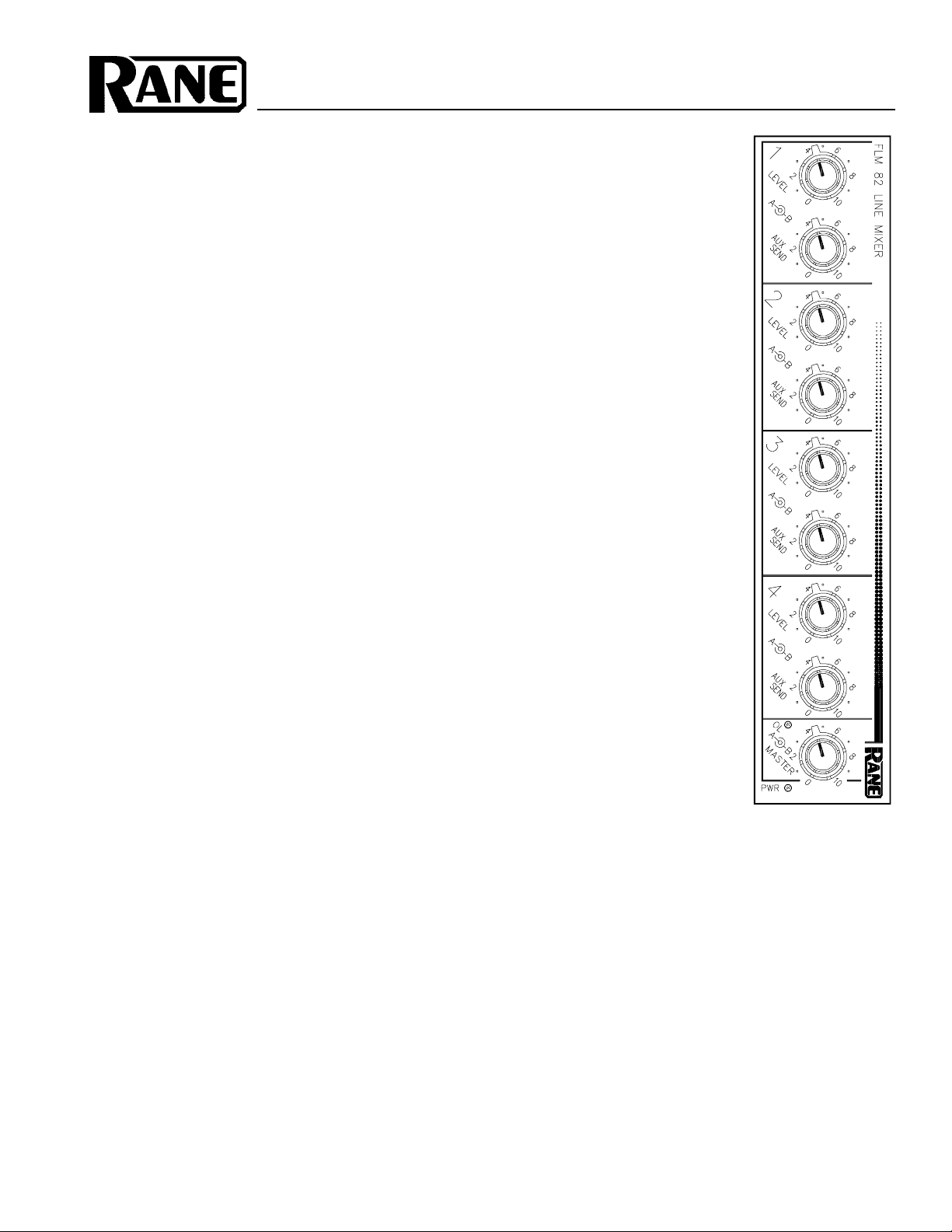
1. INPUT LEVEL CONTROLS. Each of the four input channels has one pair
2. AUX SEND LEVEL CONTROLS. These concentric level pots adjust the
3. MASTER A AND B LEVEL CONTROLS. Another set of concentric
4. POWER INDICATOR. This is a yellow light emitting diode. The light,
of concentric LEVEL controls. These controls allow the user to set the
amount of level from each pair of input channels (A and B) to be delivered
to the respective mix buses. The inner knob controls Channel A, the outer
Channel B. These set the input mix for both the FLEX BUS OUTs and the
MASTER A and B Outputs on the rear of the unit.
Aux mix on both the FLEX BUS OUT as well as the levels to the AUX
LOOP A and B jacks on the rear panel. The inner knob adjust Channel A,
the outer Channel B. As mentioned elsewhere in this manual, the AUX
SENDS may be either PRE or POST fade (before or after the input LEVEL
controls). This determination is made internally based on the switch positions located on the printed circuit board beneath the top cover.
controls, the inner knob adjusts the MASTER OUTPUT A level on the rear
panel, the outer sets the MASTER OUTPUT B level. These controls have no
effect on the FLEX BUS OUT levels.
when present, is created by the forward bias condition of the gallium
arsenide junction encapsulated within the yellow plastic, which serves two
purposes: one, to act as a lens for the light and the other to protect the
delicate solid state chip within. Or, if you prefer, if this light is lit the
powers on.
Page 3

1. LINE INPUTS. These are the four main stereo inputs to the FLM 82. The
tip of each connects to the respective Channel A input, the ring is used for
Channel B.
2. FLEX BUS OUT. This DIN connector supplies all local master A and B
program signal as well as the Aux A and B signals. It also sends any
information coming into the FLEX BUS IN connector on to other modules
further down the line.
3. FLEX BUS IN. This connector is used to tie other Flex Series mixing
modules to the FLM 82. Both master & aux program material from the FLM
82 is added to this BUS INPUT.
4. STEREO / MONO SWITCH. Engaging this switch causes the A and B
MASTER buses (local only, not the Flex Bus) and the Aux A and B buses to
be added together to create one signal from two. It may be used in instances
where only mono inputs are connected to the FLM 82 and two outputs (A
and B) are required on both MASTER and AUX Outputs. It may be also
used to convert a two channel program input to a mono output. This switch
affects only the direct outputs on the rear of the unit. It has no effect over
FLEX BUS INPUTS or FLEX BUS OUTPUTS.
5. AUX LOOPs A and B. Primarily designed to allow signal processing to be
inserted in the Aux buses, these jacks may also be used for direct Aux
Outputs should the need arise. See the System Connection section on the
front page of this manual for more information.
REAR PANEL DESCRIPTION
6. MASTER OUTPUTs A and B. These are TRS balanced jacks. The tip is
the pos connection, the ring is neg and sleeve is signal ground.
7. POWER INPUT CONNECTOR. USE ONLY A MODEL RS 1, FRS 8,
OR OTHER REMOTE AC POWER SUPPLY APPROVED BY RANE. The
FLM 82 is supplied with a remote power supply suitable for connection to
this input jack. Consult the factory for replacement or substitution.
8. GROUND LIFT SWITCH. This switch provides the ability to separate
chassis ground and signal ground. Normally, this switch should be in the
LIFT position. In some circumstances it may be necessary to move it to the
opposite position to eliminate stubborn hum and buzz problems. We realize
a scientific explanation of this switch would be helpful, unfortunately
science doesnt seem to have much to do with it. See the CHASSIS
GROUNDING note on the last page for details. If you are tempted to try
moving this switch with your power amplifiers turned on or turned up,
DONT BE. ALWAYS TURN YOUR AMPLIFIER LEVELS DOWN
BEFORE CHANGING YOUR GROUNDS AROUND and then bring them
up slowly.
9. CHASSIS GROUND POINT. A 6-32 screw is used for chassis grounding purposes. See the CHASSIS GROUNDING note on the last page for
details.
Page 4

OPERATING INSTRUCTIONS
Having read this manual in its proper order, you should be
convinced that the FLM 82 is a four stereo input line mixer.
The section on the front cover titled SYSTEM CONNECTION has given you the ammunition needed to properly
connect the inputs and outputs as well as the FLEX BUS
interconnections. Now for some knob twisting.
The level of a stereo source connected to the #1 INPUT
jack on the rear panel is controlled by the Channel 1 concentric LEVEL controls on the front. The inner knob is for
Channel A, the outer for Channel B. This is the only level
control available for controlling signals going to the FLEX
BUS OUT connector. For identical levels on Channel A and
Channel B, the knobs should be kept at the same position
relative to each other. If a different level needs to be set for
each input, the controls may be rotated separately. The
Channel 1 AUX SEND level controls operate the same way
and control the same source. AUX SEND A and B levels are
delivered to the Aux A and B Buses and forwarded to the
FLEX BUS OUT connector as well as to the tips of the A and
B AUX LOOPs on the rear panel. All four Input channels and
front panel LEVEL controls operate in the same fashion.
The MASTER OUTPUT A and B jacks on the rear have
another level control possibility. The concentric MASTER A
and B knobs set the final output level for these jacks.
When engaged, the STEREO/MONO switch on the rear
panel sums the MASTER OUTPUT A and B signals together.
This switch does the same thing to the AUX A and B signals.
It should be noted that the action of this switch does not apply
to the FLEX BUS outputs. They will remain independent in
either mode.
The AUX LOOPs are used to insert processing or effects
between the AUX SENDs and the MASTER OUTPUTs. Two
possible options will accomplish this feat. If you wish to
insert a Flex series equalizer such as an FPE 13 or an FME
15, all you need is a shielded stereo cable. Use this cable
between the AUX LOOP connector(s) on the FLM 82 and the
PATCH I/O jack on the equalizer. This one connection
accommodates inputs and outputs from both units. If you are
using a piece of gear built by someone rude enough to omit
this convenience, a cable with a stereo plug on one end and
two mono plugs on the other is required. The tip of the AUX
LOOP jack is send or output and the ring is return or
input. Connect the tip of the TRS plug to the tip of the plug
to be used as the input to the processor. Connect the ring of
the TRS plug to the tip of the processors output plug. All
sleeves should be tied together through the cable shields. This
slightly unusual cable is a standard product for most cable
companies. The SYSTEM CONNECTION section on the
front page of this document explains how to use the AUX
LOOPs as Aux Outputs.
The Aux signals may be picked up before or after the
Input level controls. The switches which determine the pickup points are located beneath the top cover of the unit and
require some disassembly to reach them. All FLM 82s are
shipped from the factory in the pre fade position. To
change, remove the screws securing the top and rear cover
(one piece) and carefully remove the metalwork. You will see
that the switches have directions printed on the PCB assembly, directing your further actions.
MULTIPLE MODULES. As you have already learned,
the FLM 82 may be used in conjunction with other Flex
mixer modules to create a large system by utilizing the FLEX
BUS IN and OUT jacks on the rear of the unit. Each mixer
module in the system will place its Master and Aux mixes on
the respective buses internally and provide this information to
its FLEX BUS OUTPUT. When these signals are connected
to the FLEX BUS INPUT on a succeeding unit, they will be
combined in the next unit with any local program material
and the sum of the two will be available at the second units
FLEX BUS OUT jack. When daisy chaining several Flex
mixer modules together, the Master Outputs of the last
module in the chain will contain the sum of all modules
before it. The Aux Output on this last module is not a sum,
though proper mixing and summing of Masters and Auxes
can be accomplished with a FMM 42 Master Module
IMPORTANT NOTE
CHASSIS GROUNDING
Rane Flex units are supplied with a rear or side
mounted ground-lift switch. The unit is shipped with this
switch in the grounded position, tying circuit ground to
chassis ground. If after hooking up your system it exhibits
excessive hum or buzzing, there is an incompatibility in
the grounding configuration between units somewhere.
Your mission, should you accept it, is to discover how
your particular system wants to be grounded. Here are
some things to try:
1. Try combinations of lifting grounds on units that
are supplied with ground lift switches or links.
2. If your equipment is in a rack, verify that all chassis
are tied to a good earth ground, either through the line
cord grounding pin or the rack screws to another
grounded chassis.
3. Units with outboard power supplies do NOT ground
the chassis through the line cord. Make sure that these
units are grounded either to another chassis which is earth
grounded, or directly to the grounding screw on an AC
outlet cover by means of a wire connected to a screw on
the chassis with a star washer to guarantee proper contact.
Please refer to Rane Note 110 (supplied with your unit
and available on request at no charge if you lose it) for
further information on system grounding.
©Rane Corporation 10802 47th Avenue West, Mukilteo WA 98275-5098 TEL(206) 355-6000 FAX(206) 347-7757
All features & specifications subject to change without notice. 520-113 MAY95Printed in the U.S.A. on Recycled Paper
 Loading...