

Page 1

OPERATING / SERVICE MANUAL FDA 28
QUICK START
This section is provided as a convenience for those in a rush. If you are experienced with this
unit or other Rane Flex modules, these few words should help refresh your memory.
Inputs may be microphone or line level. The choice between the two is made by setting the
pushbuttons on the rear of the unit near each Input. Follow the silkscreening for proper wiring
hookup. Choose between chassis, signal ground or open for shield connection.
Signal for the Outputs is sourced either before or after the A and B MASTER level controls.
The switches which determine this are located within the confines of the unit’s covers. All FDA
28s are shipped from the factory with the internal switches in the POST fader position.
Once Inputs and Outputs are satisfactorily connected, set the Input GAINs as high as possible
without causing the A and B OverLoad indicators to illuminate steadily for high input levels. If 1
x 8 Mono operation is required, use only one Input and set all STEREO/MONO switches to the
MONO position. If 1 x 4 STEREO operation is chosen, all switches should be in the opposite
position. Mix settings as each application demands.
NEVER CONNECT ANYTHING EXCEPT AN APPROVED RANE POWER SUPPLY
TO THE RED THING THAT LOOKS LIKE A TELEPHONE JACK ON THE REAR OF
THE FDA 28. This is an AC input and requires special attention if you do not have a power
supply EXACTLY like the one that was originally packed with your unit. See the full explanation of the power supply requirements elsewhere in this manual.
DISTRIBUTION
AMPLIFIER
SYSTEM CONNECTION
When connecting the FDA 28 to other components in your system for the first time, leave the
power supply for last. This gives you a chance to make mistakes and correct them without damage
to your fragile speakers, ears and nerves.
INPUTS. The two Inputs on the FDA 28 are balanced. They may also be used in an unbalanced
configuration. Use only shielded cable for Inputs. This wire should always be two-conductor plus
shield, even for unbalanced operation. Balanced Inputs should be connected to both the “+” and “–
” terminals. Tie the shield to either chassis ground for normal use, or to signal ground when using
Phantom Power (required). A neutral ground is not necessary (except when using Phantom Power).
For unbalanced use, connect the hot side of the input cable to “+” and ground to signal ground. If
the input is coming from another piece of equipment in the signal path, connect the shield only at
the receiving end to help prevent ground induced hum. If a microphone is being connected to the
unit, the shield may be connected to the case of the mic as well as to the ground terminal on the
unit.
OUTPUTS. The FDA 28s Outputs are balanced. The same wiring conventions as the Inputs
apply, with one exception. Unbalanced Outputs require tying the “–” Output to Signal Ground.
Page 2
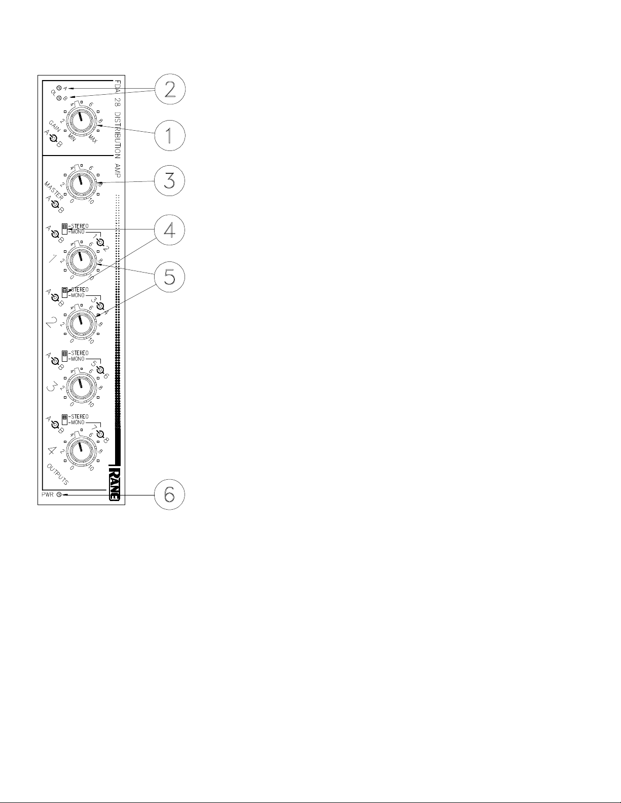
FRONT PANEL DESCRIPTION
The FDA 28 is a combined Stereo or Mono unit. Outputs are labelled in white,
1A/B - 4A/B for STEREO use, and in gray, 1-8 for MONO operation. Note that in
MONO the odd Output Channels are connected to INPUT A and the even Output
Channels to INPUT B.
1. INPUT GAIN CONTROLS. These concentric controls set the Gain of each Input
to be routed to the A and B bus for Stereo operation, or to the odd and even buses
for Mono use. The inner knob controls the level to be sent to bus A (odd), the outer
knob controls the signal applied to bus B (even). Rotating the knobs upward
together from the MIN position creates a “pan centered” effect. Leaving one off and
increasing the other emulates a full pan to one bus or the other.
2. A AND B OVERLOAD INDICATORS. These red LEDs illuminate whenever the
combination of Input level and Input GAIN adjustment cause the input amplifiers to
reach or exceed a level equal to 4dB below clipping.
3. MASTER A AND B LEVEL CONTROLS. These concentric controls set the level
to each of the post buses. Output levels may be selected via the four pairs of
controls connected to the Output sections if the internal PRE/POST switches are in
the POST position (as shipped).
In the PRE position, the MASTER Level control is bypassed for that respective
Output and only the Input GAIN Control and the OUTPUT Level Control have any
effect on an individual Output.
4. STEREO/MONO SWITCHES. To make one or both Inputs drive all eight
Outputs, slide all switches to their MONO positions. In STEREO mode, INPUT A
drives bus A (or odd) only; INPUT B connects to bus B (or even) only. Program
each pair of Outputs as necessary. Monoing one Output pair will have no effect on
the other Outputs.
5. OUTPUT LEVEL CONTROLS. Each pair of OUTPUT controls sets the indi-
vidual Channel Output levels. The inner knob is for Channel A (or odd), the outer is
Channel B (or even).
6. POWER INDICATOR. When this yellow LED is illuminated, the foregoing
information should be correct. If darkness is present at this location, most or all of
the above will be inoperative.
Page 3
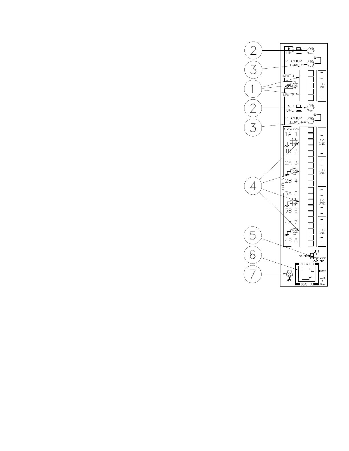
REAR PANEL DESCRIPTION
The FDA 28 uses Euroblocks that disconnect and accommodate any wire size
from 26AWG to 12AWG.
1. INPUT TERMINALS. Use these for either Microphone or Line level INPUTs to be
distributed by the FDA 28. Connect balanced sources to the respective “+”and “–”
terminals, and choose a shield grounding terminal (either signal ground (SIG GND)
or chassis ground). Unbalanced Inputs should connect to “+” and SIG GND only.
When using an unbalanced Input you may leave “–” open, or short it to GND.
2. MIC / LINE SELECTOR SWITCH. In the out position, the respective Input stage
is set for Microphone Input levels. In the depressed position, Line level signals are
accepted.
3. PHANTOM POWER SWITCH. In the on position, 15VDC PHANTOM POWER
appears present on each INPUT, and the LED lights.
4. OUTPUT TERMINALS. Balanced OUTPUT for each Channel. Connect two
conductor shielded cable to “+”and “–” terminals. Tie the shield to chassis, signal
ground, or leave open—your choice. For unbalanced use, you must tie the “–” to
SIG GND. Failure to do so results in improper operation.
5. GROUND LIFT SWITCH. This switch provides the ability to separate chassis
ground and signal ground. Normally, this switch should be in the LIFT position. In
some circumstances it may be necessary to move it to the opposite position to
eliminate stubborn hum and buzz problems. See the CHASSIS GROUNDING note
on the last page for details.
If you are tempted to try moving this switch with your power amplifiers turned on or
turned up, don't be. Always turn your amplifier levels down before changing your
grounds around and then bring them up slowly.
6. POWER INPUT CONNECTOR. USE ONLY A MODEL RS 1, FRS 8, RAP 10,
VC 18 OR OTHER REMOTE AC POWER SUPPLY APPROVED BY RANE. The
FDA 28 is supplied with a remote power supply suitable for connection to this input
jack. Consult the factory for replacement or substitution.
7. CHASSIS GROUND POINT. A 6-32 screw is used for chassis grounding purposes.
See the CHASSIS GROUNDING note on the last page for details.
INTERNAL ASSIGN SWITCHES SHIPPED IN “POST” POSITIONS.
Page 4

OPERATING INSTRUCTIONS
This module serves two similar yet different functions. In
‘all STEREO’ mode, it will split two Inputs into four pairs of
Outputs. The two Inputs may be set at different levels if
necessary via the concentric MASTER level controls. All
eight Outputs (4 pairs) may be set as necessary through the
use of the four sets of concentric OUTPUT level controls. In
‘all MONO’ mode, one Input may drive all eight Outputs,
again with separate MASTER and OUTPUT level controls.
Any combination of STEREO and MONO Outputs may be
used.
The internal PRE/POST switches allow you to determine
whether an individual Output is to be routed through the
MASTER level control. If all eight switches are set to the
PRE position, the MASTER level control is defeated and has
no effect over any of the Outputs. It is for this reason that all
FDA 28s are shipped from the factory with all switches in the
POST position. This helps eliminate questions about possible
defective controls. One normal use of the FDA 28 is in a
situation where the MASTER level controls adjust the level of
all Outputs together without disturbing the relative levels
between the Outputs. There are eight separate switches so that
some zones or splits can be adjusted with the MASTERs and
some not.
For optimum noise performance from microphone Inputs,
it is always advisable to run as much gain as possible in the
first stage of amplification. For this reason, set the GAIN
control so that at the highest expected sound levels at the
microphone the overload LEDs occasionally blink. Obviously, trading constantly lit overload LEDs (and the ensuing
distortion) for lower noise is not a great idea. Make sure the
selector switch on the rear is in the out position for MIC use.
In the LINE level configuration, unity gain is probably a good
place to start. This may be found at approximately “4” on the
GAIN control.
POWER SUPPLY. As noted elsewhere in this manual,
never use a power supply with your FDA 28 other than the
one supplied from the factory or an exact replacement
obtained or approved from Rane Corporation. This unit’s
power supply input is designed for an AC supply, delivering
18-24 volts from a center-tapped transformer capable of
supplying at least the current demanded by this product.
Using any other type of supply may damage the module and
void the warranty (which at two years parts and labor is worth
safeguarding, don’t you think?).
IMPORTANT NOTE
CHASSIS GROUNDING
Rane commercial equalizers are supplied with a rear
mounted ground-lift switch. The unit is shipped with this
switch in the “grounded” position, tying circuit ground to
chassis ground. If after hooking up your system it exhibits
excessive hum or buzzing, there is an incompatibility in
the grounding configuration between units somewhere.
Your mission, should you accept it, is to discover how
your particular system wants to be grounded. Here are
some things to try:
1. Try combinations of lifting grounds on units that
are supplied with ground lift switches or links.
2. If your equipment is in a rack, verify that all chassis
are tied to a good earth ground, either through the line
cord grounding pin or the rack screws to another
grounded chassis.
3. Units with outboard power supplies do NOT ground
the chassis through the line cord. Make sure that these
units are grounded either to another chassis which is earth
grounded, or directly to the grounding screw on an AC
outlet cover by means of a wire connected to a screw on
the chassis with a star washer to guarantee proper contact.
Please refer to Rane Note 110 (supplied with your unit
and available on request at no charge if you lose it) for
further information on system grounding.
©Rane Corporation 10802 47th Avenue West, Mukilteo WA 98275-5098 TEL(206) 355-6000 FAX(206) 347-7757
All features & specifications subject to change without notice. 520-354 NOV94Printed in the U.S.A. on Recycled Paper
 Loading...