

Page 1
OPERATING / SERVICE MANUAL
QUICK START
You’re in a hurry, so you better read this quick, so you can get started right away.
The input may be mic or line level. Choose by pressing the pushbutton located near the
MASTER control. A balanced input uses “+” as hot, “–” as return and GND as shield ground. An
unbalanced input should connect to “+” and GND. Leave “–” unconnected.
The outputs are “+” and “–”. Normally GND is not used on the sending end. Ground the
shield only at the receiving end.
Signal for the outputs is sourced either before or after the MASTER level control. The switches
which determine this are located within the confines of the unit’s covers. All FDA 18s are
shipped from the factory with the switches in the POST position.
Once the input and outputs are satisfactorily connected, set the input gain as high as possible
without causing the overload (OL) indicator to illuminate steadily with very high input levels.
NEVER CONNECT ANYTHING EXCEPT AN APPROVED RANE POWER SUPPLY TO
THE RED THING THAT LOOKS LIKE A TELEPHONE JACK ON THE REAR OF THE FDA
18. This is an AC input and requires special attention if you do not have a power supply EXACTLY like the one that was originally packed with your unit. See the full explanation of the
power supply requirements elsewhere in this manual.
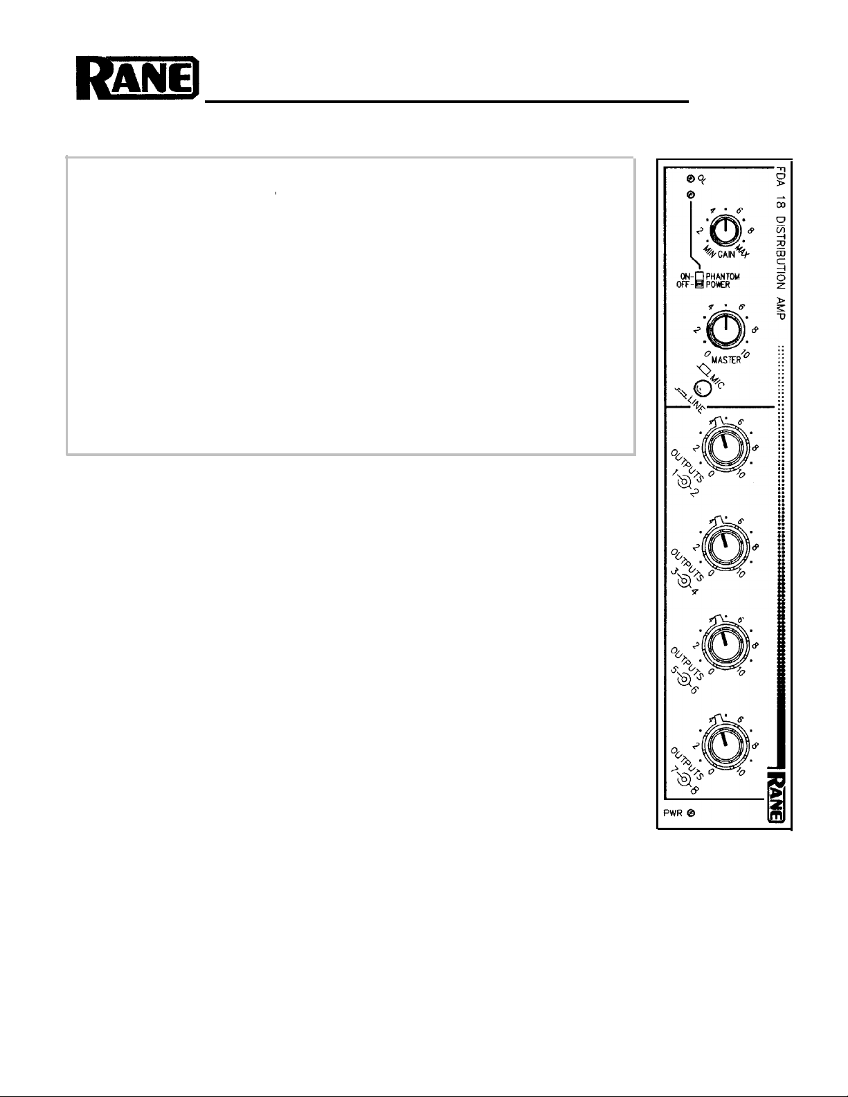
FDA 18
SYSTEM CONNECTION
When connecting the FDA 18 to other components in your system for the first time, LEAVE
THE POWER SUPPLY FOR LAST. This gives you a chance to make mistakes and correct them
without damage to your fragile speakers, ears and nerves.
INPUTS. The input on the FDA 18 is fully differentially balanced, i.e., it is a true instrumentation amplifier. It may also be used in an unbalanced configuration. Use only shielded cable for
your input. This wire should always be two-conductor plus shield, even for unbalanced operation.
Balanced inputs should be connected to the “+” pin and “–” pin for signal hot and return. The
shield should be tied to GND. A neutral “pin 1” ground is not necessary (except when using phantom power). For unbalanced use, connect the hot side of the input cable to “+” and the signal return to GND. It is never necessary on any Rane Flex module to ground the pin 3 input in the
unbalanced mode; however, it won’t hurt anything either. If the input is coming from another
piece of equipment (as opposed to a mic), connect the shield only at the receiving end to help prevent ground induced hum. If a microphone is the source, connect the shield to the case of the mic
as well as pin 1, and to the ground terminal on the unit. This is mandatory when using phantom
power.
OUTPUTS. The FDA 18’s outputs are fully balanced using a cross-coupled type of output line
driver stage. Use two conductor shielded cable for interconnecting to the next piece of equipment. Normally, grounding the shield only at the receiving unit gives the best shielding, and the
most hum-free performance.
The cross-coupled output stage is capable of driving lines as long as 1000 without problems.
Longer lines (in excess of a mile) can be driven by directly paralleling two outputs.
Page 2
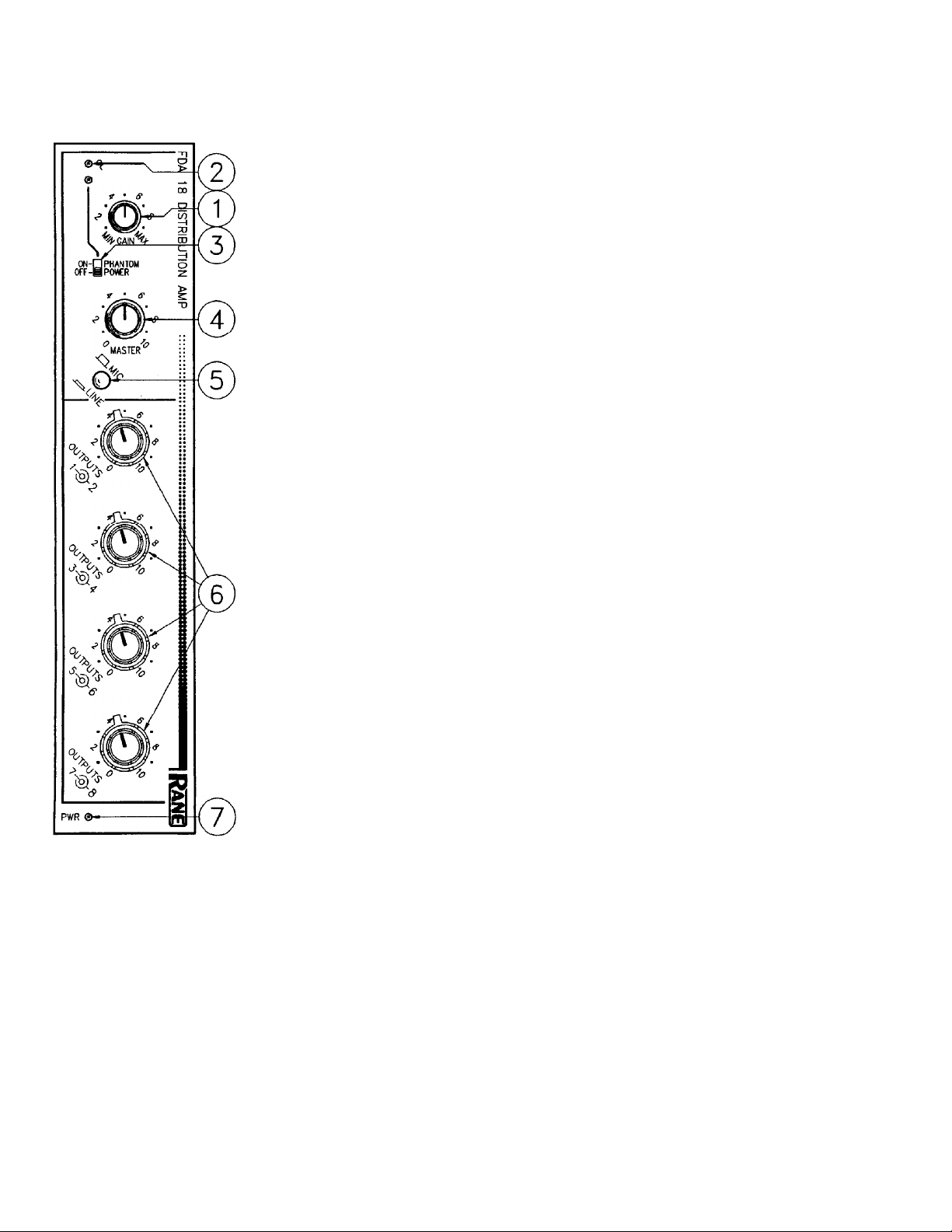
FRONT PANEL DESCRIPTION
1. INPUT GAIN CONTROL. This control sets the gain of the input. The adjustment
MIN to MAX range is from 26 dB to 70 dB when MIC is selected, and from -7 dB to 37 dB
for LINE sources. Set the highest level that does not cause the OL indicator to come on
continuously.
2. OVERLOAD INDICATOR. This red LED illuminates whenever the combination of
input level and input gain adjustment causes the input amplifier to reach or exceed a level
equal to 4 dB below clipping.
3. PHANTOM POWER SWITCH AND INDICATOR. In the ON position (LED on),
15 VDC phantom power appears on each input terminal on the rear of the module.
4. MASTER LEVEL CONTROL. This control sets the signal level appearing on the inter-
nal distribution bus. Output levels may be selected via the four pairs of concentric controls
connected to the output sections. This is true, however, only if the internal PRE/POST
switches are in the POST position (as shipped).
In the PRE position, the MASTER level control is bypassed for that respective output
and only the input GAIN control and the individual OUTPUT level control has any affect.
5. MIC/LINE SWITCH. In the out position, the input is scaled for microphone input lev-
els. In the depressed position, the input stage is set for line-level input.
6. OUTPUT LEVEL CONTROLS. These concentric controls set each individual output
level. The inner knobs are for odd numbered channels, and the outer knobs are for even
numbered channels.
7. POWER INDICATOR. When this little yellow LED illuminates, the foregoing informa-
tion applies. If darkness persists at this location — ignore the above. Pity.
Page 3

REAR PANEL DESCRIPTION
1. INPUT TERMINALS. Use these for either a microphone or a line level input to be dis-
tributed by the FDA 18. Connect a balanced source to the respective “+”, “–” and GND
pins (pins 2, 3 and 1 respectively). An unbalanced input should connect to “+” and GND
only. When using an unbalanced input, you may leave “–” open, or short it to GND, doesn’t
matter.
2. OUTPUT
shielded cable to “+” and “–”.
For unbalanced use, you must ground the “–”
proper operation.
3. GROUND LIFT SWITCH. This switch (mounted on the side) provides the ability to sepa-
rate chassis ground and signal ground. Normally, this switch should be in the LIFT position
(pull toward the rear). In some circumstances it may be necessary to move it to the opposite
position to eliminate stubborn hum and buzz problems.
We realize a scientific explanation of this switch would be helpful, unfortunately science
doesn’t seem to have much to do with it. See the CHASSIS GROUNDING note on the last
page for details.
If you are tempted to try moving this switch with your power amplifiers turned on or turned
up, DON’T BE. ALWAYS TURN YOUR AMPLIFIER LEVELS DOWN BEFORE
CHANGING YOUR GROUNDS AROUND and then bring them up slowly.
4. POWER INPUT CONNECTOR. USE ONLY A MODEL RS 1, FRS 8, RAP 10, OR
OTHER REMOTE AC POWER SUPPLY APPROVED BY RANE. The FDA 18 is supplied
with a remote power supply suitable for connection to this input jack. Consult the factory for
replacement or substitution.
TERMINALS. Balanced output for each channel. Connect two-conductor
Normally the shield is tied only at the next unit’s input.
output, Failure to do so results in im-
5. CHASSIS GROUND POINT. A 6-32 threaded hole used for chassis grounding purposes.
See the CHASSIS GROUNDING note on the last page for details.
NOTE: ASSIGN SWITCHES SHIPPED IN “POST” POSITIONS
Page 4

OPERATING INSTRUCTIONS
This module serves the very straightforward function of
splitting, or distributing, one balanced input signal into 8
separate balanced outputs. Each output has its own level
control.
The internal PRE/POST switches allow you to determine
whether an individual output is to be routed through the
MASTER level control. If all eight switches are set to their
PRE positions, the input MASTER control is completely
bypassed and has no effect over any of the outputs. This is
why FDA 18s ship from the factory with all switches in the
POST position. This helps reduce questions about possible
defective controls. A common use of the FDA 18 is a situa-
tion where the MASTER level control adjusts the level of
all outputs together without disturbing the relative levels
between them. There are eight separate switches, so you
may program some zones or splits to be adjusted with the
MASTER control, and others not.
For optimum noise performance from microphone inputs, it is always advisable to run as much gain as possible
in the first stage of amplification. For this reason, set the
gain control so that at the highest expected sound levels at
the microphone the overload LEDs occasionally blink. Obviously, trading constantly lit overload LEDs (and the ensuing distortion) for lower noise is not a great idea. Make
sure the MIC/LINE selector switch is in the OUT position
for microphone use. In the LINE level configuration, unity
gain is probably a good place to start. This may be found at
approximately “4” on the GAIN control.
POWER SUPPLY. As noted elsewhere in this manual,
NEVER USE A POWER SUPPLY WITH YOUR FDA 18
OTHER THAN THE ONE
TORY OR AN EXACT REPLACEMENT
FROM RANE CORPORATION.
This unit’s power supply input is designed for an AC sup-
ply, delivering 18-24 volts, from a center-tapped trans-
former capable of supplying at least the current demanded
by this product. Using any other type of supply may dam-
age the module and void the warranty (which at two years
parts and labor is worth safeguarding, don’t you think?).
FROM THE FAC-
OBTAINED
IMPORTANT NOTE
CHASSIS GROUNDING
Rane Flex Series modules are supplied with either a
rear, or a bottom/side mounted ground-lift switch. The
unit is shipped with this switch in the “grounded” position, tying circuit ground to chassis ground. If after
hooking up your system it exhibits excessive hum or
buzzing, there is an incompatibility in the grounding
configuration between units somewhere. Your mission,
should you accept it, is to discover how your particular
system wants to be grounded. Here are some things to
try:
1. Try combinations of lifting grounds on units that are
supplied with ground lift switches or links.
2. If your equipment is in a rack, verify that all chassis
are tied to a good earth ground, either through the line
cord grounding pin or the rack screws to another
grounded chassis.
3. Units with outboard power supplies do not ground
the chassis through the line cord. Make sure that these
units are grounded either to another chassis which is
earth grounded, or directly to the grounding screw on
an AC outlet cover by means of a wire connected to a
screw on the chassis with a star washer to guarantee
proper contact.
Please refer to Rane Note 110 (supplied with your
unit and available on request at no charge if you lost
your first one) for further information on system
grounding.
Copyright 1990, Rane Corporation 10802 47th Ave. W. Mukilteo, WA 98275 (425)355-6000
All features & specifications subject to change without notice 520-172 1090
Page 5

RISK OF ELECTRIC SHOCK
DO NOT OPEN
CAUTION
IMPORTANT SAFETY INSTRUCTIONS
1. Read these instructions.
2. Keep these instructions.
3. Heed all warnings.
4. Follow all instructions.
5. Do not use this apparatus near water.
6. Clean only with a dry cloth.
7. Do not block any ventilation openings. Install in accordance with manufacturer’s instructions.
8. Do not install near any heat sources such as radiators, registers, stoves, or other apparatus (including ampliers) that produce heat.
9. Do not defeat the safety purpose of the polarized or grounding-type plug. A polarized plug has two blades with one wider than the other. A grounding-type plug has two blades and a third grounding prong. e wide blade or third prong is provided for your safety. If the provided plug does not
t into your outlet, consult an electrician for replacement of the obsolete outlet.
10. Protect the power cord and plug from being walked on or pinched particularly at plugs, convenience receptacles, and the point where it exits from
the apparatus.
11. Only use attachments and accessories specied by Rane.
12. Use only with the cart, stand, tripod, bracket, or table specied by the manufacturer, or sold with the apparatus. When a cart is used, use caution
when moving the cart/apparatus combination to avoid injury from tip-over.
13. Unplug this apparatus during lightning storms or when unused for long periods of time.
14. Refer all servicing to qualied service personnel. Servicing is required when the apparatus has been damaged in any way, such as power supply
cord or plug is damaged, liquid has been spilled or objects have fallen into the apparatus, the apparatus has been exposed to rain or moisture, does
not operate normally, or has been dropped.
15. e plug on the power cord is the AC mains disconnect device and must remain readily operable. To completely disconnect this apparatus from
the AC mains, disconnect the power supply cord plug from the AC receptacle.
16. is apparatus shall be connected to a mains socket outlet with a protective earthing connection.
17. When permanently connected, an all-pole mains switch with a contact separation of at least 3 mm in each pole shall be incorporated in the electrical installation of the building.
18. If rackmounting, provide adequate ventilation. Equipment may be located above or below this apparatus, but some equipment (like large power
ampliers) may cause an unacceptable amount of hum or may generate too much heat and degrade the performance of this apparatus.
19. is apparatus may be installed in an industry standard equipment rack. Use screws through all mounting holes to provide the best support.
WARNING: To reduce the risk of re or electric shock, do not expose this apparatus to rain or moisture. Apparatus shall not be exposed to dripping
or splashing and no objects lled with liquids, such as vases, shall be placed on the apparatus.
NOTE: is equipment has been tested and found to comply with the limits for a Class B digital device, pursuant to part 15 of the FCC Rules. ese
limits are designed to provide reasonable protection against harmful interference in a residential installation. is equipment generates, uses and can
radiate radio frequency energy and, if not installed and used in accordance with the instructions, may cause harmful interference to radio communications. However, there is no guarantee that interference will not occur in a particular installation. If this equipment does cause harmful interference to
radio or television reception, which can be determined by turning the equipment o and on, the user is encouraged to try to correct the interference
by one or more of the following measures:
• Reorient or relocate the receiving antenna.
• Increase the separation between the equipment and receiver.
• Connect the equipment into an outlet on a circuit dierent from that to which the receiver is connected.
• Consult the dealer or an experienced radio/TV technician for help.
CAU TION: Changes or modications not expressly approved by Rane Corporation could void the user's authority to operate the equipment.
is Class B digital apparatus complies with Canadian ICES-003.
Cet appareil numérique de la classe B est conforme à la norme NMB-003 du Canada.
WARNING
To reduce the risk of electrical shock, do not open the unit. No user
serviceable parts inside. Refer servicing to qualied service personnel.
e symbols shown below are internationally accepted symbols that warn
of potential hazards with electrical products.
is symbol indicates that a dangerous voltage
constituting a risk of electric shock is present within
this unit.
is symbol indicates that there are important
operating and maintenance instructions in the
literature accompanying this unit.
 Loading...