

Page 1
OPERATING / SERVICE MANUAL FAC 28
QUICK START
No one likes to read manuals. Everyone likes to plug in and turn on. That’s usually OK,
and with only a very few exceptions, damage is unlikely to result from such procedures when
initiating the use of a FAC 28.
It is a good idea to begin with all LEVEL controls set to their full counterclockwise
position. Unless you are certain that there is an electrical inversion in one of your amplifiers or
drivers, set both POS INV switches to their POS positions. Both MUTE switches should be
out. If you are using a constant-directivity horn, set the HORN EQ IN/OUT switch to the IN
position and adjust the frequency control per the recommendations of the horn’s manufacturer. Set the PHASE IN/OUT switch to the OUT position. Set the crossover FREQ selector
to the frequency recommended by the speaker manufacturer. Power up the system and set the
input and output levels for appropriate performance.
NEVER CONNECT ANYTHING EXCEPT AN APPROVED RANE POWER
SUPPLY TO THE THING THAT LOOKS LIKE A TELEPHONE JACK ON THE
REAR OF THE FAC 28. This is an AC input and requires special attention if you do not
have an operational power supply EXACTLY like the one that was originally packed with
your unit. See the full explanation of the power supply requirements elsewhere in this manual.
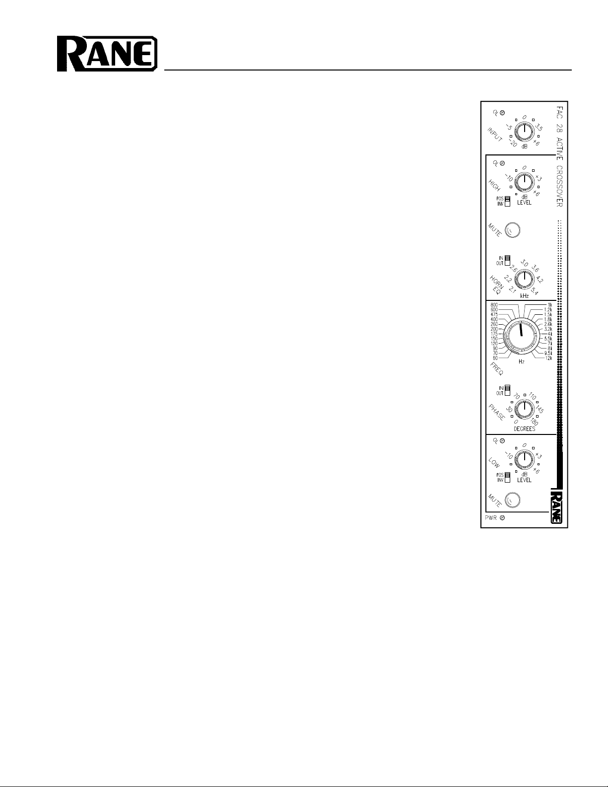
ACTIVE CROSSOVER
SYSTEM CONNECTION
When connecting the FAC 28 to other components in your
system for the first time, leave the power supply for last. This
will give you a chance to make mistakes and correct them
before any damage is done to your fragile speakers, ears and
nerves.
INPUTS on the FAC 28 are balanced. The 3-pin (XLR)
uses pin 2 as “hot” or “+” signal polarity, pin 3 is “return” or
“–” and pin 1 is signal ground. If unbalanced operation is
required, drive pin 2 as hot and pin 1 as ground. The ¼" Input
is a tip-ring-sleeve connector. Tip is “+”, ring is “–”, and
sleeve is ground. Unbalanced ¼" inputs should drive tip as
hot and sleeve as ground and may be either a “mono” ¼" or
TRS ¼" with the ring left open or tied to sleeve, your choice.
See Rane Note 110 for further information on this subject.
OUTPUTS. The FAC 28’s Outputs are balanced as well.
As with the 3-pin Input, pin 2 is hot and pin 3 is not. Pin 1 is
signal ground. True balanced operation requires only the use
of pins 2 and 3 for signal and either case ground (chassis) or
pin 1 signal ground for shielding. If unbalanced output is your
preference, use pin 2 as signal and pin 1 as return. Use case
ground for shield. The ¼" Output is a tip-ring-sleeve character whose polarities match the Input connector. Again, have a
look at Rane Note 110 for more detail.
THE LOW SUM INPUT is used to combine the Low
frequency Outputs of two crossover modules (mono sub bass
in stereo applications). To take advantage of this feature, the
LOW OUT of one crossover module connects to this unbalanced Input. The sum of both modules low frequency
selections then appears at the LOW OUT of the module
whose LOW SUM INPUT is being driven.
3-WAY, 4-WAY etc. Two or
more FAC crossovers may be used
together to produce 3, 4 and 5-way
systems. To accomplish this, the
first unit is driven with full range
audio. The sub bass output is taken
from the LOW OUT of the first
module, the HIGH OUT of the first
module then drives the main INPUT
of the second. For 3-way applications, mid and high are taken from
the LOW and HIGH OUTS of the
second module, respectively. If a
four way system is being constructed, the HIGH OUT of the second module drives the
third, the LOW OUT of the second module becomes the
low-mid, the LOW OUT of the third module is the 3rd
frequency range, the HIGH OUT of the third module becomes
the 4th. See the diagram on the back page of this document as
well as the Flex User’s Guide for more details.
CHOICES need to be made regarding which Input and
Output connectors to use. Generally, the ¼" ins and outs work
well enough and are definitely cheaper to use in terms of
labor and material required to terminate cables with ¼" plugs.
The 3-pins do, however, provide a locking mechanism for
situations where physical abuse can be a problem. The 3-pin
also provides a tighter connection and can be more impervious to corrosion and stresses of time and environment.
Page 2
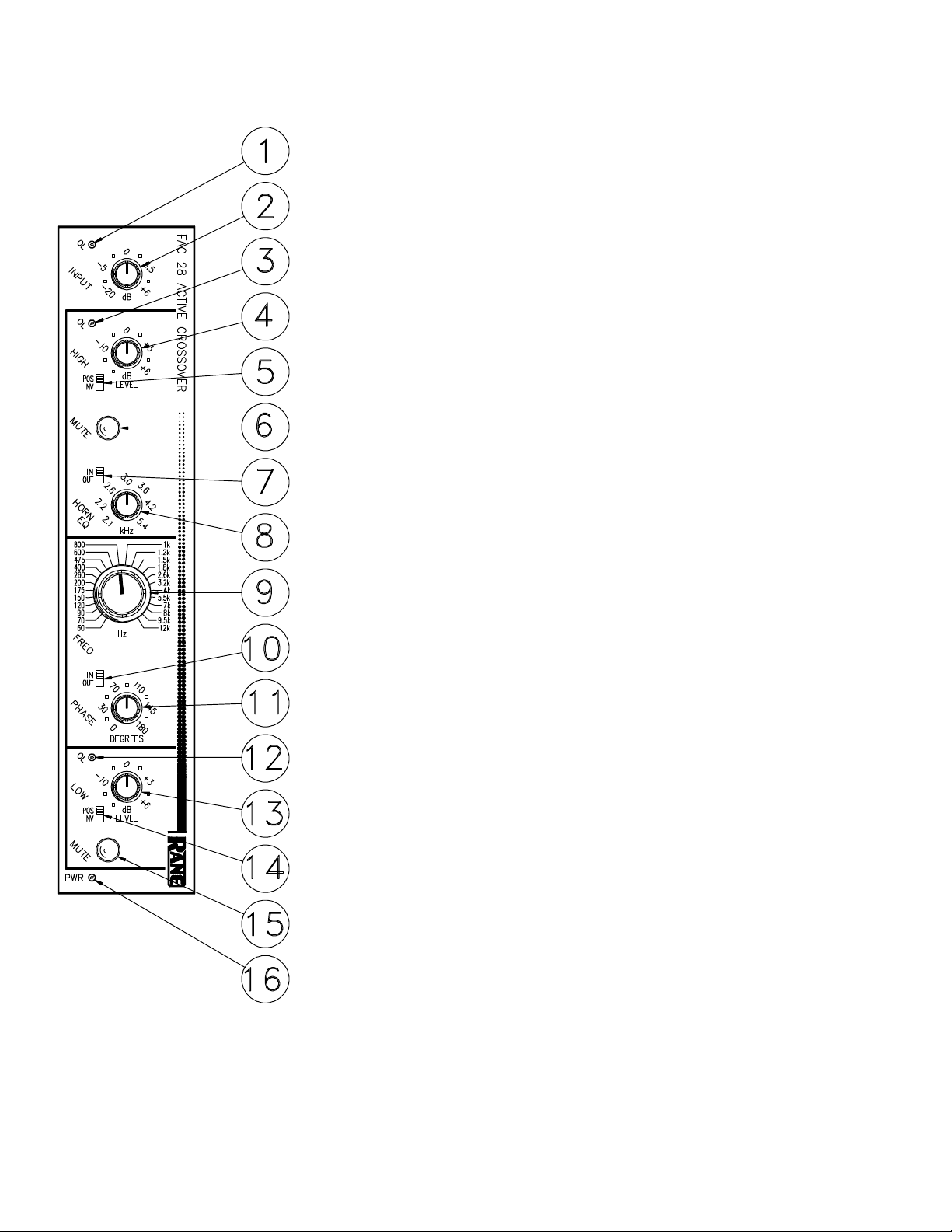
FRONT PANEL DESCRIPTION
1. INPUT OVERLOAD INDICATOR. This red LED will illuminate any time the
input stage is driven to within 4dB of clipping. This level is a function of both
input signal level and the position of the input gain control.
2. INPUT LEVEL CONTROL This rotary control determines the input gain of
the crossover. Its range is from -20dB to +6dB. The majority of applications
should find this control set at 0dB for unity gain.
3. HIGH OUTPUT OVERLOAD INDICATOR. This red LED will illuminate
anytime the high frequency output of the crossover is driven to within 4dB of
clipping. This level is a function of both the INPUT level and the HIGH frequency output LEVEL control.
4. HIGH OUTPUT LEVEL CONTROL. This rotary control determines the
amount of gain to follow the high frequency output of the crossover’s frequency
dividing network. Its range covers OFF to +6dB.
5. HIGH FREQUENCY INVERT SWITCH. This two position slide switch
electrically inverts the high output in the INV position. This may be necessary
where drivers or amplifiers are wired incorrectly or when the crossover’s phase
control lacks sufficient range (more that 180 degrees becomes necessary).
6. HIGH FREQUENCY MUTE SWITCH. In its in position, all output signal
from the High Output of the crossover will be totally muted. This is to be used
when initially setting Levels of the Low Output and during the Phase alignment
process.
7. HORN EQ DEFEAT SWITCH. If a constant-directivity horn is to used on the
High Output, set this switch to the IN position.
8. HORN EQ FREQUENCY CONTROL. This rotary control allows a continu-
ously variable adjustment of the frequency at which boost begins to occur. This
should be set based on the horn manufacturer’s recommendation.
9. CROSSOVER FREQUENCY SELECTOR. This rotary control offers 24
precise frequencies at which the crossover makes the divide between the High
and Low Outputs. It is a binary encoding switch which sets up the digital control
of the filter’s frequency dividing circuits for very high precision.
10. PHASE CONTROL BYPASS SWITCH. In its OUT position, the phase
control has no effect on the low frequency output.
11. PHASE ANGLE CONTROL. This rotary control provides a constantly
variable 0 to 180 degree phase shift between the Low and High Outputs.
12. LOW FREQUENCY OVERLOAD INDICATOR This red LED illuminates
any time the Low Output comes within 4dB of clipping. This level is a function
of INPUT level as well as LOW frequency Output LEVEL.
13. LOW FREQUENCY LEVEL CONTROL. This rotary control varies the
output gain of the LOW frequency section from OFF to +6dB.
14. LOW FREQUENCY INVERT SWITCH. This switch electrically inverts the
polarity of the low output in the INV position. This may be necessary for many
of the same reasons cited in #5, above.
15. LOW FREQUENCY MUTE SWITCH. Identical to #6 above, with the
exception that it Mutes the Low Output.
16. POWER INDICATOR Illuminates whenever the correct AC power is applied
to the unit from a remote power supply.
Page 3

REAR PANEL DESCRIPTION
1. ¼" INPUT CONNECTOR. A balanced/unbalanced Input, the tip is positive, ring
is negative and sleeve is ground. For unbalanced operation, drive the tip as hot and
the sleeve as ground. The ring may be left open or shorted to sleeve. You may also
use a TRS or “mono” connector.
2. 3-PIN INPUT CONNECTOR. Pin 2 is positive, pin 3 is negative and pin 1 is
signal ground. For unbalanced operation, drive pin 2 as hot and 1 as ground.
3. ¼" HIGH FREQUENCY OUTPUT CONNECTOR. This ¼" TRS connector
parallels the 3-pin connector featured in item #4. Tip is positive, Ring is negative
and Sleeve is signal ground.
4. 3-PIN HIGH FREQUENCY OUTPUT CONNECTOR. Pin 2 is positive, pin 3
is negative and pin 1 is signal ground. For unbalanced operation, do not short any
pins to any others. Active balanced outputs operated in the unbalanced mode
should only consist of pin 2 driving the line and pin 1 acting as the return. Pin 3
should be left disconnected.
5. 1/4" LOW FREQUENCY OUTPUT CONNECTOR. This ¼" TRS connector
parallels the 3-pin connector featured in item #6. Tip is positive, Ring is negative
and Sleeve is signal ground.
6. 3-PIN LOW FREQUENCY OUTPUT CONNECTOR. Identical to item #4
above except this one sings the low parts.
7. LOW SUM INPUT CONNECTOR. This is an unbalanced Input consisting of
only a tip and sleeve contact. The tip is positive and the sleeve is ground. It is to
be used to connect the Low frequency Output of another crossover module so that
the Low Out of the driven unit consists of a mono sum of both Low frequency
sections. This is useful for mono sub woofer applications in a two channel (dare
we use the word stereo) system.
8. GROUND LIFT SWITCH. This switch provides the ability to separate chassis
ground and signal ground. Normally, this switch should be in the LIFT position. In
some circumstances it may be necessary to move it to the opposite position to
eliminate stubborn hum and buzz problems. We realize a scientific explanation of
this switch would be helpful, unfortunately science doesn’t seem to have much to
do with it. If you are tempted to try moving this switch with your power amplifiers
turned on or turned up, don't be. Always turn your amplifier levels down before
changing your grounds around and then bring them up slowly.
9. REMOTE POWER SUPPLY INPUT. The FAC 28 is supplied from the factory
with a Model RS 1 Remote Power Supply suitable for connection to this input
jack. The power requirements of the FAC 28 call for a 18-24 volt AC
center-tapped transformer only. It is not a telephone jack. Never use a power
supply other than the one supplied or an exact replacement approved by Rane
Corporation. Using any other type of supply may damage the unit and void the
warranty. Two years parts and labor is worth safeguarding, don’t you think?
10. CHASSIS GROUND SCREW. This 6/32 screw is provided to attach an external
earth ground to the system. This may be necessary in situations where no other
earth ground reaches the chassis of the processing components due to the fact that
the third pin earth ground of the line cord does not pass through the external
power supply. If the rack rails are not earth grounded by some other means, one of
the FLEX components in your system may require that this connection be made
for safety purposes and noise performance. Tip: connecting this point to the power
amplifer chassis solves most grounding problems.
Page 4

OPERATING INSTRUCTIONS
Before attempting a complete run-down of operating
guidelines for the FAC 28 crossover, a few words about statevariable Linkwitz-Riley filters are in order. Rane implements
this alignment using four cascaded two pole butterworth
filters in the FAC 28 to produce the eighth order characteristic. The FAC 28 delivers a steep 48dB per octave. At the
crossover frequency the High and Low Outputs are 6dB down
from unity and in phase with each other. The result is a
combined output which is completely flat from one end of the
audio spectrum to the other. See Rane Note 119 for greater
detail. The important element here is that the outputs be in
phase. This is relatively easy to accomplish electrically, and
much more difficult acoustically where it really counts.
Therein lies the reason for the phase correction capabilities of
the crossovers. They are able to alter their phase response to
compensate for phase problems in drivers and their cabinetry.
CROSSOVER FREQUENCY should be set primarily
based on the driver manufacturer’s recommendations. Some
fine tuning may be necessary depending on the specifics of
the system. Caution should be used when straying too far
away from factory guidelines. Crossing over a horn or other
high frequency component too low may result in permanent
damage. Low frequency drivers generally can be driven with
high frequencies with no ill results other than poor sound. It is
better to err on the high side than the low.
INPUT AND OUTPUT LEVELS should generally be set
at or near the unity gain marks. There should be no reason to
take gain in a crossover other than to make up for efficiency
differences between the high and low drivers. Taking too
much gain or loss in a crossover usually indicates inappropriate gain structure elsewhere in the system. For best noise
performance, system gain should be accomplished at the
mixer or source. Taking gain in components throughout the
system usually yields poor noise performance. We recommend that a realtime analyzer or other measurement system
be used to set the relative levels between the low and high
outputs. Most speaker systems can be made relatively flat
using only the level and phase controls on the crossover
before equalization is applied.
PHASE CONTROLS as well as the Polarity switches on
the Outputs of the crossover may be adjusted using the
aforementioned test equipment. Starting with the Invert
switches in their POS position and the PHASE control full
CCW, look at the crossover frequency area with your test
equipment. If you are using pink noise as a source, be sure to
observe only the crossover region. Room acoustics and
imperfect driver response can throw off everything else to the
point of total frustration. Mute the High end and set the High
LEVEL control for a 0dB indication on the test equipment at
the crossover frequency. Now Mute the Low and unMute the
High. Set the High out for 0dB at crossover. Release the Mute
on the Low and you should see a +3dB indication at crossover. If you do not, first try to achieve it by setting the
PHASE IN/OUT switch to the IN position and slowly rotate
the PHASE control clockwise. If unable to achieve + 3dB at
the crossover frequency, return the PHASE control to its full
CCW position and change only one of the Invert switches to
its IN position. Again, rotate the PHASE control slowly
clockwise. With one of these combinations you should be
able to optimize the combining of the two drivers.
3 WAY AND BEYOND. The FAC 28 modules may be
combined to produce 3, 4, and 5 way systems. Have a look at
the diagram below for a typica1 app1ication and consu1t the
F1ex User’s Guide.
Application Diagram (3,4 Way System)
IMPORTANT NOTE
CHASSIS GROUNDING
Rane Flex Series modules are supplied with a rearmounted ground-lift switch. The unit is shipped with this
switch in the “grounded” position, tying circuit ground
to chassis ground. If after hooking up your system it
exhibits excessive hum or buzzing, there is an incompatibility in the grounding configuration between units
somewhere. Your mission, should you accept it, is to
discover how your particular system wants to be
grounded. Here are some things to try:
1. Try combinations of lifting grounds on units that
are supplied with ground lift switches or links.
2. If your equipment is in a rack, verify that all
chassis are tied to a good earth ground, either through
the line cord grounding pin or the rack screws to another
grounded chassis.
3. Units with outboard power supplies do not ground
the chassis through the line cord. Make sure that these
units are grounded either to another chassis which is
earth grounded, or directly to the grounding screw on an
AC outlet cover by means of a wire connected to a
screw on the chassis with a star washer to guarantee
proper contact.
Please refer to Rane Note 110 (supplied with your
product and available on request at no charge if you lost
your first one) for further information on system
grounding.
©Rane Corporation 10802 47th Avenue West, Mukilteo WA 98275-5098 TEL(206) 355-6000 FAX(206) 347-7757
Printed in the U.S.A. on Recycled Paper
All features & specifications subject to change without notice. 520-187 OCT94
 Loading...