

Page 1
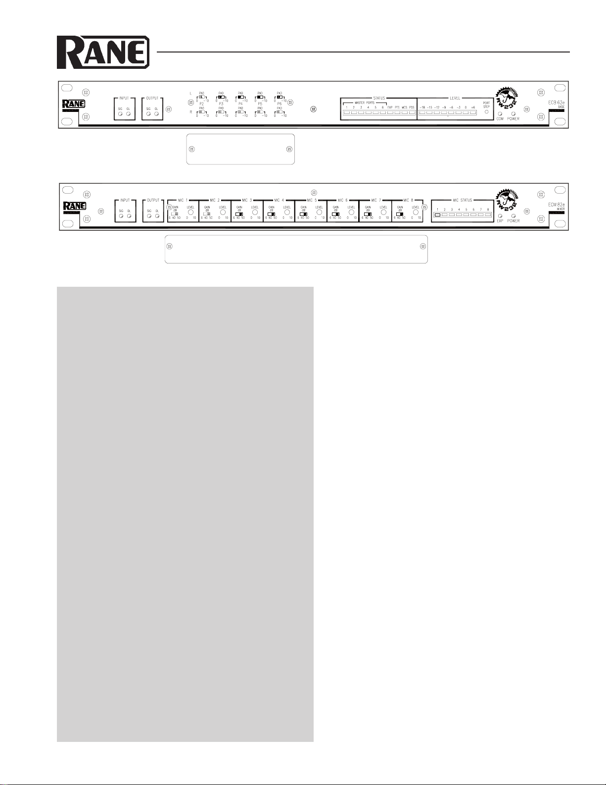
ECB 62e Base & Security Cover
ECM 82e Mixer & Security Cover
EC S HAR DWARE MAN UAL ECS
ENGINEERED CONFERENCE SYSTEMS
Quick Start
The ECS Operating Manuals are split into two booklets
— one for ECS hardware and one for RaneWare® software.
Neither booklet includes service information. Should any
unit require repair, contact the Rane factory. Telephone, fax
and web info is on the rear of this manual.
Typically, only one ECM 82eA (with AEC) is required
per system. If your system requires more than eight mics,
you can add up to five ECM 82e Mixers (without AEC) for
a total of 48 mics. The QuickAdapt™ algorithm allows a
single AEC to operate the entire system. When using a
single AEC with multiple mixers, daisy-chain the ECM 82e
Mixers together using MIX OUT to MIX IN. The last mixer
in the chain and the one that connects to the MIX 1 input on
the ECB 62e must be the ECM 82eA. Only the ECM 82eA
requires its AEC Reference input to be connected to the
Mono output on the ECB 62e. See RW Manual-17.
Plain Old Telephone Service (POTS) type teleconferencing, also know as phone add-on, requires an additional
Digital Hybrid. The Rane ECM 64e Conference System
with its DH 1e Digital Hybrid module can be added to
provide phone add-on support to the ECB 62e. If remote
diagnostics is desired, then add a Rane RPD 1 Programming
& Diagnostics unit or the Rane Via 10 Ethernet Bridge.
Since ECS is a programmable audio system, it must first
be programmed before it can pass audio. When power is
first applied to the ECB 62e, memory is set with all outputs
muted. For a typical system configuration, recall Memory 1
and inputs will be routed to outputs. To further simplify this
process, just recall Memory 16 and you are ready to adjust
mic levels. See RW Manual-21 for system setup procedures.
For more information there are four system applications in
the RaneWare Operators Manual.
Most echo problems are caused by improper microphone
placement and gain. To achieve good AEC performance, the
microphones must be properly set up, as shown on page
RW Manual-19 (in the ECS RaneWare Manual).
WEAR PARTS: This product contains no wear parts.
ECS Hardware Manual
This manual begins by explaining the options and
internal settings for each unit, since all optional accessories
must be installed and all internal jumpers set before
installation of the units into equipment racks. Next are
detailed descriptions of the front and rear panel features,
followed by detailed block diagrams and discussions, as
well as diagrams showing the signal flow making up the
critical “offsets,” or thresholds used by ECS. Then comes
instructions on Power, Audio & Data Connections, as well
as how to set each unit’s Device Address. Complete
electronic and mechanical specifications are found in the
Data Sheet.
Information on installing and running the control
software is found in the second booklet: ECS RaneWare
Operators Manual.
Contents
CUSTOMIZING ECS.................................................... 2
ECB 62e BASE ............................................................. 3
ECS 62 STEREO EXPANSION MODULE ............. 6
ECM 82e MIXER .......................................................... 7
ECA 2 ECHO CANCELLER MODULE ...................10
POWER, AUDIO, AND DATA CONNECTIONS ..11
SETTING THE DEVICE ADDRESS ........................13
U.S. Patent 5,848,146 on all Rane ECS products
Windows is a registered trademark of Microsoft Corporation
RaneWare is a registered trademark of Rane Corporation
HW Manual-1
Page 2
CUSTOMIZING ECS
Before installing ECS components, there are a few options
that need to be determined first. All but one of these require
removing the top covers before installation.
ECS 62 STEREO EXPANSION MODULE
See the description and installation diagram of the ECS 62
Stereo Expansion module into the ECB 62e Base on page HW
Manual-6. The ECS 62 installs by seating the card onto
factory installed standoffs on the motherboard.
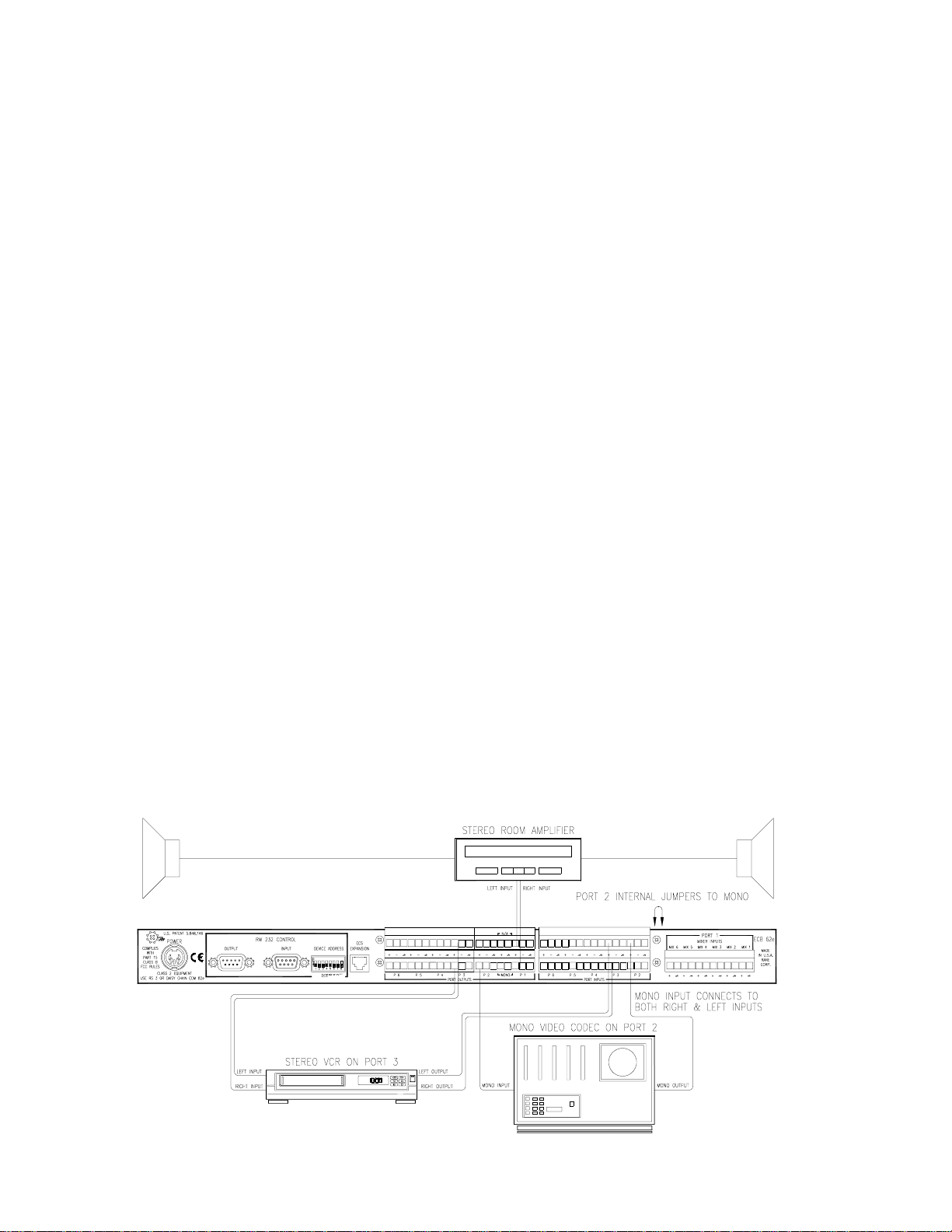
ECB 62e BASE WITH BOTH STEREO & MONO
PORTS
The ECB 62e Base and ECS 62 Stereo Expansion module
are shipped with jumpers in the stereo position. Both mono
and stereo sources may be used by changing the Mono
Jumper blocks as described on page HW Manual-6.
Mono Input signals must be wired to both the Left and
Right Inputs of the Base. Both Left and Right Port Outputs
produce the same mono signal. See Figure 1 below, and page
HW Manual-12 for mono source cable wiring.
Only the bottom ports (Right Channel) are monitored by
the Base. Therefore, threshold detection and metering are not
operational from the ECS 62.
ECM 82eA MIXERS WITH AEC
Systems may or may not require an AEC. Systems that do
require an AEC are those that require teleconferencing.
Although most video codec's have an AEC, their AEC
typically cannot operate with auto-mixers. It is always best to
use the ECM 82eA with a video codec. Systems not requiring
an AEC are those that only require speech reinforcement.
There are times you may wish to install multiple ECM
82eA’s. These are systems with a group of table microphones
where the General or Chairperson sits, and a group of ceiling
microphones or a gallery area. For these types of systems you
may want to set the table's ECM 82eA to soft suppression and
the other ECM 82eA to moderate or strong suppression. For
these types of systems connect each MIX OUT of the ECM
82eA to its respective MIX # input on the ECB 62e.
ECM 82e MIXER POST-GATE/PRE-GATE SWITCH
When installing a sound system with zones, it’s best to use
a Post-Gate mix of the Mics to create a Zone from the AUX
Output. This maintains the NOMM level for the Mixer. See
Applications - System 4 in the RaneWare Operators
Manual.
RaneWare note: the AUX Output is not turned On or Off
from the Mixer Output control.
This switch is set to Post-Gate at the factory. For installa-
tions requiring recording, place this switch in the Pre-Gate
position. This provides a more natural sounding recording.
This switch is located inside the ECM 82e Mixer. See the
diagram on page HW Manual-10.
ECM 82 MIXER PRE-AEC/POST-AEC SWITCH
Under normal circumstances a single AEC is used for the
entire system. When using a single AEC with multiple
mixers, daisy-chain the ECM 82e Mixers together using MIX
OUT to MIX IN. The last mixer in the chain and the one that
connects to the MIX 1 input on the ECB 62e must be the
ECM 82eA. For this type of configuration the MIX IN switch
on the ECM 82eA must be placed in its PRE-AEC position.
Rane ships the MIX IN switch on the ECM 82e in PRE-AEC
position.
The ECM 82e Mixer is shipped with the MIX IN (on the
rear panel) being mixed with the microphones before the
Echo Canceller. The internal MIX INPUT switch allows the
MIX IN to be combined with the microphone signals before
the Echo Canceller, thus providing echo cancellation to the
microphones of the upstream Mixer. To change to the Mix
Input to the pre-Echo Canceller setting, set the internal MIX
INPUT switch to the POST-AEC position. See the diagram on
page HW Manual-10 to locate the switch.
HW Manual-2
Figure 1. ECB 62e Base with both Stereo and Mono Ports
Page 3
ECB 62e BAS E
PORT 2
PORT 3
PORT 4
PORT 5
PORT 6
PORT 1
PORT 2
PORT 3
PORT 5
PORT 6
THE BASE
82e Mixers. The Base consists of a six port audio bridge, with
an optional internal ECS 62 Stereo Expansion module. The
Base can be used by itself as a six-by-six Port line-level audio
mixer and router. Bridging bases together creates more Ports.
ware controls are printed in bold san-serif type like this. See
the RaneWare Operators Manual for complete details.
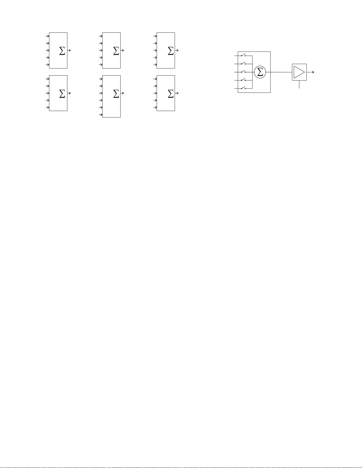
AUDIO BRIDGE
audio devices—thus the term six Port audio bridge. See
Figure 2 above. Each Input Port has both a hardware 10 dB
PAD switch on the front panel and software programmable
Input Attenuation controls. Each Output Port, except Port 5,
consists of a program selectable five input Audio Mixer/
Router and programmable Output Attenuation controls, as
shown in Figure 3. Port 5 has a program selectable six input
Audio Mixer/Router. This type of configuration for Ports 1-4
and 6 prevents the connection of an Input to its Output,
avoiding a possible feedback condition.
PORT 1
contains a six input line summer, connecting up to six Mixers.
All mics in the room are connected to this Port through the
ECM 82e Mixers. This Port contains a six input line mixer,
connecting up to six ECM 82e Mixers. See Figure 3.
It is designated as the Program Port, delivering audio to the
room sound system. It has both a balanced Right channel and
a summed Mono Output of Right and Left. An installed ECS
62 Stereo Expansion Module delivers the balanced Left
channel. The Mono Output connects to the Echo Canceller
Reference on all ECM 82e Mixers.
STATUS SIGNALS
62e front panel) contains the following Status indicators – all
of which can be obtained via RS-232 based room control
devices. (In the ECB 62e Device Control Language of the
1
2
3
4
5
1
2
3
4
5
PORT 1
PORT 3
PORT 4
PORT 1
OUT OUT OUT
PORT 5
PORT 6
PORT 1
PORT 2
PORT 3
PORT 4
OUT OUT OUT
PORT 4
PORT 6
PORT 5
1
2
3
4
5
1
2
3
4
5
6
PORT 2
PORT 5
PORT 1
PORT 2
PORT 4
PORT 5
PORT 6
PORT 1
PORT 2
PORT 3
PORT 4
PORT 5
1
2
3
4
5
1
2
3
4
5
Figure 2. ECB 62e Audio Bridge Figure 3. Port 1 Selection and Control
The ECB 62e Base is the master controller of the ECM
All functionality is controlled through RaneWare. Soft-
The audio bridge allows the connection of six full-duplex
The Port 1 Input is different from all other Ports. This Port
The Output of Port 1 is also different from all other Ports.
The top center of the ECS software screen (and the ECB
INPUT
PORT 3
PORT 6
PORT 2 (CODEC)
PORT 3 (AUX 1)
PORT 4 (AUX 2)
PORT 5 (VCR)
PORT 6 (PHONE)
SELECTS
PORT 1
OUTPUT
LEVEL
data
OUTPUT
ATTENUATION &
OUTPUT BUTTON
OFF = MUTE
RaneWare Operators Manual-29 refer to the RW 232 Command Get OPSTAT.)
The three Signal indicators – Program, Port and Mic – are
used within ECS to identify the current audio state of the
system, i.e., where audio is present or absent. The patented
performance advantages and much of ECS’s automatic
functionality is derived from the system being aware of these
indicators’ current state.
Program Signal indicator (PGS LED on the ECB 62e)
The Program indicator lights whenever audio is detected
at the Port 1 (Program) Output, thus indicating that audio
should be heard in the room. (If P3 Prog Contribute on the
System tab is checked, both Port 1 and Port 3 Outputs are
used to “sense” Program audio.
Port Signal indicator (PTS LED on the ECB 62e)
The Port indicator lights whenever audio is detected at any
Port Input whose Signal Mode is set to Automatic. This
includes mixer audio entering Port 1.
Mic Signal indicator (MCS LED on the ECB 62e)
This lights whenever audio is detected at any Active Mic
whose Mic Mode is set to Automatic.
Advanced auto power down example: Use the room
controller to monitor the Port and Mic Signal indicators.
When either is present, reset the power down timer that
eventually shuts down the system thus saving the projector
bulb, the associated power bill and actually save money!
Master Port
Identifies the current Master Port, which is the Port that
most recently detected audio. Use Master Port Delay on the
System tab for multipoint video applications.
Master Mic
Identifies the current Master Mic, which is the Mic that
most recently detected audio. A Master Mic is a status signal
generated when audio is detected at a Mic Input for a period
of time longer than the Master Mic Delay timer setting. If an
Input is assigned as Last On, and audio is detected for a
period longer than the Master Mic Delay timer, that Input
becomes the Master and remains on until a new Input takes
over. The old Master Mic then releases and returns to its set
Gate Depth. Use Master Mic Delay on the System tab for
video-follows-audio applications.
PROGRAM OUT
HW Manual-3
Page 4
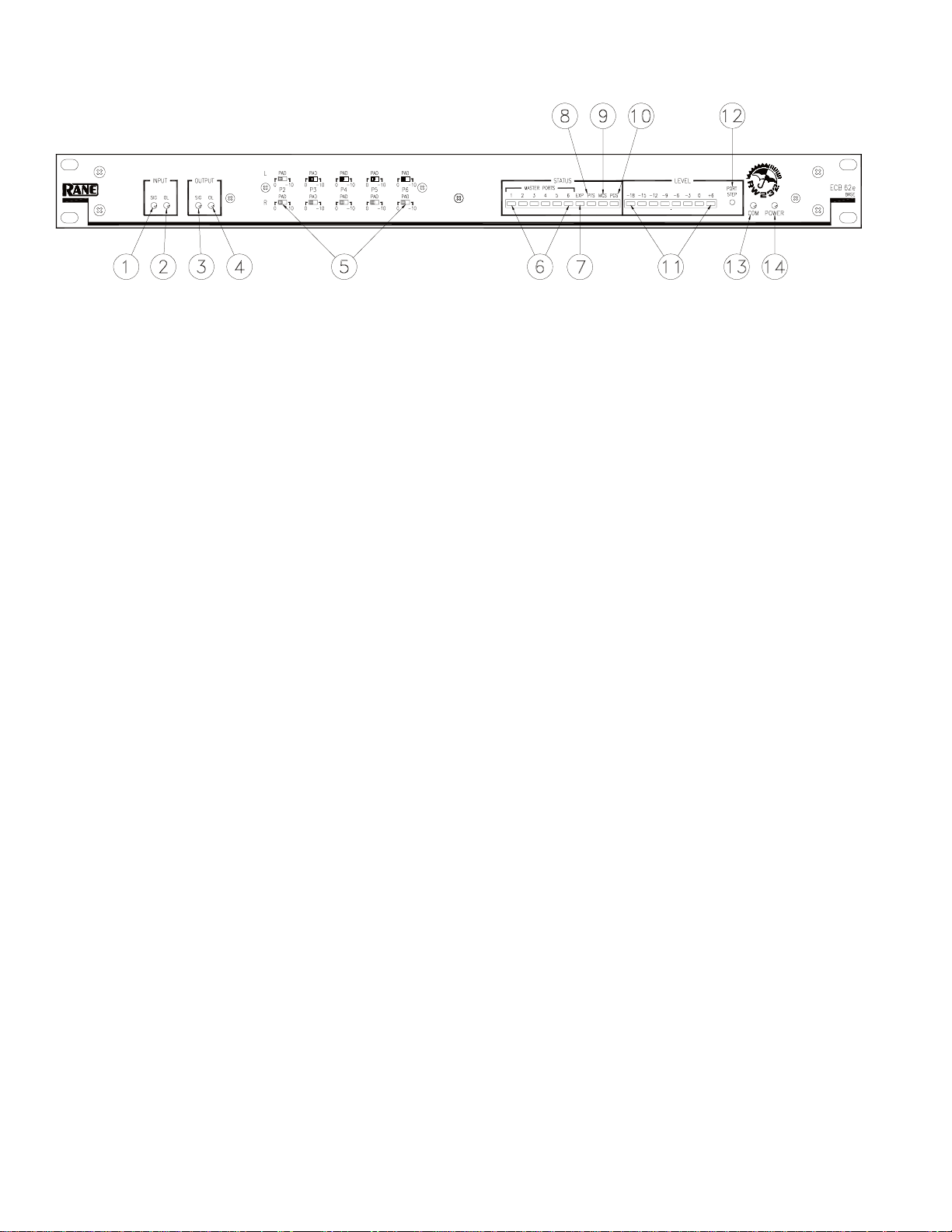
ECB 62e Base - Front Panel Description
INPUT SIG level indicator: Lights when the Input signal on any Port, before trim, is above -25 dBu. Use this to check
signal flow.
INPUT OL level indicator: Lights when the Input signal on any Port, before trim, is within 2 dB of clipping.
OUTPUT SIG level indicator: Lights when the Output signal on any Port is above -25 dBu. Use this to check signal flow.
OUTPUT OL level indicator: Lights when the Output signal on any Port is above 6 dBu.
INPUT PADs: Ports 2 through 6 have switch selectable 0 or –10 dB attentuation. Use –10 dB for pro audio devices with
0 dBu or greater output levels.
SYSTEM STATUS INDICATOR—MASTER PORTS: Displays the current Master Port. It is also used by the PORT
STEP button (see ) to display the current Port monitored by the LEVEL Meter.
EXP status indicator: EXPansion port data - Lights when receiving data from the ECM 82e Mixers.
PTS status indicator: PorT Signal - Lights when audio is detected at any Port.
MCS status indicator: MiC Signal - Lights when audio is detected at any Mic Input from any ECM 82e Mixer.
PGS status indicator: ProGram Signal - Lights when audio is detected at any Port Output.
LEVEL: VU meter Selectively displays all Port Inputs and Port 1 and 3 Outputs by using the PORT STEP (see ). This is
also an error display:
-3 by itself indicates an RW 232 receive parity error.
0 by itself indicates an Expansion Network overflow.
+6 by itself indicates an RW 232 overflow. During power-up initialization, this flashes until the system is ready.
If this keeps flashing longer than 10 seconds, RAM may be damaged. The ECB 62e needs servicing.
If this illuminates steadily, the system has overflowed. To remedy, cycle the power off, then back on.
PORT STEP button: Pressing this for 1 second causes the MASTER PORT STATUS LED to flash the currently moni-
tored port for the LEVEL meter. If this button is pressed and held for 5 seconds, the monitored Port can be incremented by
pressing the button in 1 second steps. The MASTER PORT STATUS LEDs will step Port 1 thru Port 6 Inputs (LED 1-6),
then back for the Port 1 Output (LED 1), then the Port 3 Output (LED 3), and then returning back to Port 1’s Input (LED 1).
COM indicator: flashes randomly when receiving valid data from the control system or PC. If the DEVICE ADDRESS is
not within a valid range (1-250), this LED flashes steadily at ½ second intervals.
POWER indicator: Lights when the Base’s operating system is running.
HW Manual-4
Page 5
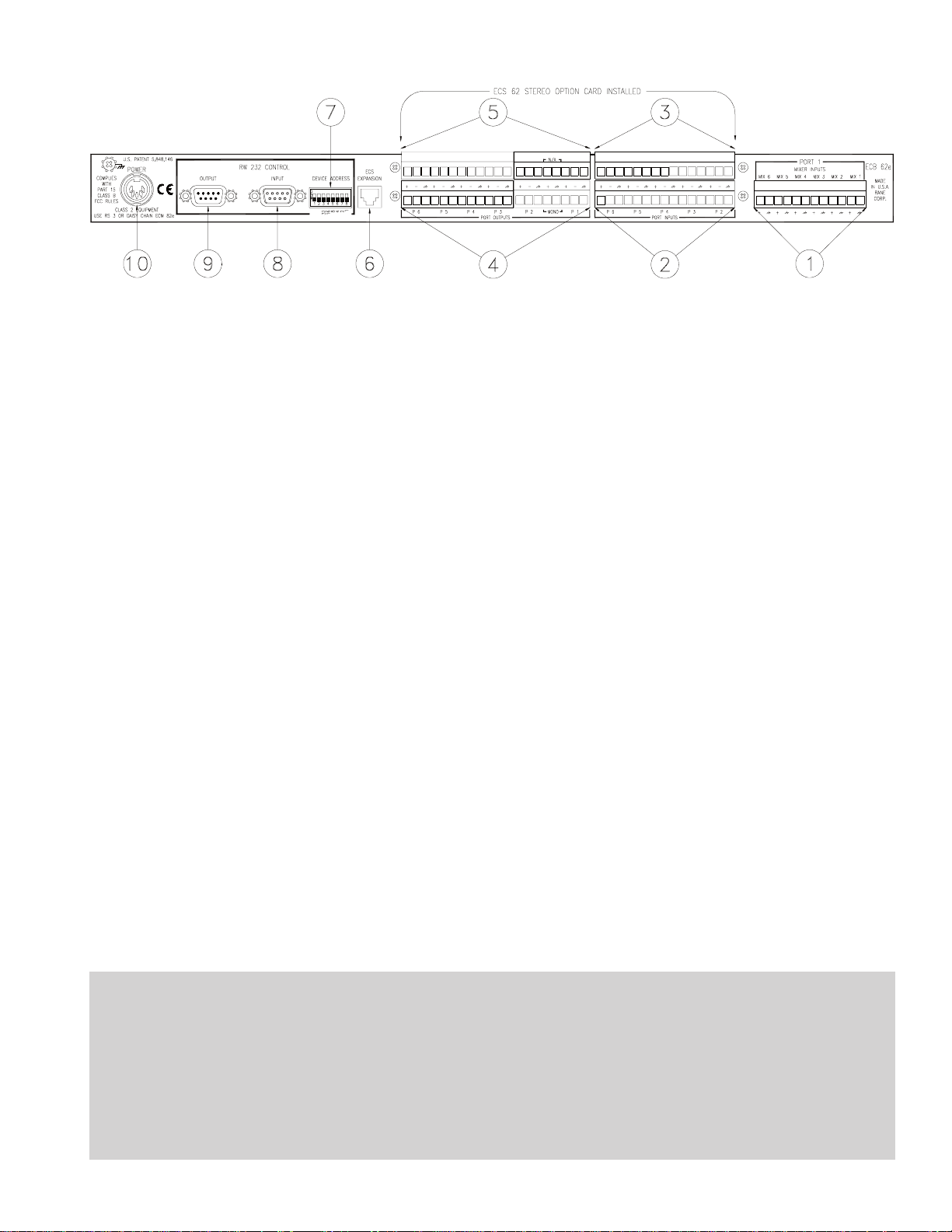
ECB 62e Base - Rear Panel Description
PORT 1 MIXER INPUTS: MIX 1 thru MIX 6 connect to the MIX OUTs of the ECM 82e Mixers via the 12-pin
Euroblock.
PORT INPUTS: P2 thru P6 connect to balanced line sources via this 15-pin Euroblock. When the ECS 62 Stereo Option
card is installed, these are the Right channel Inputs. See page HW Manual-6.
ECS 62 PORT INPUTS: Connects the Left channel Inputs. See page HW Manual-6.
PORT OUTPUTS: This 8-pin Euroblock provides P1, P1 MONO and P2 Outputs, and the 12-pin Euroblock provides P3
thru P6. (P1 MONO is used for the ECM 82e Echo Canceller Reference.) When the ECS 62 Stereo Option card is installed,
these are the Right channel Outputs.
ECS 62 PORT OUTPUTS: Connect the Left channel P1 and P2 Outputs from the 8-pin Euroblock, while P3 thru P6 are
delivered from the 12-pin Euroblock. (P1 Mono Not Applicable—available at .)
ECS EXPANSION port: This RJ12 mod jack and cable (included) is an Expansion data interface to control and communi-
cate with the ECM 82e Mixers. This proprietary high speed data interface cannot be used with non-ECS products. During
power-up of the Base, all connected Mixers are polled, then sent their respective data, from the Base’s non-volatile memory.
The Base then polls the Mixers at one minute intervals checking for dropped or added mixers. If found, the Base resets.
RW 232 CONTROL - DEVICE ADDRESS: Sets the RW 232 address for the ECB 62e. Each RW 232 unit requires a
different address. If the RW 232 Control Device Address is set to an invalid address, the COM LED continually flashes.
The Device Address can be changed without power cycling the unit. See page HW Manual-13.
RW 232 CONTROL - INPUT: This DB-9 female connects to the RS-232 output of the controller (or PC), or the OUTPUT
of another RW 232 unit connected to the controller. Rane uses a standard RS-232 interface using Rane’s RW 232 protocol
operating at 19.2 kb. Units connect by daisy-chaining the products on a serial bus, OUTPUT to INPUT.
RW 232 CONTROL - OUTPUT: This DB-9 male connects to downstream RW 232 units.
POWER input jack: This 5-pin DIN connects to the included RS 3 power supply, or daisychained with the Power Loop
cable from the ECM 82e connected to the RS 3 power supply. Warning! Connect the power supply DIN connector to the
Base BEFORE connecting to AC power, otherwise damage may occur. See page HW Manual-11. A maximum of 3 units
may be daisy chained off of one RS 3 power supply (1 ECB 62e Base and 2 ECM82e Mixers or 3 ECM 82e Mixers).
ECB 62e Installation Notes
If an ECS 62 Stereo card is to be installed in the ECB 62e, install the required mono jumper on the ECB 62e mother
board before installing the ECS 62 (see page HW Manual-6).
The ECS Expansion port is the control between the ECB 62e and the ECM 82e’s. Using the supplied RJ12 cable
connect the ECM 82es to the ECB 62e. Note: The ECM 82e’s do not use RW 232 addressing. The ECS address for the
ECM 82es determines the Mic number on the ECM 82e. ECS address 1 is Mixer 1, Mics 1 thru 8. ECS address 6 is Mixer
6, Mics 41 thru 48. Only use termination on the last Mixer when using four or more Mixers. ECS termination is located
inside the ECM 82e.
HW Manual-5
Page 6
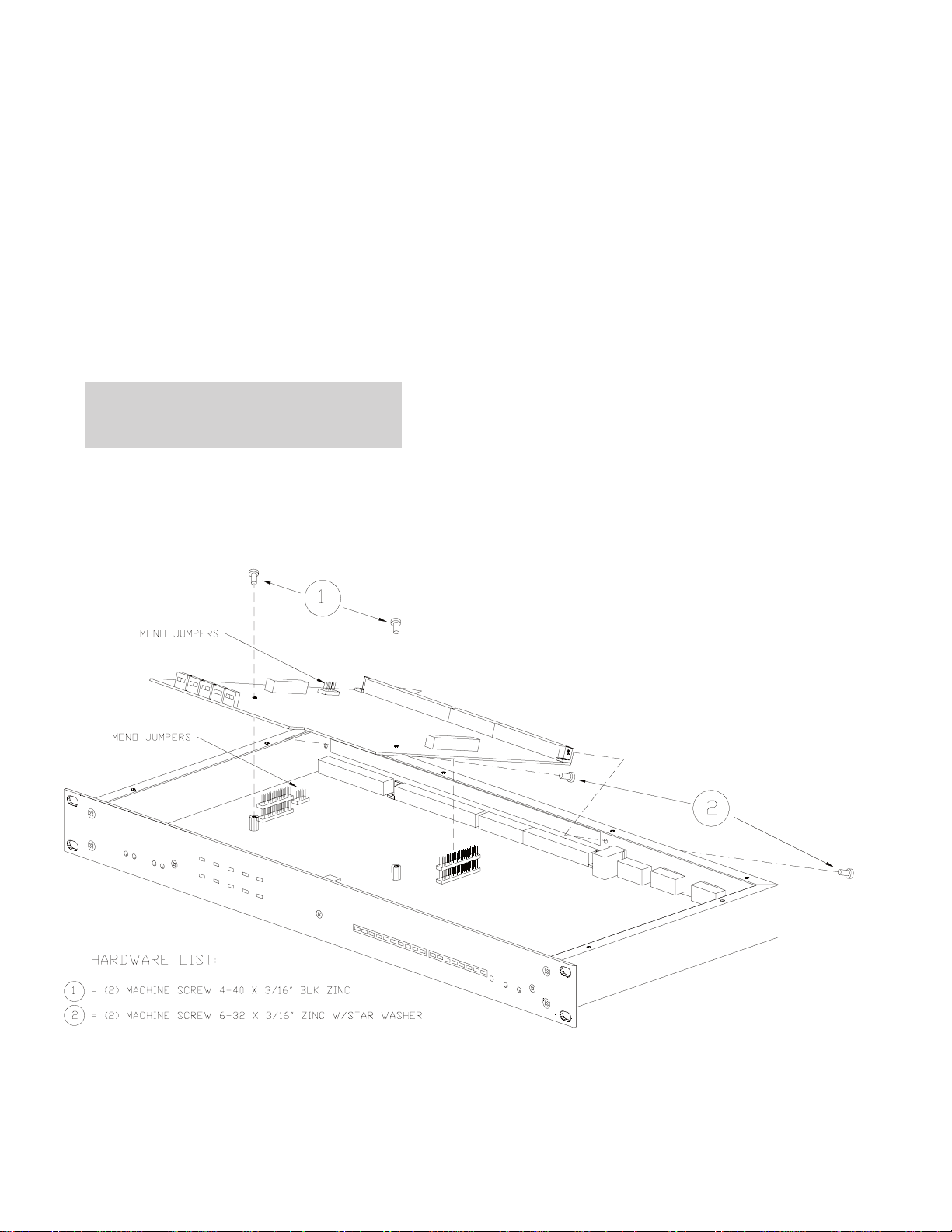
ECS 62 STE R EO E XPAN SION M OD ULE
DESCRIPTION
The ECS 62 is a plug-in module for the ECB 62e Base.
Once installed, the Base can accommodate both stereo and
mono audio. Included on the module is a duplicate of the
Base’s Audio Bridge, with the exception that Port 1 has no
external input connection, and the Mono Program Output is
eliminated. The stereo module mounts on top of the ECB 62e
motherboard and is designated as the Left channel.
The ECS 62 installs by temporarily removing the top
cover of the ECB 62e and seating the card onto factory
installed standoffs on the motherboard. See Figure 8 below.
Warning: Proper static discharge measures must be
followed when installing or configuring this card.
ECS 62 LEFT CHANNEL FEATURES
• Six Port Selective Audio Bridge, control is combined with
the ECB 62e Right channel Audio Bridge.
• Hardware Pad switches set Input attenuation on Ports 2-6.
• Software Programmable Level controls on all Inputs and
Outputs combined with the Base’s Right channel Levels.
• Port 1’s mono inputs deliver signal to both Right and Left
channels of Port 1.
• Internal hardware jumpers provide mono Outputs.
STEREO & MONO OPERATION
Both mono and stereo equipment are accommodated by
installing the ECS 62 into the ECB 62e and placing the
internal Mono Output jumpers to their “mono” positions for
mono equipment. Mono Input signals must be wired to both
the Left and Right Inputs of the Base. Both Left and Right
Port Outputs produce the same mono signal. See page
Manual-12 for mono source cable wiring.
Since Port 1 is designated as the Program Output, it does
not have a Mono jumper. Both mono and stereo Outputs are
provided simultaneously from Port 1.
Note: Audio levels from the ECS 62 are not monitored by
the ECB 62e Base.
HW Manual-6
Figure 7. ECS 62 Stereo Expansion Card installation with Mono Jumper locations
Page 7

ECM 82e MIXE R
The ECM 82e Mixer is a digitally-controlled-analog
8- channel Mic/Line auto-mixer. An optional internal DSP
Echo Canceller module is available either separately (model
ECA 2) or included (model ECM 82eA). Each Base supports
up to 6 Mixers, allowing 48 Inputs. All system parameters of
the Base and Mixers are stored within the Base using nonvolatile memory (no batteries). The ECM 82e Mixer is not a
stand-alone device and will not operate without a Base
connected.
All functionality is controlled through RaneWare. Software controls are printed in this manual in san-serif type like
this. See the RaneWare Operators Manual for details.
LAST-ON or GATED MODES
Unique among automatic mic mixers, each Mic can be
independently set to Last On or Gated. A Mic assigned as
Gated simply opens the mic when the input signal is above
the Threshold Level, and returns to its Gate Depth when the
signal drops below the Threshold Level and the Release
Timer has expired. A Mic assigned as Last On remains on
once it becomes the Master Mic.
This is useful in boardrooms where the head table would
require last-on mics and the audience area requires gated
mics. This way, the board members (and their background
noise) are always heard, while the less-often used audience
(i.e., questions) mics, gate off when not in use. Rane has
patented this concept – the marketing buzz word being Smart
Last On™. Having an open mic also maintains the full duplex
awareness of the conference.
MZEC™ (em-zeck)
Using large auto mixers with an echo canceller can cause
echo problems when several microphones gate-on at the same
time. If a single Echo Canceller is adapting to all Mic signals,
and more than three Mics are on at the same time, the acoustic
model for the room may become too complex. This causes
Echo Canceller divergence, resulting in more suppression or
return echo. To eliminate this problem, each ECM 82e Mixer
allows the addition of an internal Acoustic Echo Canceller.
Placing an Echo Canceller in each mixer reduces the number
of acoustical echo paths for a multi-microphone system,
improving the system audio quality. (See the ECA 2 Acoustic
Echo Canceller module on page HW Manual-10.) This
method is called MultiZone Echo Cancelling (MZEC™).
Important: The ECB 62e PORT 1 MONO OUTPUT must
be connected to all the E/C REF Inputs of the ECM 82e
Mixers.
QuickAdapt™
The QuickAdapt algorithm allows a single AEC to operate
the entire system. This algorithm uses the Rane exclusive
Smart Last On™ feature to precondition the AEC for a
microphone gate change. This feature can be disabled by
setting a Mic Gate Depth to 0 dB on the ECM 82eA. If you
want to maintain the QuickAdapt algorithm, but you also
want to keep a microphone opened, set the Mic Gate Depth to
-1 dB. Another QuickAdapt feature is to precondition the
AEC for a microphone mute condition. This allows standard
Push-To-Talk microphones to be used.
PHANTOM POWER
The ECM 82e Mixer is shipped with the Phantom Power
switches in the “on” position. To change, locate the Phantom
Power switches on the rear panel of the unit and select the
“off” position when you don't want phantom power.
The ECM 82e Mixer is shipped with an internal switch
selecting 24v Phantom Power. 12v Phantom power may be
selected by changing the internal switch from 24v to 12v. See
the diagram on page HW Manual-10 to locate the switch.
REDUCING NOISE AND ACOUSTIC GAIN
To reduce noise and acoustic gain due to the mixing of
multiple microphones, the ECM 82e uses a special NOMM
Mode (Number Of Mics per Mixers open). This function
maintains full level at the loudest Mic Input while reducing
Gains of the other Mics in order to keep unity gain. Turning
on this feature also enables a limiter for each Mic channel.
DEVICE ADDRESS
The Mixer’s rear panel ECS INTERFACE DEVICE
ADDRESS determines its Mixer number and Mic Input
numbers. For example, Device Address 1 is Mixer 1 including
Mics 1-8, and Device Address 2 is Mixer 2 including Mics 9-
16. Only Device Addresses 1 through 6 are allowed, since this
is the maximum Mixers per Base. When a Mixer is first
powered up and has not received data from the Base, the Mic
Status LEDs display the Mixer Device Address.
An invalid Device Address set on the Mixer causes its
COM LED to continually flash. The ECM 82e’s power must
be cycled after changing the Device Address. Unplug from
the wall, not the unit!
HW Manual-7
Page 8

ECM 82e Mixer - Front Panel Description
INPUT SIG indicator: Lights when any Input signal, before trim, is above -25 dBu. Use to check signal flow.
INPUT OL indicator: Lights when the Input signal on any Input, before trim, is within 2 dBu of clipping. Watch this when
Selecting the Input GAIN and setting the LEVEL.
OUTPUT SIG indicator: Lights when the Mix Output signal is above -25 dBu. Use to check signal flow.
OUTPUT OL indicator: Lights when the Mix Output signal level is 2 dBu before clipping.
MIC GAIN switch: Selects between +6 dB (line level), +40 dB (most mics), or +56 dB.
MIC LEVEL trim: Use a small flat screwdriver to adjust the Level from off to full on.
MIC STATUS indicators: Displays the status of the Mic gate: A flashing LED indicates the Mic is Gated On, or the Mic is
the Master Mic for this Mixer. A continuous LED indicates the Mic is the system’s Master Mic. When power is first applied,
the ECM 82e displays its DEVICE ADDRESS until it receives data from the ECB 62e. Once data is received, the ECM 82e
lights LEDs 1, 2, and 6 for about 1 second.
EXP indicator: Lights when receiving Expansion Data.
POWER indicator: Lights when the processor is operating properly.
ECM 82e Installation Notes
If Phantom Power is not required remove the top cover to the ECM 82e and disable it. See page HW Manual-10.
Always leave the RS 3 power supplies for last. Once all the wiring is completed, connect the loop thru power cables
between the ECM 82es ending at the ECB 62e. Before connecting the RS 3 make certain that it is not connected to the AC
power. See page HW Manual-11.
The ECS Expansion port is the control between the ECB 62e and the ECM 82es. Using the supplied RJ12 cable
connect the ECM 82es to the ECB 62e. Note: The ECM 82es do not use RW 232 addressing. The ECS address for the ECM
82es determines the Mic number on the ECM 82e. ECS address 1 is Mixer 1, Mics 1 thru 8. ECS address 6 is Mixer 6, Mics
41 thru 48.
HW Manual-8
Page 9
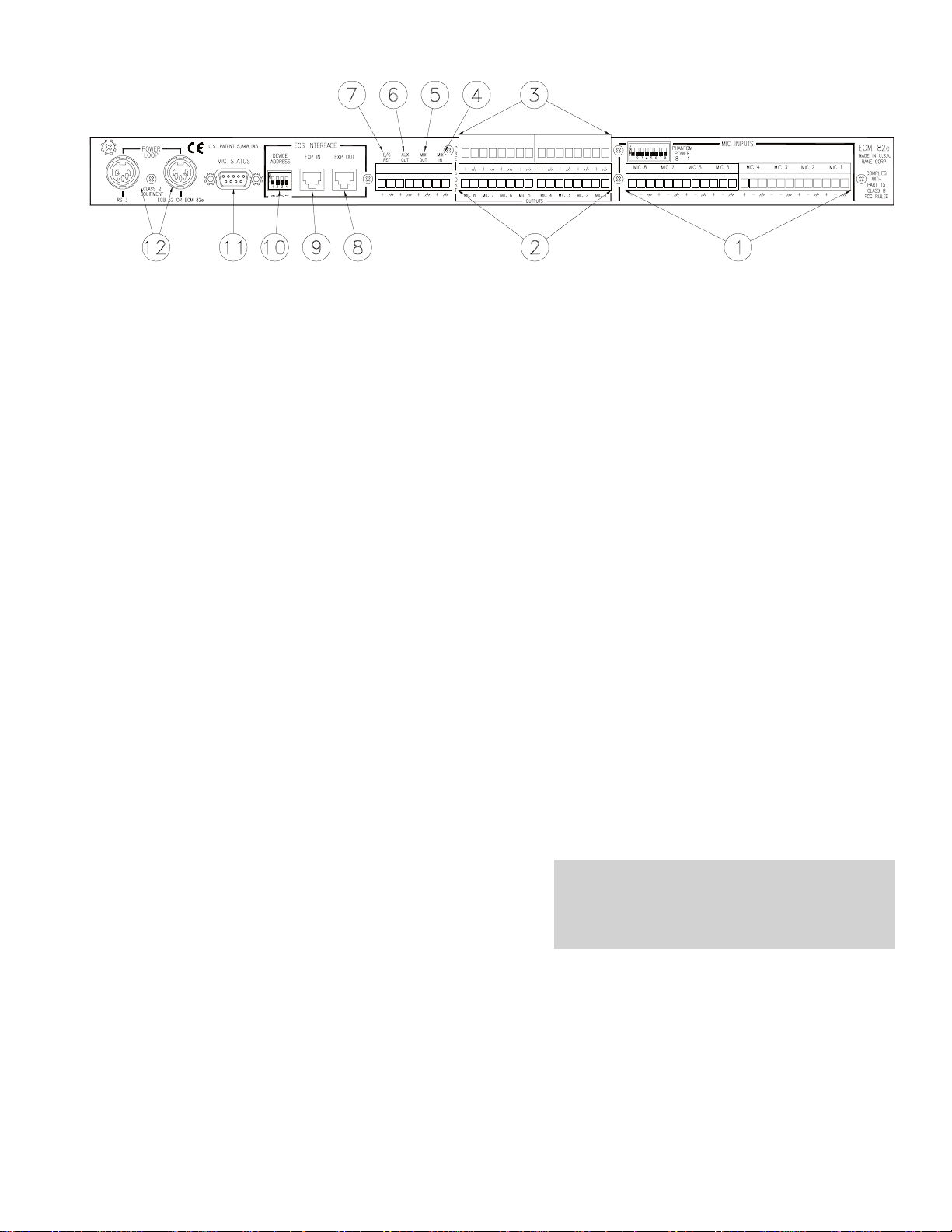
ECM 82e Mixer - Rear Panel Description
MIC INPUTS: These balanced Inputs connect MIC 1-MIC 4 on one 12-pin Euroblock, and MIC 5-MIC 8 on another 12-
pin Euroblock. See page HW Manual-12 for cable wiring.
POST-GATE OUTPUTS: One 8-pin Euroblock delivers MIC 1-MIC 4; the other 8-pin Euroblock delivers MIC 5-MIC 8.
PRE-GATE OUTPUTS: One 8-pin Euroblock delivers MIC 1-MIC 4; the other 8-pin Euroblock delivers MIC 5-MIC 8.
MIX IN: This input can be mixed as either PRE-AEC or POST-AEC. For single AEC applications use the PRE-AEC
setting (factory default), (see figure 11, next page).
MIX OUT: This Post-Gate Output is program Selectable as either a Pre-Echo-Canceller or Post-Echo-Canceller, and is
typically connected to one of the MIX INPUTs on the ECB 62e Base. For Pre-Echo Cancellation, Select Bypass in the
Echo Canceller box on the Mixer’s page in RaneWare.
AUX OUT: This Output is switch selectable as either a Post-Gate or Pre-Gate before the Echo Canceller. This switch is set
to “Post-Gate” at the factory. If required, remove the top cover and look for the switch marked “S1” in the middle toward the
back of the circuit board. Set the switch according to the silkscreen and replace the cover and screws.
E/C REF: Echo Canceller Reference—This Input typically connects to the Port 1 MONO Output of the ECB 62e Base when an
ECA 2 Echo Canceller is used within this Mixer. The average signal level at this input must be between -10 and 0 dBu.
ECS INTERFACE—EXP OUT: This RJ12 mod jack (and supplied cable) sends Expansion data, connecting to the EXP
IN jacks on subsequent ECM 82e Mixers.
ECS INTERFACE—EXP IN: This RJ12 mod jack (and supplied cable) receives Expansion data, connecting to the ECS
EXPANSION jack on the ECB 62e Base or the EXP OUT jacks on upstream ECM 82e Mixers.
ECS INTERFACE—DEVICE ADDRESS: Selects the Mixer number 1 thru 6. The Device Address is set using a binary
code determined using the following table. For example, turning ON the switches labeled ‘1’ and ‘2’ on the chassis yields
address ‘3’. In the following table, 0 means switch down (OFF), 1 means switch up (ON).
SWITCH #s 1234
1 0001
2 0010
DEVICE 3 0011
ADDRESS 4 0100
5 0101
6 0110
SILKSCREEN #s 8421
An invalid Device Address set on the Mixer causes
its COM LED to continually flash. The ECM 82e’s
power must be cycled after changing the Device
Address. Unplug from the wall, not the unit!
MIC STATUS: This DB-9 female jack is an open collector Output reflecting the current Master or Gated Mic. A new
Master or Gated Mic causes its corresponding pin to go low for 50 milliseconds. Pin 1 is Mic 1, pin 2 is Mic 2, pin 3 is Mic
3… and pin 9 is ground. This connector can provide status information for video-follows-audio.
POWER LOOP: A DIN cable (included) connects up to three ECM 82 Mixers and one ECB 62e Base, powered from one
RS 3 Power Supply. Connect only a Rane RS 3 power supply to either of these DIN jacks or an attached unit with an RS 3.
Do not connect two RS 3 units to the same unit or loop. Warning! Connect the DIN power supply connectors to the
units before connecting to AC power, otherwise damage may occur. See POWER on page HW Manual-11. A maximum of
3 units may be daisy chained off of one RS 3 power supply (1 ECB 62e Base and 2 ECM82e Mixers or 3 ECM 82e Mixers).
HW Manual-9
Page 10

ECA 2 E CHO CAN C E LLE R MOD U LE
DESCRIPTION
The ECA 2 is a continually adaptive Acoustic Echo
Canceller module for the ECM 82e Mixer using the Rane
QuickAdapt™ algorithm. The ECM 82eA Mixer is shipped
with the ECA 2 installed. The QuickAdapt algorithm allows a
single AEC to operate the entire system. This algorithm uses
the Rane exclusive Smart Last On™ feature to precondition
the AEC for a microphone gate change. This feature can be
disabled by setting a Mic Gate Depth to 0 dB on the ECM
82eA. If you want to maintain the QuickAdapt algorithm, but
you also want to keep a microphone opened, set the Mic Gate
Depth to -1 dB. Another QuickAdapt feature is to precondition the AEC for a microphone mute condition. This allows
standard Push-To-Talk microphones to be used. When using
the single AEC method, daisy-chain the Mixers by connecting
MIX OUT to MIX IN on the with the last connection before
the ECB 62e being the ECM 82eA. Only the ECM 82eA
requires its AEC Reference input to be connected.
Multiple ECM 82eA mixers can also be used in situations
where areas in the room are different. For example, table
microphones may only require soft suppression, while ceiling
microphones may require moderate or strong suppression.
This method of echo cancelling is called MZEC™ MultiZone
Echo Cancelling. When using multiple ECM 82eA mixers,
connect the MIX OUT of each mixer to its respective MIX #
input on the ECB 62e.
Since the Echo Canceller automatically adapts to the
room, training is not required.
To upgrade an ECM 82e to an ECM 82eA install the
ECA 2 by temporarily removing the top cover of the
ECM 82e and seating the module onto factory installed
standoffs on the motherboard. After installing the Echo
Canceller, disable Echo Canceller Bypass in RaneWare (see
the RaneWare Operators Manual).
POST-GATE MIX
Σ
Figure 10. ECA 2 Block Diagram (detail from Data Sheet Block Diagram).
Warning: Proper static discharge measures must be
OPTIONAL
ECA 2 MODULE
ECHO CANCELLER
TRANSMITINTRANSMIT
IN OUT
RECEIVE
CTRL.
POST-GATE
PRE-GATE
E/C BYPASS
Σ
+4dB
followed when installing or configuring this card.
OUTPUT
SIG/OL
DETECTOR
OL
SIG
-14dBu
MIX
301
301
OUT
-10dBu
AUX
OUT
HW Manual-10
Figure 11. ECA 2 Installation with ECM 82e Phantom Power and network termination jumper locations
Page 11
PO WER, AU DI O, & DATA CO NN E CTION S
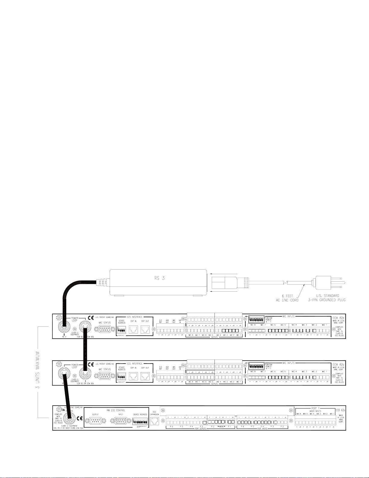
POWER
The Rane RS 3 Power Supply is provided with each
ECB 62e Base, and required for operation of the ECM 82e
Mixer. Daisychaining is possible with the DIN cables
(included with the ECM 82e). One RS 3 will power any one
of the following:
• (1) Base and (2) Mixers
• (3) Mixers
When connecting the ECS units to other components in
your system for the first time, leave the power supplies for
last, and then connect the DIN power cable to the unit
BEFORE connecting AC power. This gives you a chance to
correct any mistakes before any damage is done to your units,
speakers, computer, ears, etc.
AUDIO
ECS units have both balanced and unbalanced Inputs and
Outputs, with chassis-grounded shields. Chassis ground is to
be connected to a known earth ground. Refer to Figure 13 on
the following page.
DATA
To control the units from a computer, use nine-pin RS-232
cables 50 feet or shorter. The cable must not be a null-modem
type. A short cable is supplied for connecting adjacent units.
Daisychain up to 16 units by connecting the COM port on the
computer to the INPUT connector on the first unit, and the
OUTPUT connector of each unit to the next unit’s INPUT.
Since RS-232 can pass through RW 232, additional RS-232
devices may be attached at the end of the RW 232 chain. See
the pin-outs in Figure 13 on the following page.
DETAILS
Large racks of equipment such as ECS may generate
excess heat, requiring extra space beween units, and/or forced
air ventilation to reduce the ambient temperature in the rack.
Before powering the units, set the DEVICE ADDRESS
switches as shown on page HW Manual-13.
OK, now for the AC line cord.
Figure 12. RS 3 daisychained power connections
HW Manual-11
Page 12

Unbalanced source to balanced ECB 62e Input, 2-conductor cable with shield
Unbalanced source to balanced ECB 62e Input, 1-conductor cable with shield
Balanced ECB 62e Output to an unbalanced unit
Balanced mono source to a stereo ECB 62e
Balanced mono source to a stereo ECB 62e with transformer type termination
AMX AX 232 to ECB 62e - Euroblock to DB-9 malePC to ECB 62e - DB-25 female to DB-9 malePC to ECB 62e - DB-9 female to DB-9 male
HW Manual-12
Figure 13. ECS cable wiring
Page 13

SET TI NG TH E D E VICE AD D RE SS
The Device Address is set using a binary code which may be determined using the following
table, our Windows Address Calculator program, or by adding the place values (1-128)
silkscreened on the chassis. Ignore all numbers printed directly on the switch. For example,
turning ON the switches labeled ‘1’ and ‘2’ yields address ‘3’. In the following table, 0 means
switch down (OFF), 1 means switch up (ON), and the left-most digit corresponds to the switch
labeled ‘128’.
Rane also provides a special calculator to assist in setting the dip switches. After installing
the software, in the RaneWare program group, launch the RaneWare 232 Address Calculator.
This binary calculator converts decimal numbers into corresponding dipswitch settings.
Figure 14. Device Address Calculator
1 00000001
2 00000010
3 00000011
4 00000100
5 00000101
6 00000110
7 00000111
8 00001000
9 00001001
10 00001010
11 00001011
12 00001100
13 00001101
14 00001110
15 00001111
16 00010000
17 00010001
18 00010010
19 00010011
20 00010100
21 00010101
22 00010110
23 00010111
24 00011000
25 00011001
26 00011010
27 00011011
28 00011100
29 00011101
30 00011110
31 00011111
32 00100000
33 00100001
34 00100010
35 00100011
36 00100100
37 00100101
38 00100110
39 00100111
40 00101000
41 00101001
42 00101010
43 00101011
44 00101100
45 00101101
46 00101110
47 00101111
48 00110000
49 00110001
50 00110010
51 00110011
52 00110100
53 00110101
54 00110110
55 00110111
56 00111000
57 00111001
58 00111010
59 00111011
60 00111100
61 00111101
62 00111110
63 00111111
64 01000000
65 01000001
66 01000010
67 01000011
68 01000100
69 01000101
70 01000110
71 01000111
72 01001000
73 01001001
74 01001010
75 01001011
76 01001100
77 01001101
78 01001110
79 01001111
80 01010000
81 01010001
82 01010010
83 01010011
84 01010100
85 01010101
86 01010110
87 01010111
88 01011000
89 01011001
90 01011010
91 01011011
92 01011100
93 01011101
94 01011110
95 01011111
96 01100000
97 01100001
98 01100010
99 01100011
100 01100100
101 01100101
102 01100110
103 01100111
104 01101000
105 01101001
106 01101010
107 01101011
108 01101100
109 01101101
110 01101110
111 01101111
112 01110000
113 01110001
114 01110010
115 01110011
116 01110100
117 01110101
118 01110110
119 01110111
120 01111000
121 01111001
122 01111010
123 01111011
124 01111100
125 01111101
126 01111110
127 01111111
128 10000000
129 10000001
130 10000010
131 10000011
132 10000100
133 10000101
134 10000110
135 10000111
136 10001000
137 10001001
138 10001010
139 10001011
140 10001100
141 10001101
142 10001110
143 10001111
144 10010000
145 10010001
146 10010010
147 10010011
148 10010100
149 10010101
150 10010110
151 10010111
152 10011000
153 10011001
154 10011010
155 10011011
156 10011100
157 10011101
158 10011110
159 10011111
160 10100000
161 10100001
162 10100010
163 10100011
164 10100100
165 10100101
166 10100110
167 10100111
168 10101000
169 10101001
170 10101010
171 10101011
172 10101100
173 10101101
174 10101110
175 10101111
176 10110000
177 10110001
178 10110010
179 10110011
180 10110100
181 10110101
182 10110110
183 10110111
184 10111000
185 10111001
186 10111010
187 10111011
188 10111100
189 10111101
190 10111110
191 10111111
192 11000000
193 11000001
194 11000010
195 11000011
196 11000100
197 11000101
198 11000110
199 11000111
200 11001000
201 11001001
202 11001010
203 11001011
204 11001100
205 11001101
206 11001110
207 11001111
208 11010000
209 11010001
210 11010010
211 11010011
212 11010100
213 11010101
214 11010110
215 11010111
216 11011000
217 11011001
218 11011010
219 11011011
220 11011100
221 11011101
222 11011110
223 11011111
224 11100000
225 11100001
226 11100010
227 11100011
228 11100100
229 11100101
230 11100110
231 11100111
232 11101000
233 11101001
234 11101010
235 11101011
236 11101100
237 11101101
238 11101110
239 11101111
240 11110000
241 11110001
242 11110010
243 11110011
244 11110100
245 11110101
246 11110110
247 11110111
248 11111000
249 11111001
250 11111010
HW Manual-13
Page 14

FCC NOTICE
This equipment has been tested and found to comply
with the limits for a Class B digital device, pursuant to Part
15 of the FCC Rules. These limits are designed to provide
reasonable protection against harmful interference when the
equipment is operated in a residential installation. This
equipment generates, uses, and can radiate radio frequency
energy and, if not installed and used in accordance with the
instructions, may cause harmful interference to radio
communications. However, there is no guarantee that
interference will not occur in a particular installation. If this
equipment does cause harmful interference to radio or
television reception, which can be determined by turning
the equipment off and on, the user is encouraged to try to
correct the interference by one or more of the following:
1. Re-orient or relocate the receiving antenna.
2. Increase the separation between the equipment and the
receiver.
3. Connect the equipment into an outlet on a circuit different from that to which the receiver is connected.
4. Consult the dealer or an experienced radio/TV technician.
CANADIAN EMC NOTICE
This Class B digital apparatus meets all requirements of
the Canadian Interference-Causing Equipment Regulations.
Cet Appariel numerique de la classe B respecte toutes
les exigences du Reglement sur le material broilleur du
Canada.
CHASSIS GROUNDING
If after hooking up your system it exhibits excessive
hum or buzzing, there is an incompatibility in the grounding
configuration between units. Here are some things to try:
1. Try combinations of lifting grounds on units supplied
with ground lift switches (or links).
2. Verify all chassis are tied to a good earth ground.
3. Some units with outboard power supplies do not ground
the chassis through the line cord. Make sure these units
are solidly grounded by tying the Chassis Ground Point
to known earth ground. Use a star washer to guarantee
proper contact.
©Rane Corporation 10802 47th Ave. W., Mukilteo WA 98275-5098 TEL (425)355-6000 FAX (425)347-7757 WEB http://www.rane.com
HW Manual-14
104807
 Loading...