

DATA SHEET
BYPASS1STORE
RECALL
CHAN
MILLISECONDS
MODE
MEMORY
2 A B
DISPLAY
21
1 ms
10 μs
1 2
SIGNAL CLIP
dBu
SIGNAL
SENSITIVITY SENSITIVITY
CLIP
dBu
0 -16
+4 -20
-4 -12
-8
0 -16
+4 -20
-4 -12
-8
AD 22d
METERS
FEET
AUDIO DELAY
-10 dBV
-10 dBV
HOLD TO SET TEMP
COARSE
FINE
°C °F
260.45
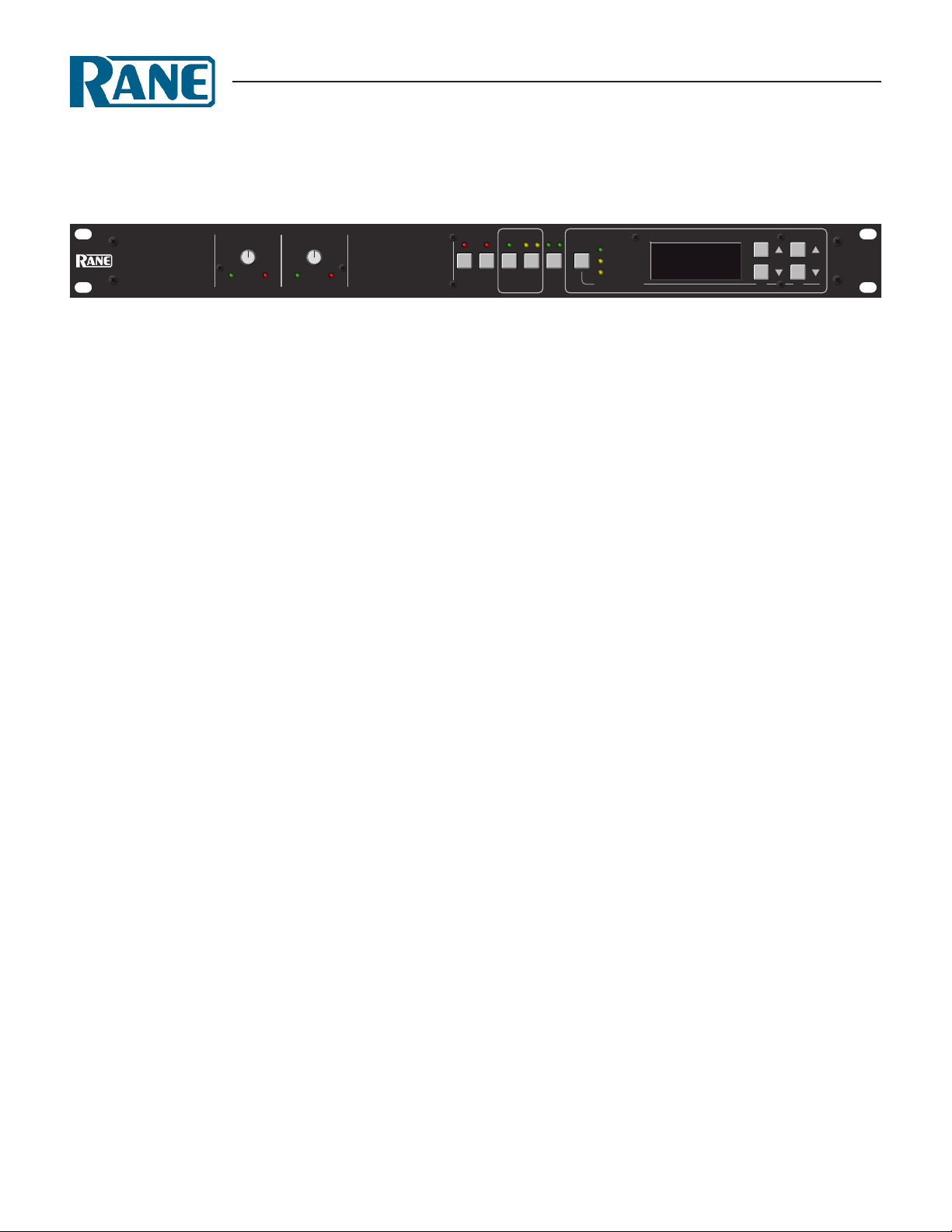
General Description
e Rane AD 22d is a fully balanced two Input, two Output
audio alignment Delay providing a range of 1.50 to 999.99 milliseconds on each Output. e Delay of each Output is independently adjustable in 10 microsecond and 1 millisecond increments. 24-bit audio converters provide excellent sound quality.
Each Output has two nonvolatile Memories (no batteries
required), A and B, for easy access to previously stored Delay
values. Remote Recall screw terminals on the rear accept external
configuration switches, permitting independent remote recall of
the Memories.
e AD 22d features XLR Inputs and Outputs, and is CE
certified for emissions. Housed in a single rack space, the unit
can operate as two independent channels (dual mono), or as a
stereo pair (edit both channels simultaneously).
Delay values can be displayed in milliseconds, feet or meters.
e ambient temperature of the room may be manually entered
in degrees Celsius or Fahrenheit. is temperature is used to accurately convert distance into time.
A recessed rear panel switch is available for locking out front
panel controls. In this mode, all of the front panel pushbuttons
are disabled with the exception of the Channel select and Dis-
AD 22d
AUDIO DELAY
play Mode buttons. e Channel button remains active so the
user may view the Delay values without risk of changing them,
and the Display Mode button allows displaying the Delay values
in milliseconds, feet or meters. Internal jumpers are available to
enable or disable Bypass while in Front Panel Lockout mode. e
default setting of these jumpers disables Bypass in Front Panel
Lockout mode.
Independent bypass relays provide a fail safe, hard-wired
bypass in case of power loss.
e AD 22d is a unity gain device with Sensitivity controls
to provide proper internal levels for the audio converters. If the
input signal is nominally +4 dBu, set the Sensitivity control fully
counter clockwise (+4 dBu). For those unable to touch a cable
and determine its signal level, Signal present and Clip indicators
provide visual acknowledgment that the Input signal is within
optimal range.
Powered from a low voltage UL listed and CSA certified
remote power supply (230 VAC supply meets LVD 73/23/EEC),
the AD 22d is exempt from safety agency requirements, and may
be used in any installation mandating agency compliance.
Features
• 1.50 to 999.99 ms Delay Range per Channel
• Two Independent Channels (2 In - 2 Out)
• Independent 10µs and 1ms Step Sizes
• Independent Remote Memory Recall
• Two EEPROM Memories per Channel (No Batteries)
• Front Panel Lockout Switch on Rear
• Delay Display in Milliseconds, Feet or Meters
• Fail-Safe Bypass for Each Channel
• Active Balanced XLR Inputs & Outputs
• UL/CSA/CE and 100/120/230 VAC Remote Power Supplies
Data Sheet-1

AD 22d
AUDIO DELAY
Features and Specifications
Parameter Specication Limit Units Conditions/Comments
Delay Range 1.50 to 999.99 1% msec
..........Increment Size 0.01 and 1.00 msec Independently controllable
..........Readout 5 digit LED
Propagation Delay 1.50 1% msec
Sampling Frequency 50k Hz
Data Conversion 24 bit
Input & Output Connectors XLR
Inputs: Type Active balanced
..........Impedance 25k 1% Ω balanced
..........Headroom 16 above Sensitivity setting 2 dB 20 Hz - 8 kHz
..........Max Level 20 dBu 1 kHz with Sensitivity at +4 dBu
Outputs: Type Active balanced cross-coupled
..........Impedance 200 1% Ω balanced
..........Max Level 20 (>2k ohm); 18 (>600 ohm) dBu 1 kHz with Sensitivity at +4 dBu
Overall System Gain 0 ±1 dB
Output Relays Yes Auto-bypass with power loss
LED resholds: Clip 4 before converter overload 1 dB 1 kHz
..........Signal Present -34 below Clip LED 1 dB 1 kHz
Frequency Response 20 Hz - 22 kHz +0/-0.5 dB +4 dBu, Sens@+4
THD + Noise 0.05 .01 % +4 dBu, Sens@+4, 20-20k, 30k Hz BW
Signal-to-Noise Ratio 85 2 dB +4 dBu, Sens@+4, 20 Hz - 20 kHz
Dynamic Range 101 2 dB +4 dBu, Sens@+4, 20-20k, A-weighted
Crosstalk >90 dB 20-20 kHz, +4 dBu, Sens @ +4 dBu
Unit: Agency Listing
..........120 VAC model Class 2 Equipment National Electrical Code
UL & CSA Exempt Class 2 equipment
..........230 VAC model Certified FCC Part 15J Class B Device
Power Supply: Agency Listing
..........120 VAC model UL File no. E88261
CSA File no. LR58948
..........230 VAC model CE-EMC EMC directive 89/336/EEC
CE-Safety LV directive 73/23/EEC
Power Supply Requirement 18 VAC w/center tap 0.1 Vrms Rane RS 1
..........Maximum Current 650 mA RMS current from remote supply
Unit: Construction All Steel
..........Size 1.75"H x 19"W x 8.5"D (1U) (4.4 cm x 48.3 cm x 21.6 cm)
..........Weight 6 lb (w/o power supply) (2.7 kg)
Shipping: Size 4.25" x 20.3" x 13.75" (11 cm x 52 cm x 35 cm)
.........Weight 10 lb (4.5 kg)
Note: 0 dBu=0.775 Vrms
Data Sheet-2

AD 22d Block Diagram
CH 1
CH 2
GND
REMOTE
DSP
LOCKOUT
PROM
AND
EEPROM
MEMORYPANEL
DELAYFRONT
CONTROLS
A/D D/A
RFI
0dB
FILTER
+
-
12dB
SIGNAL / CLIP
SENSE
CLIPSIGNAL
SENSITIVITY
3
2
1
INPUT
Channel 1 Shown, Channel 2 Identical
+
-
12dB
+
-
0 dB
BYPASS
BYPASS
RELAY
3
1
2
OUTPUT
Application Information
SENSITIVITY
To ensure optimal performance, adjust the Sensitivity control
so its indicator points to the nominal input signal level. Signal
present and Clip indicators provide verification that the signal is
within the optimal range. e Sensitivity control adjusts the input and output signal so that the AD 22d is always at unity gain.
SETTING DELAY
ere are two modes for setting Delay in the AD 22d: setting
one channel at a time and setting both channels simultaneously.
To set a single channel’s Delay, press the Channel button until
the LEDs indicate the Channel you want to set (1 or 2). en
press the up/down buttons until the display shows the desired
Delay. When editing both channels simultaneously (both Channel 1 and 2 LEDs on), the display shows the smaller of the two
current Delay values. In this mode, the two current Delay values
are “locked” together. Adjusting the up/down buttons changes
both values by the same relative amount. e edit both mode
allows easy stereo editing and also allows both drivers of a prealigned cluster to be moved forward or backward simultaneously.
STORING DELAY
Press the Store button. is stores both current Delay values into each channel's current Memory. A channel's current
Memory is indicated by the Memory LED lit when editing that
channel. e Store LED stops flashing when the current Delay
values match the stored values.
RECALLING DELAY
(A then B then A…) for the selected channel(s) only.
Pressing the Recall button alternately recalls stored Memories
SETTING TEMPERATURE
Hold down Display Mode and press the up/down buttons to
edit the AD 22d’s temperature setting. e 1 ms/Coarse buttons
display temperature in degrees Celsius, the 10µsec/Fine buttons
display degrees in Fahrenheit. No matter which unit (°C or °F),
adjustments are always in 1°C steps (or 1.8°F). e AD 22d does
not change the current Delay times for different temperature settings; only the displayed distance values are altered. (See example
below.)
REMOTE RECALL
A switch wired to the Remote Recall terminals allows remote
recall of stored Memories for each channel. Wire directly to a
room divider latch to automatically recall the two room configurations. Or store one Memory with the speaker stack’s distance
at one temperature and store the other Memory with the stack’s
distance at another temperature. en, during the warmer part
of the day, restore the warmer temperature.
For example, set up the initial temperature for 71.6°F (the
default), and set the stack’s distance for 250.00 feet. Press Store
to save this value in Memory A (250.00 feet at 71.6°F is 220.85
msec). en change the temperature setting to 100°F, and we’re
in Arizona. Notice that the current distance changes to 257.11
feet, but the current Delay time is still 220.85 msec. Now, edit the
current value for 250.00 feet (still your stack’s distance). Press
Store to save this value in Memory B (250.00 feet at 100°F is
214.74 msec.) Now Memory A has the proper value for the stack
at 71.6°F (220.85 msec/250 ft.), and Memory B has the value for
100°F (214.74 msec/250 ft.).
Data Sheet-3

AD 22d
OPEN
MEM A
CLOSED
MEM B
HARMFUL INTERFERENCE, AND (2) THIS DEVICE MUST
ACCEPT ANY INTERFERENCE THAT MAY CAUSE
RULES. OPERATION IS SUBJECT TO THE FOLLOWING
TWO CONDITIONS: (1) THIS DEVICE MAY NOT CAUSE
THIS DEVICE COMPLIES WITH PART 15 OF THE FCC
UNDESIRED OPERATION.
CLASS 2 EQUIPMENT
650mA
POWER
REMOTE RECALL PORT:
5 VOLT SOURCES 0.5 mA
CMOS SCHMITT TRIGGER INPUTS
REMOTE RECALL
CH1 CH2 GND
CHASSIS GND
BALANCED WIRING:
PIN 1
PIN 3 NEGATIVE
PIN 2 POSITIVE
RANE CORP.
MADE IN U.S.A.
AD 22d
ACN 001 345 482
CH 1 IN
CH 1 OUTCH 2 OUT CH 2 IN
CH 1 OUTCH 2 OUT CH 2 IN
CH 1 IN
AUDIO DELAY
Rear Panel
Architectural Specifications
e digital audio delay unit shall be a single rack space, two
input, two output configuration. e delay adjustment range
shall be from 1.50 to 999.99 ms, adjustable via increment/decrement pushbuttons, in both 10 microsecond and 1 millisecond
intervals. Independent remote recall terminals shall be provided
for external recall of stored configuration memories, two per
channel. A five (5) digit LED display shall indicate delay values
in milliseconds, feet or meters as well as temperature setting and
software revision level. Bypass status, current memory, channel,
and display modes shall be indicated with individual indicators.
A recessed rear-panel switch shall disable the front panel, yet
still allow viewing of delay values.
Independent input-output sensitivity controls shall be
included to allow calibration of the input signal for maximum
performance. e inputs and outputs shall be active balanced
with XLR connectors. Each channel shall have indicators for
signal present and input/output clip conditions.
e unit shall provide independent, fail-safe bypass relays
requiring no power to engage. RFI filters shall also be provided.
e unit shall have certified compliance with FCC docket
20780 Part 15J for Class B computing devices. e AD 22d shall
comply with EMCD 89/336/EEC (CE approved). e 120 VAC
model shall be powered from a UL listed, CSA certified remote
power supply, and the 230 VAC model shall be powered from
a remote power supply meeting LVD 73/23/EEC and EMCD
89/336/EEC standards. e unit shall be constructed entirely
from cold-rolled steel.
e unit shall be a Rane Corporation AD 22d.
References
1. Shaw, N. “Digital Delays, Parts One, Two & ree,” Sound & Communications, vol. 39, nos. 3, 5 & 10, (March, May, & October 1993).
2. Bohn, D. “Environmental Effects on the Speed of Sound,”J. Audio Eng. Soc., vol. 36, pp. 223-231 (April 1988).
©Rane Corporation 10 802 47th Ave. W., Muki lteo WA 982 75-50 98 T EL 425-355-6 000 FAX 425-347-775 7 WEB www.rane.com
Data Sheet-4
All features & specifications subject to change without notice. DOC 103488
 Loading...