

Page 1
Page 2
Page 3

1. WARRANTY EXPLANATION — PLEASE READ CAREFULLY
Rane offers a limited warranty, described in full on the Limited Warranty card included in the
packing materials, which covers both parts and labor necessary to repair any defects in the
manufacturing of your Rane product.
The warranty period is two (2) years, starting from either(i) the date of retail purchase, as noted
on either the sales slip from an authorized Rane dealer or on the warranty registration card sent,
in to the factory or, (ii) in the event no proof of purchase date is available, from the date of
manufacture, which is coded on the rear of the chassis.
If you send in the registration card according to the instructions on the card, or retain your sales
slip as proof of purchase, you will receive a full two (2) year warranty period from the date of
purchase, regardless of the date of manufacture. If you do not send in the registration card (“I
forgot.”), or you do not have a sales s1ip from an authorized Rane dealer (“My dog ate it.”), the
warranty period will only extend two (2) years from the date of manufacture.
All registered warranties are tracked by serial number, not by owner. Once your Rane product
is registered, it will be covered the full two years, regardless of any change in ownership.
Should you encounter any problems with your Rane product, be sure to contact either your
local Rane dealer or the Rane factory before taking it anywhere for repairs. We will help you to
identify and locate any specific malfunctions, possibly avoid needless shipment, or instruct
you as to the speediest method for authorized repair.
If you must send your Rane product to the factory or a warranty station for repair, BE SURE TO
INCLUDE THE FOLLOWING INFORMATION:
1. YOUR COMPLETE NAME AND RETURN SHIPPING ADDRESS (P.O.
box numbers are NOT acceptable)
2. THE SERIAL NUMBER OF THE RANE PRODUCT IN FOR REPAIR
3. A COMPLETE DESCRIPTION OF ANY AND ALL PROBLEMS YOU
ARE EXPERIENCING WITH THE PRODUCT.
Never ship the unit in any shipping carton other than the original or a replacement supplied by
Rane. Ship only by a reputable carrier. Be sure to insure the package for the full replacement
value. Rane cannot be held responsible for any damage incurred during shipping.
NOTICE REGARDING DAMAGES
THE RANE LIMITED WARRANTY COVERS ONLY THE COSTS IN LABOR AND MATERIALS TO
REPAIR DEFECTS IN MATERIAL OR WORKMANSHIP OR, AT RANE’S OPTION, TO REPLACE
DEFECTIVE PRODUCTS. CONSEQUENTIAL AND INCIDENTAL DAMAGES SUCH AS ECO-
NOMIC LOSS OR INJURY TO PERSON OR PROPERTY, WHATEVER THE CAUSE, ARE
EXCLUDED FROM COVERAGE. PLEASE REFER TO THE LIMITED WARRANTY CARD FOR A
FULL DESCRIPTION OF THE LIMITS ON THE COVERAGE OF THE LIMITED WARRANTY.
If you need further assistance concerning the repair, installation or operation of your Rane
product, please feel free to contact Rane galactic headquarters at:
Rane Corporation
10802 47th Avenue West
Mukilteo, WA 98275-5098
Phone: (425) 355-6000
FAX: (425) 347-7757
2
Page 4
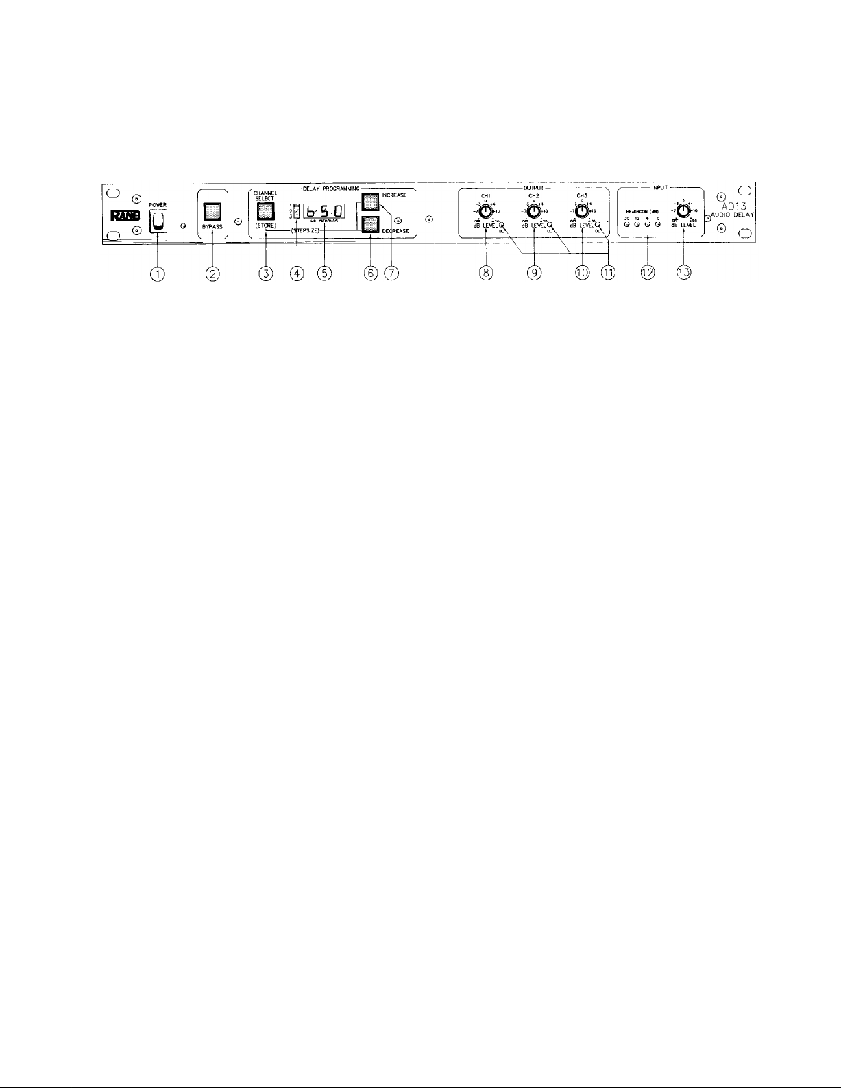
II. FRONT PANEL DESCRIPTION
1. POWER SWITCH: Pressing the top half of this switch will cause the mechanism contained
within to connect power to the circuitry of the unit causing it to operate (ON). Pressing the
bottom half will snap the switch into the opposite operating mode (OFF).
2. BYPASS SWITCH: Pressing this momentary pushbutton toggles all of the outputs of the AD
13 between the active and bypass mode. Bypass is indicated on the LED display by an “OFF”
indication.
3. CHANNEL SELECT SWITCH: Pressing this momentary pushbutton advances the output
channel pointer by one increment which simultaneously displays the delay setting of the
selected channel on the LED display. THIS BUTTON ALSO CAUSESTHE DELAY SETTING OF
THE PREVIOUSLY SELECTED CHANNELTO BE STORED IN THE NON-VOLATILE MEMORY
OF THE AD 13.
4. OUTPUT CHANNEL POINTER: This LED pointer alerts the operator to the channel number
currently being displayed by the LED display.
5. LED DISPLAY: The primary purpose of this display is to inform the user as to the amount of
delay currently applied to any of the three outputs, these outputs being selected by the
channel select switch and pointed to by the LED channel pointer to its left. The display also
indicates overall bypass by an “OFF” indication and can be used to display the software
revision of the system while in the bypass mode by holding the channel select button down
and pressing the “DECREASE” switch.
6. DECREASE BUTTON: Pressing this button will decrease the amount of delay on the selected
channel. PRESSING THE CHANNEL SELECT BUTTON WHILE THE DECREASE BUTTON IS
HELD WILL TOGGLE BETWEEN THE 20 MICROSECOND DELAY STEPS AND 1 MILLISECOND DELAY STEPS.
7. INCREASE BUTTON: Pressing this button will increase the amount of delay on the selected
channel. Pressing the channel select button while the increase button is held will toggle
between 20 microsecond delay steps and 1 millisecond delay steps.
8. CHANNEL 1 OUTPUT LEVEL CONTROL: This rotary control varies the output level of
channel 1 from “off” at its full counterclockwise position to unity at its center detent “12:00”
position to +20 dB at its full clockwise position.
3
Page 5

9. CHANNEL 2 OUTPUT LEVEL CONTROL: See channel 1 output level control immediately
above.
10. CHANNEL 3 OUTPUT LEVEL CONTROL: See channel 1 output level control immediately
above the item immediately above.
11. OUTPUT OVERLOAD INDICATORS: These red LEDs illuminate exactly 4 dB below the
onset of clipping, should any of the respective output stages approach this sort of difficulty.
12. lNPUT HEADROOM INDICATOR: These four LEDs will illuminate at the appropriate times
to indicate whetherthere is 20dB, 12dB, 6dB or 0dB of headroom left at the input of the analog
to digital converter. (Note: the 0dB LED comes on 2dB before clipping.)
13. INPUT LEVEL CONTROL: This rotary control varies the input sensitivity of the unit from off
at the full CCW position to unity at its center ”12:OO” position to +6dB at its full CW position.
4
Page 6

III. REAR PANEL DESCRIPTION
1. 3-PIN INPUT CONNECTOR: This is a differential active balanced input, connected such that
pin 2 is HOT, pin 3 is RETURN, and pin 1 is signal ground, NOT SHIELD GROUND. Shield
ground should only be connected to the case of the connector.
2. BARRIER STRIP INPUT AND OUTPUT CONNECTOR: From left to right, the connections are
as follows: + input,
channel 2 “+” output, channel 2 “–” output, output signal ground, channel 3 “+” output and finally,
channel 3 “–” output.
3. ACTIVE/TRANSFORMER SELECT SWITCHES: Pressing any of these switches “IN” to their
locked position places the respective output stage into its transformer balanced mode.
Pressing the switch again to release it from its “IN” position causes the output to be placed
back into its active balanced output configuration.
– input, input signal ground, channel 1 “+” output, channel 1 “–” output,
4. 3-PIN OUTPUT CONNECTORS: These are differential active balanced outputs, Pin 1 is
connected to signal ground, Pin 2 is the positive “+” output and Pin 3 is the negative “–” output,
The case is considered Pin 4 and should be used for shield terminations.
5. LOCK-OUT SWITCH: Pressing this switch to its
“INCREASE”,”
preset programs. The “CHANNEL SELECT” button will still operate allowing anyone who
passes by to view the settings of all three of the delays.
DECREASE” and “BYPASS” buttons on the front panel from changing any of the
“IN” and locked position prevents the
Page 7

IV. DIGITAL AUDIO THEORY
Now that most folks even remotely associated with the production and reproduction of sound
own at least one digital audio device, be it a CD player, digital tape system, or any of several
effects devices, most are at least remotely familiar with the fundamental principles of digital
audio. In case the sermon has missed you somehow, here it is again.
Digital Audio is the process of converting a time-varying electrical representation of an audio
signal into a bunch of numbers. Once you have a bunch of numbers you can store them,
manipulate them, give some away as wedding presents and sell the rest. Wasn’t that simple?
All seriousness aside, it really is almost that simple. If you’ve ever seen an audio waveform play
in real time on an oscilloscope, you have probably thought that it looked impossibly complex.
It really isn’t. An electrical audio signal is only one voltage at any given instant, even if the
triggering circuit on your oscilloscope makes you think otherwise. The speed that the voltage
can change from one level to another is a function of the bandwidth of the system that is
carrying it, and for the purposes of audio that bandwidth usually has an upper limit of 20kHz or
thereabouts. When the upper limit of our interest is at 20kHz, we can assume that any changes
which happen to our voltage waveform at a rate faster than that supported by our system’s
bandwidth will be of no audio importance.
An analog (or audio) to digital converter takes a “sample” voltage at a rate which is at least
twice the upper frequency of interest (in this case at least at a 40kHz rate) and converts that
sample voltage into a digital number which represents that voltage. Having converted the
samples to numbers, all one must do to enjoy the results is reconvert the numbers intovoltages
at the same rate that the samples were originally taken. The stream of voltages thus achieved
will appear to be an exact replica of the original signal.
A SILLY EXAMPLE.
The process of encoding audio into a digital format is a bit like sitting down with a voltmeter, a
pencil (or three) and several pieces of paper. All you have to do now is apply the audio signal to
the voltmeter and write down the meter reading once every forty thousandth of a second. To
play back the your work, go find a variable power supply and set the output voltage to the
correct level at the same rate at which you wrote down the numbers and you have a digital
audio system with an organic central processing unit.
Don’t forget to keep that pencil sharp.
Now that a full understanding of digital audio has been assured, we can proceed with the nuts
and bolts description of the Rane AD 13.
6
Page 8

V. FUNCTIONAL DESCRIPTION
If you attempt to read this without first digesting the previous section covering digital audio
theory you should be ashamed. Page numbers are included for a reason . . . . it gives one a
certain sense of the order in which to read this manual.
So, you have read the previous page and you’re ready to continue. Use the block diagram as a
pictorial guide as we describe the signal path of the AD 13. It will help you a lot.
AD 13 BLOCK DIAGRAM
In the beginning, signal is applied at the input either through the 3-pin connector or the barrier
strip. Whether the input is balanced or not, it will first pass through the Radio Interference
Filter to strip it of local police matters and reruns of Falcon Crest. It will then be applied to the
differential amplifier which unbalances a balanced input and rejects common mode noise on
the input lines. For unbalanced inputs the differential input amp behaves like a piece of
ordinary zip cord.
The next stop on the tour is the input level control. From the input level control the signal is
passed to the input gain adjustment amplifier which preconditions the audio signal for
presentation to the nine pole elliptic anti-aliasing filter. The anti-aliasing filter prevents any
frequencies above 20kHz from entering the audio to digital converter. If they were allowed to
pass they would cause a great deal of difficulty with the meter reader and some severe
distortion at the output of the system.
The next stop in the signal path is the pre-emphasis block This circuit boosts high frequencies
relative to the tower frequencies for two reasons: First, high frequencies are usually lower in
level than low frequencies and can be processed with higher resolution when boosted and
second, to reduce the output sensitivity of the unit when de-emphasis is applied at the output
to compensate for the pre-emphasis and return the overall frequency response to flat. The
lower high frequency sensitivity at the output results in a lower output noise level.
7
Page 9

The branch in the road after the pre-emphasis leads to a dead end at the headroom meter,
which must be attached after the pre-emphasis is applied to the input signal so that a visual
indication of what is really being applied to the digital converter can be monitored. Up the
other fork lies the sample and hold circuit. This clever trick provides the converter with a
steady voltage during the conversion process. To do this, the sample and hold actually holds
the input voltage steady during each sample cycle, releasing the input only after a digital
reading is completed. Once the sample is complete, the sample and hold takes another look at
the input and then freezes the voltage at a new level.
The analog samples provided by the sample and hold then pass on to the input stage of the
analog to digital converter. Unlike the example which was required reading on the previous
page, the converter in the AD 13 runs at a 50kHz sample rate (just to be sure). It will then
produce a binary number in the range of 0 to 16,383 (no, this is not binary; binary would be “in
the range of 00000000000000 to 11111111111111”), at every 1/50,000 second interval.
At this point the signal path disappears into some murky pool casually labelled “Digital Signal
Processing” in the block diagram. It is into this mystical madness that the front panel control
switches are connected as well as the display, and the three digital to analog output
converters.
The memory which provides the delay is found in this block, along with the CPU (central
processing unit, or computer for short) and several housekeeping circuits which are necessary
to keep the lines from getting tangled at the 16,000,000 cycle speed of the CPU. AII of the data
coming into the block from the analog-to-digital converter is written to memory, and is made
available for recall at any 20 microsecond real time interval from 0 to 654 milliseconds after it
has been stored. All three of the digital to analog converters has access to the data at any time
within the boundaries of the maximum delay.
The front panel switches are connected to the CPU as is the display and the memory. Switch
closures tell the digital-to-analog converters where to look for the appropriate data to provide
the amount of delay indicated on the display. Leaving out all of the details is really quite
necessary. You see, we have a certain budget for the printing and handling of these owner’s
manuals and the amount of paper and ink it would take to go beyond these limits would be
prohibitive.
Data is clocked out of the digital processing block to the three digital to analog converters in an
appropriate manner to reconstruct a replica of the original analog input, plus time delay, if any.
The reconstructed audio is actually a series of steps identical to the steps which appeared at
the output of the sample and hold. At this point in the signal path lies the de-emphasis circuit
which removes the frequency shaping that was applied to the signal before conversion to the
digital domain. The aforementioned steps in the audio are then removed with another nine
pole elliptical filter. All of the frequency components of these steps are higher in frequency
than the cutoff frequency of the filter. At the output of the filters there is a buffer amplifier
which scales the gain appropriately and drives the output level control pot.
After this processing, the signal is subjected to a pair of amplifiers which either directly drives
the outputs in an active balanced or unbalanced fashion or through a switch selectable output
coupling transformer. The very last item of importance is the bypass relay. This relay must be
energized by the CPU for any delayed signal to be present at the output. During warm-up and
power off conditions the relay is in its resting position which diverts all input signals directly to
the output connectors.
8
Page 10

VI. SYSTEM CONNECTION
If you have already read the first two pages of this manual, the following will seem redundant. It
is, however, of the utmost importance that the user totally comprehend the interconnect
requirements of any piece of equipment. It is for this reason that the people at Rane don’t
mind saying this twice. It can never be said too often.
Failure to interconnect audio components properly is the number one leading cause of
problems and nasty noises. The rules are really very simple, and the following procedures will
work equally well in both balanced and unbalanced situations. The real advantage to
operating a system in the balanced mode is the lack of necessityto connect ground references
between two units. These ground connections only increase the risk of creating ground loops.
If the various components are properly connected to a pipe ground or a similar earth
connection through their 3rd pin in the line cord, intercomponent signal grounding is
unnecessary.
In the unbalanced mode, it becomes necessary to string the signal grounds between units.
When this is done, it is imperative that all shielding be done using chassis ground and not signal
ground. Even in the balanced mode, chassis ground should always be used for the purposes of
shielding to prevent loops.
For further information on this subject, obtain a copy of Rane Note 110 on the science of
system interconnect. It is really quite revealing.
Back to the AD 13 specifically, the 3-pin input and output connectors use the same wiring
configuration for all pins. Pin 2 is always the positive connection in Rane products (per IEC 258
and ANSI PH7.102-1983), pin 3 is inverted (negative) and pin 1 is signal ground. Be sure to
check out the units to which you are connecting the AD 13 since manufacturers seem to have
difficulty agreeing on the standard or even recognizingthat it exists. Some use 3 as hot and 2 as
negative, however there are no other versions of this scheme known to us. If the worst happens
and you cannot determine the pinout of an alien unit, the most that will happen is that the
signal will be inverted in the connection. This will not cause any problems, especially if no one
knows that it is inverted. Some will claim to be able to hear the difference, if they know that it
has occurred. (If you are connecting a stereo system ignore the preceding.)
Unbalanced operation simply requires that you tie pin 2 to the hot lead, pin 1 to the signal
ground lead and shield to case only. Be sure to leave pin 3 open on outputs and tie it to pin 1 on
inputs. Connecting it to ground or to pin 2 on the output connector will cause excessive
current to flow and disrupt signal fidelity. This will cause no damage to the AD 13, only to your
signal path.
When using the barrier strip, there can be little confusion as to the proper connection practice,
thanks to the clear legends printed above and below the connectors. Again, + to +, – to –, and
signal ground is not required unless unbalanced operation is required. If the latter is the case,
do not use signal ground for shielding. Use chassis ground only for connecting shields for
unbalanced operation.
Once the wiring is completed, one must make the choice between active or transformer
output operation. There are as many sides to this issue as there are to any other controversial
topic. We prefer to lean toward the school of common sense which dictates that if you have
unsolvable problems in one mode of operation which are solved by switching to the other,
then do so. If you have difficulties in neither mode, then let your personal preference guide
your actions. Wasn’t that easy?
Page 11

VII. OPERATING INSTRUCTIONS
INITIAL POWER-UP
Basic operational guidelines are straightforward. Once all circuit connections have been
properly accomplished the system should be ready to power up. It is usually recommended
that all signal processing be turned on before the amplifier is powered up to prevent
unnecessary surprises. It is also wise to start with all of the level controls in their full CCW or
“off” positions. This will further ensure that there are no unwanted glitches.
When the power switch on the AD 13 is turned on, the display will illuminate with the word
RANE and will stay in that condition for approximately 2 seconds. During this time the CPU
performs its self-test functions which guarantees that it will function when the unit switches to
its active mode.
CHANGING DELAY STEP SIZE
Once operation is achieved, the channel select indicator illuminates next to channel one and
the delay last programmed for channel one will be displayed. The INCREASE/DECREASE
switches will always affect the delay time by 20 microsecond intervals on power up. This may
be changed to the 1 millisecond step mode by pressing either INCREASE or DECREASE and
then tapping the CHANNEL SELECT pushbutton. Tapping it again will toggle back to the short
increment mode.
SETTING TIME DELAYS
Setting up the time delays for optimum effectiveness in the AD 13 or any other delay device
can be something of an art. For normal situations, you can estimate or measure the distance
between speakers and get a reasonably good correlation between distance and milliseconds
on a one to one basis. For example, an auditorium with primary speakers or cluster at the front
of the hall and auxiliary reinforcement 40 feet to the rear would require approximately 40
milliseconds of delay on the rear speakers for maximum intelligibility. Some experimentation
will be required depending on the altitude of the installation and the weather on the day the
alignment is performed. (Yes, the speed of sound does change with temperature and
humidity, although not usually by a large enough degree to warrant your concern unless you
are aligning down to the quarter inch.)
For clarity, it’s a good idea to put the shortest delay on channel one, the next on channel two,
and so forth. It is by no means necessary, just easier to keep track of.
STORING DELAY SETTINGS
Writing a delay setting to non-volatile memory requires that the channel select be cycled
through its three positions. In otherwords, if you were to power up the unit into its channel one
select mode, set the channel one delay time, do nothing else and turn off the unit, the delay
setting would be lost. Cycling the channel select through its one-two-three-one sequence
would write all three indicated delay settings to memory.
10
Page 12

SETTING LEVELS
Whether or not you have set the desired delays, you may, at any time, increase the input
control to a comfortable level and any or all of the output controls. Since the AD 13 is normally
going to function at the input of the amplifier, there should rarely be any need for anything but
unity gain at either the input or the outputs. Always remember to take all the gain you will ever
need right at the very input of a sound system, and not here and there down the chain. No
matter what sort of mixer, processor or amplifier you are using, gain at the front end will yield
the lowest overall noise.
With most power amplifiers you should find that with the input and output level controls set
for unity gain on the AD 13, the power amps will clip a bit before the 0dB headroom LED
illuminates on the input headroom meter. If this is not the case, back down the input control. It
is always desirable to have an amplifier clip before a digital processor gets into trouble. Fact of
life number 425: Amps clip cleaner than digital devices. Set the input level control so music
peaks just barely tickle the 0dB LED.
11
Page 13

VIII. SPECIFICATIONS
TIME DELAY
Range: 0 to 655ms
Increment Size: 20µs or 1 ms throughout entire range
Readout: 3 digit LED with autoranging decimal point. Accuracy: ±5%
DATA CONVERTERS
Conversion Rate: 50kHz oversampling
Type: Linear pulse code modulation (PCM). (Philips CD data converters).
Quantity: 4 (1 A/D, 3 D/A)
ANTI-ALIASING & SMOOTHING FILTERS
Type: 9th-order elliptic
Features: Linear Group Delay
Quantity: 4 (1 input, 3 output)
FREQUENCY RESPONSE: 20-20 kHz, ±1 dB
DYNAMIC RANGE (ratio of maximum output level to the noise floor): 90dB min (20kHz
bandwidth, any delay setting)
SIGNAL-TO-NOISE RATIO: 84dB minimum below +4dBu,
(20kHz noise bandwidth, unity gain)
THD + NOISE: less than 0.l%, 20-20kHz @ +4dBu, unity gain
INTERMODULATION DISTORTION (SMPTE): less than 0.1% @ +4dBu
RESIDUAL PROPAGATION DELAY: 190µs.
EMI/RFI EMISSION LEVELS: Certified compliance with FCC docket 20780 Part 151 for Class A
computing devices; also satisfies VDE0871 for Class A computing
devices
INPUT SPECIFICATIONS
Input Impedance: 10k ohms
Maximum Input Level: +22dBu
Input Gain Range: Off to +6dB
OUTPUT SPECIFICATIONS:
Output Impedance: 600 ohms balanced; 300 ohms unbalanced
Maximum Output Level: +26dBu
Output Gain Range: Off to +20dB
Overload LED Threshold: 4dB below clipping
MAXIMUM POWER CONSUMPTION: 30 Watts
DIMENSIONS:
1.75”H x 19”W x 8.5” rack depth
All steel chassis & front panel
WEIGHT: 8 Ib net
Note: 0dBu = 0.775Vrms
All specifications subject to change without notice, hopefully for the better.
12
 Loading...