

Rane AC 23 User Manual

OPERATORS MANUAL
AC 23
ACTIVE CROSSOVER
QUICK START
This is an automatic crossover! By automatic, we mean that the AC 23 is smart enough to know whether you want to
run it as a two channel crossover, or as a single channel unit. It knows by the way the plugs are inserted how your system is
to be configured. However, just because it is automatic, doesn’t mean that it will not automatically confuse you when you
try to connect it in a bench test situation. Note: Labels above the controls refer to the unit being operated in the 2- or 3-
Way Stereo mode. Labels below the controls refer to the unit being operated in the 4- or 5-Way Mono mode.
Plugging a signal into the CHANNEL 1 INPUT and nothing into the CHANNEL 2 INPUT tells the unit that you are
running a single channel system in Mono 4- or 5-Way mode, and therefore sets the unit up to be a single channel device.
This can lead one to think that there are some dead channels in the unit when looking for output in places where there
shouldn’t be any. The even more automatically confusing part is the way that the Output connectors decide whether the unit
is a 4-Way or 5-Way crossover. It is actually rather straightforward.
To test the unit as a Mono 4-Way, first slide the CHANNEL 1 and 2 switches on the back to 3-WAY. Connect the
INPUT source to CHANNEL 1 only. Following the labels below the jacks, look at SUB OUT, then look at LOW OUT,
now go back to MID OUT, and then proceed to the HIGH OUT. So far, so good.
To test the AC 23 as a Mono 5-Way, the only precaution required is there must be a “dummy” plug (¼" unconnected
plug) inserted into the HI MID OUT to program the crossover properly. When you reach the point where you want to
measure the output of the channel with the dummy in it, simply remove it and insert your test output plug in that location.
When operating the AC 23 as a Stereo 3-Way, follow the diagram on page Manual-5, reading the labels above the jacks
and controls. To drive both Channels with a mono signal, connect only to the CHANNEL 2 INPUT. This approach is the
same as if you used a wye cable to both Inputs.
The AC 23B is available as a fully balanced output version equipped with XLR connectors (for inputs and outputs)
instead of the ¼" jacks. If you are connecting to balanced amplifiers from the AC 23 or are running crossover output cable
lengths greater than 10 feet (or 3 meters), we highly recommmend you purchase an AC 23B.
Never connect anything except an RS 1 or other approved Rane AC power supply to the thing that looks like a
telephone jack on the rear. This is an 18 VAC center-tapped power unit. Consult the Rane factory for replacement or
substitution.
AC 23 CONNECTION
Balanced/Unbalanced Inputs
The ¼" Input jacks on the AC 23 are TRS (tip-ringsleeve). We recommend connecting the AC 23 with a balanced cable from the balanced output of a mixer or equalizer.
If a balanced output is not available, and the cable run is
less than ten feet (three meters), inserting an unbalanced ¼"
TS (tip-sleeve) plug works in most situations.
WEAR PARTS: This product contains no wear parts.
Unbalanced Outputs
The ¼" Output jacks on the AC 23 are unbalanced TS
(tip-sleeve). We recommend that cables to the amplifiers be
no longer than ten feet (three meters).
See the “Sound System Interconnection” RaneNote
included with this manual for more information on cabling
and grounding requirements.
Manual-1
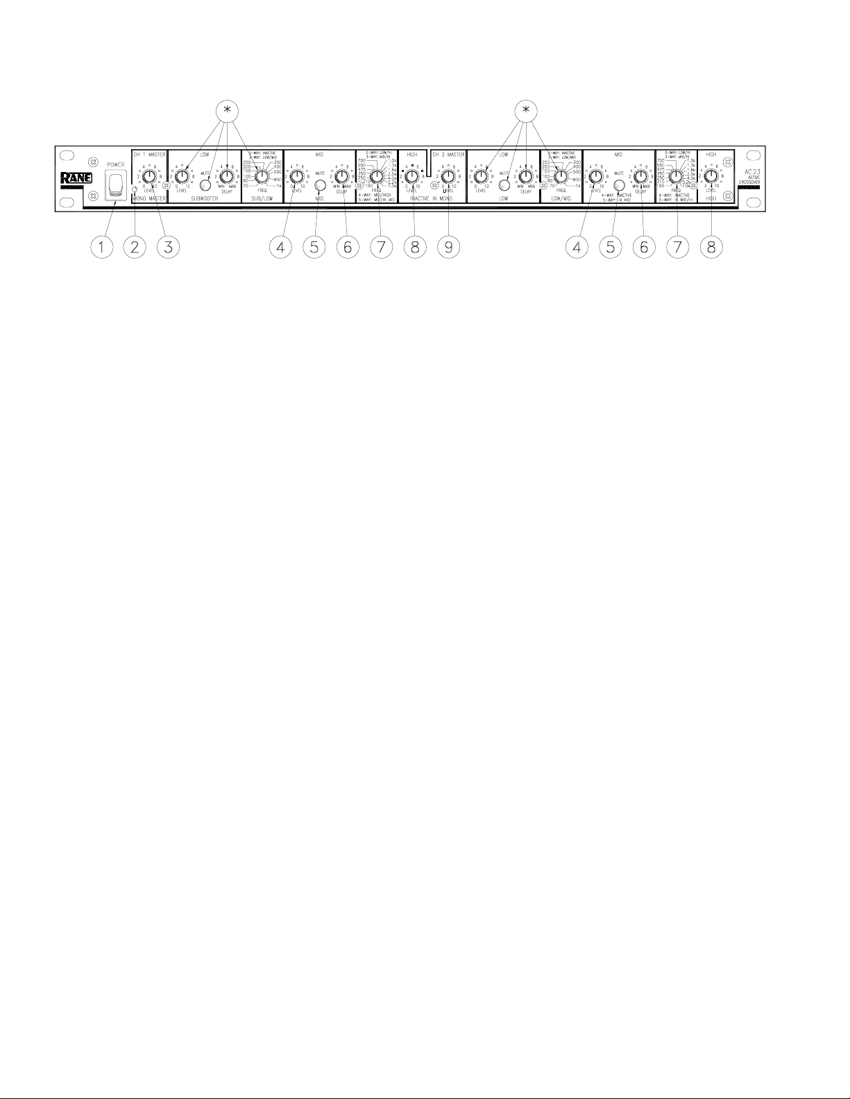
FRONT PANEL: STEREO 2-WAY CONFIGURATION
Observe the labels screened above the controls for stereo operation.
NOTE: In the 2-Way mode, the AC 23 crossover range is from 190 Hz to 7 kHz. The model AC 22 crossover in
stereo 2-Way mode is recommended when the crossover point needs to be outside of this range.
* Not used in 2-Channel 2-Way Mode
햲 POWER switch: Two guesses.
햳 POWER indicator: When this yellow LED is lit the unit is ready to operate.
햴 CHANNEL 1 MASTER LEVEL control: Sets the overall Level of Channel 1 without altering the relative settings of the
Low and High frequency Outputs. Unity gain for all level controls is at “7”.
햵 LOW LEVEL control: Sets the Level of signal going to the Low Frequency output in this channel. Refer to ‘Setting the
Output Level Controls’ on page Manual-15.
햶 LOW MUTE switch: When pressed to the in position, all signal is removed from the Low Frequency Output. This eases
tune-up procedures as described on pages Manual-11-16.
햷 LOW DELAY control: Adds from 0 to 2 ms of time Delay to the Low Frequency Output only. This allows a low fre-
quency driver to be electronically phase-aligned with a mid frequency driver whose diaphragm is situated behind the low
frequency diaphragm. Refer to ‘Time Delay Adjustment Procedure’ on page Manual-10.
햸 LOW/HIGH crossover frequency selector: This 41-detent selector sets the crossover frequency between the Low and
High frequency Outputs. Refer to ‘Selecting Crossover Frequencies’ on page Manual-10.
햹 HIGH LEVEL control: Sets the Level of signal going to the High frequency Output only.
햺 CHANNEL 2 MASTER LEVEL control: Sets the overall Level of Channel 2 without altering the relative settings of the
Low and High Outputs.
Manual-2
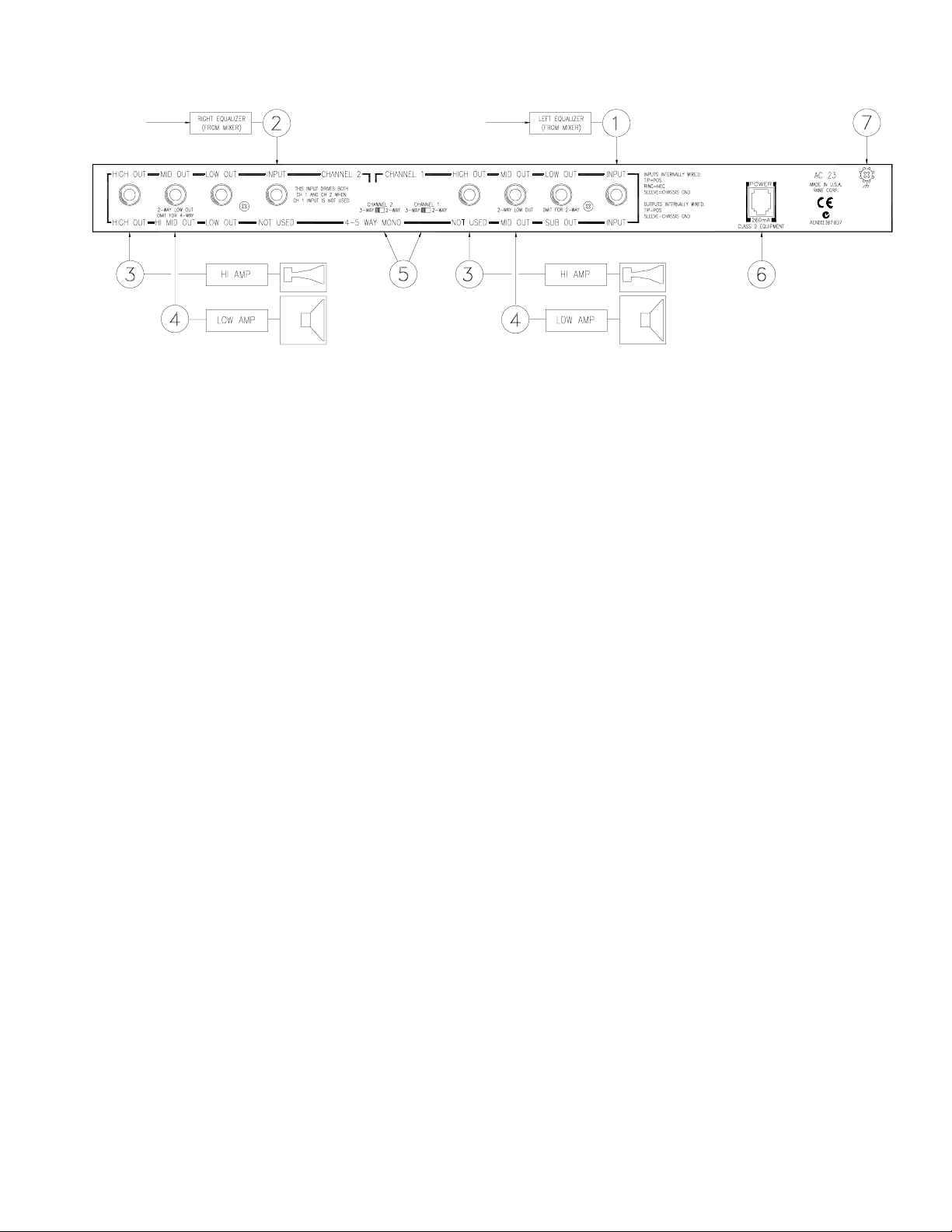
REAR PANEL: STEREO 2-WAY INSTALLATION
Observe the labels above the Inputs and Outputs for Stereo operation.
햲 CHANNEL 1 INPUT: These ¼" Inputs accept either balanced TRS (tip-ring-sleeve) or unbalanced TS (tip-sleeve) plugs.
Connect the output of the mixer, equalizer or other signal source to this input. Note: Use this input only if you are running
two separate channels from the mixer or other source. Connect this input to the left channel output of the mixer, equalizer or
other signal source. If you are running two speaker systems from a single mono signal, omit this input and use only the
CHANNEL 2 INPUT. See #2 below.
햳 CHANNEL 2 INPUT: For true stereo operation, connect this Input to the right channel output of the mixer, equalizer or
other signal source. NOTE: Two separate speaker systems may be independently operated from a single mono source by
using only the CHANNEL 2 INPUT and omitting the Channel 1 Input. As long as nothing is plugged into the Channel 1
Input, CHANNEL 2 will drive BOTH Channels of the AC 23 internally.
햴 HIGH FREQUENCY OUTPUTS: These are ¼" TS (tip-sleeve) unbalanced Output jacks. Connect the CHANNEL 1
HIGH OUT to the left channel input of the high frequency amplifier, and the CHANNEL 2 HIGH OUT to the right channel
input of the high frequency amp.
햵 MID FREQUENCY OUTPUT: Connect the CHANNEL 1 MID OUT to the left channel of the mid frequency amplifier,
and the CHANNEL 2 MID OUT to the right channel of the mid amplifier.
햶 2-WAY/3-WAY SWITCH: Converts the outputs from Stereo 3-Way to Stereo 2-Way. Be sure to slide the switches to the
2-WAY position.
햷 POWER input connector: Use only a model RS 1, or other remote AC power supply approved by Rane. This unit is
supplied with a remote power supply suitable for connection to this input jack. This is an 18 VAC center tapped power
supply. Contact Rane for a replacement or substitution.
햸 Chassis ground point: A #6-32 screw is used for chassis grounding purposes. Always connect crossover chassis ground to
amplifier chassis ground. See the CHASSIS GROUNDING note on page Manual-7 for details.
Manual-3
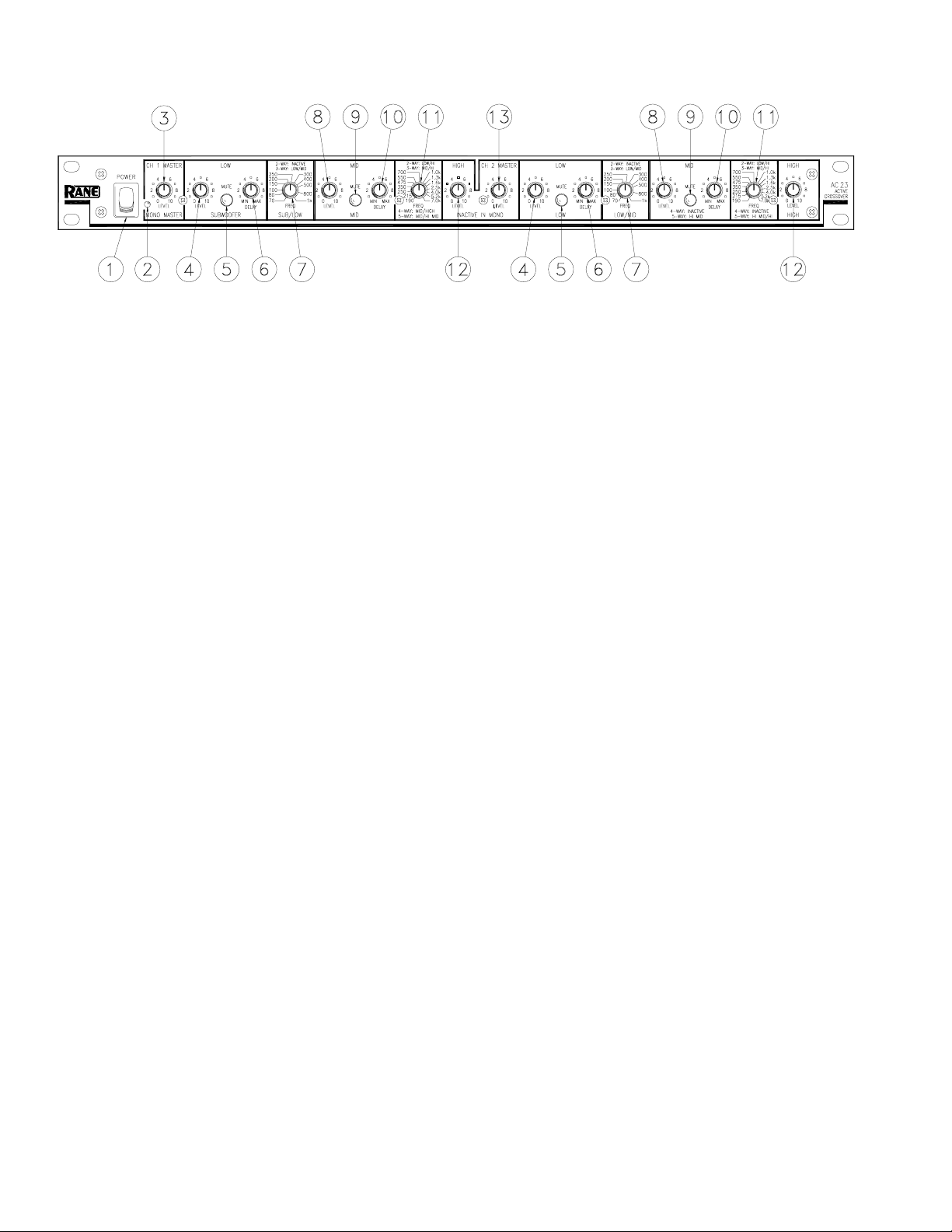
FRONT PANEL: STEREO 3-WAY CONFIGURATION
Observe the labels screened above the controls for stereo operation.
햲 POWER switch: Two guesses.
햳 POWER indicator: When this yellow LED is lit, the unit is ready to operate.
햴 CHANNEL 1 MASTER LEVEL control: Sets the overall Level of Channel 1 without altering the relative settings of the
Low/Mid/High frequency Outputs. Unity gain for all Level controls is at “7”.
햵 LOW FREQUENCY LEVEL control: Sets the Level of signal going to the Low frequency Output only in this Channel.
Refer to page Manual-15 for guidance with the Level control settings.
햶 LOW MUTE switch: When pressed to the in position, all signal is removed from the Low frequency Output. This eases
tune-up procedures as described on pages Manual-11-16.
햷 LOW DELAY control: Adds from 0 to 2 ms of time delay to the Low Frequency Output only. This allows a low frequency
driver to be electronically phase-aligned with a mid frequency driver whose diaphragm is situated behind the low frequency
diaphragm. Refer to page Manual-10.
햸 LOW/MID crossover frequecny selector: This 41-detent selector sets the crossover frequency between the Low and Mid
Outputs. Refer to page Manual-10.
햹 MID LEVEL control: Sets the Level of signal going to the Mid Output in this Channel only.
햺 MID MUTE switch: Removes all signal from the Mid Frequency Output when pressed to the in position.
햻 MID DELAY control: Adds from 0 to 2 ms of time Delay to the Mid Output only.
햽 MID/HIGH crossover frequency selector: Sets the crossover frequency between the Mid and High Outputs in this
Channel.
햾 HIGH LEVEL control: Sets the Level of signal going to the High Output only.
햿 CHANNEL 2 MASTER LEVEL control: Sets the overall Level of Channel 2 without altering the relative settings of the
Low/Mid/High Outputs.
Manual-4
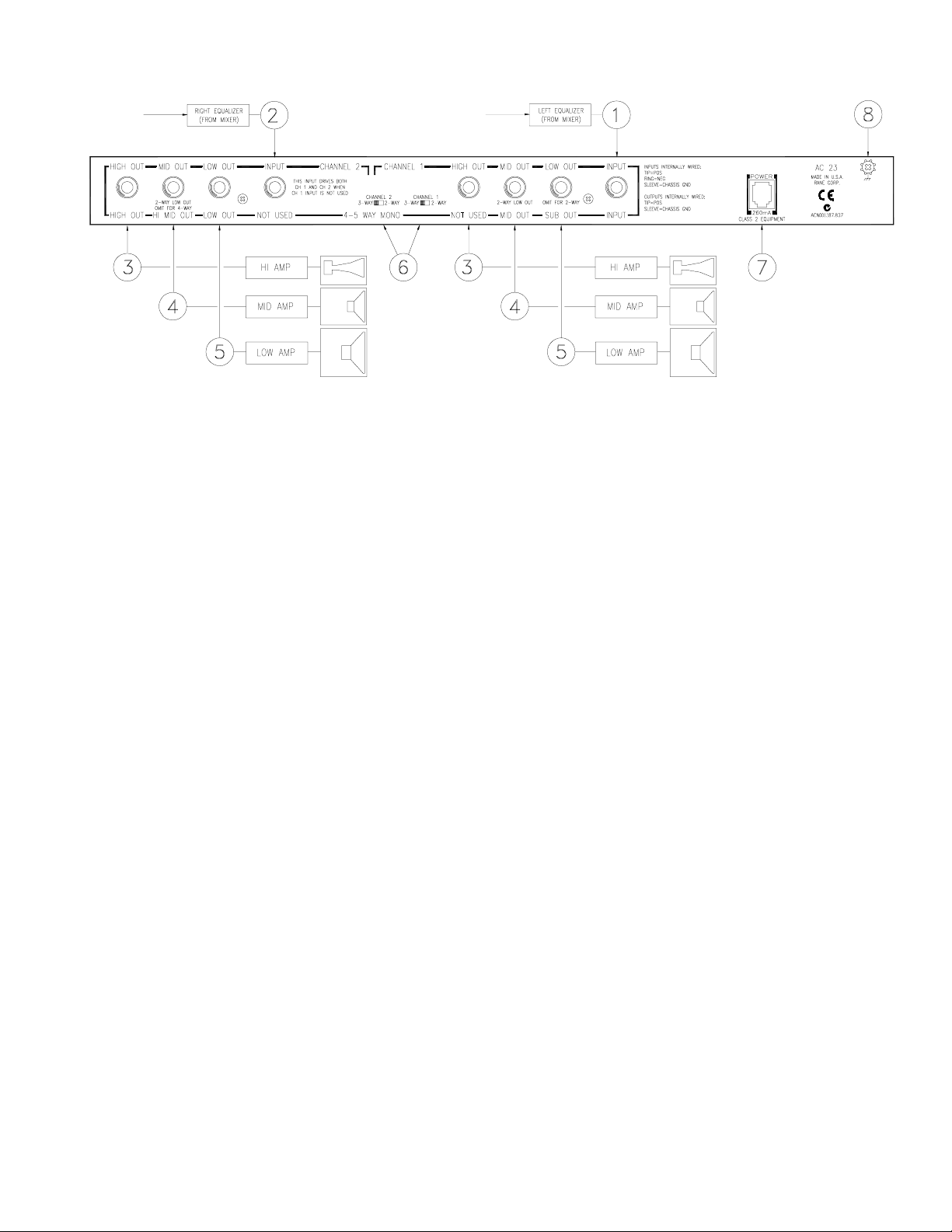
REAR PANEL: STEREO 3-WAY INSTALLATION
Observe the labels above the Inputs and Outputs for Stereo operation.
햲 CHANNEL 1 INPUT: These ¼" Inputs accept either balanced TRS (tip-ring-sleeve) or unbalanced TS (tip-sleeve) plugs.
Connect the output of the mixer, equalizer or other signal source to this Input. Note: Use this input only if you are running
two separate channels from the mixer or other source. Connect this Input to the left channel output of the mixer, equalizer or
other signal source. If you are running two speaker systems from a single mono signal, omit this Input and use only the
CHANNEL 2 INPUT. See #2 below.
햳 CHANNEL 2 INPUT: For true stereo operation, connect this Input to the right channel output of the mixer, equalizer or
other signal source. NOTE: Two separate speaker systems may be independently operated from a single mono source by
using only the CHANNEL 2 INPUT and omitting the Channel 1 Input. As long as nothing is plugged into the Channel 1
Input, CHANNEL 2 will drive BOTH Channels of the AC 23 internally.
햴 HIGH FREQUENCY OUTPUTS: These are ¼" TS (tip-sleeve) unbalanced Output jacks. Connect the CHANNEL 1
HIGH OUT to the left channel input of the high frequency amplifier, and the CHANNEL 2 HIGH OUT to the right channel
input of the high frequency amp.
햵 MID FREQUENCY OUTPUT: Connect the CHANNEL 1 MID OUT to the left channel of the mid frequency amplifier,
and the CHANNEL 2 MID OUT to the right channel of the mid amplifier.
햶 LOW FREQUENCY OUTPUTS: Connect the CHANNEL 1 and 2 LOW OUTS to the left and right channels of the low
frequency amplifier, respectively.
햷 2-WAY/3-WAY SWITCHES: Converts the Outputs from Stereo 3-Way to Stereo 2-Way. Be sure the switches are in the
3-WAY position.
햸 Power input connector: Use only a model RS 1 or other power supply approved by Rane. This unit is supplied with an 18
VAC center tapped remote power supply suitable for connection to this input jack. Consult the factory for a replacement or
subsitution.
햹 Chassis ground point: A #6-32 screw is used for chassis grounding purposes. Always connect the crossover chassis to the
amplifier chassis. See CHASSIS GROUNDING note on page Manual-7 for details.
Manual-5

FRONT PANEL: MONO 4-WAY AND 5-WAY CONFIGURATION
Observe the labels screened below the controls for mono operation.
햲 POWER switch: Two guesses.
햳 POWER indicator: When this yellow LED is lit, the unit is ready to operate.
햴 MASTER LEVEL control: Sets the overall Level of the entire unit in Mono mode, without changing relative settings of
the individual Sub/Low/Mid/High Outputs. Unity gain for all Level controls is “7”.
햵 SUBWOOFER LEVEL control: Sets the Level of signal going to the Sub Output. See page Manual-15.
햶 SUBWOOFER MUTE switch: Removes all signal from the Sub Output when pressed to the in position. This eases the
system tune-up procedure, as described on pages Manual-11-16.
햷 SUBWOOFER DELAY control: In Subwoofer applications this control has virtually no effect and will normally be set to
minimum (MIN). Refer to page Manual-10.
햸 SUB/LOW crossover frequency selector: This 41-detent selector sets the crossover frequency between the Subwoofer and
Low Outputs. Refer to page Manual-10 to determine the proper setting for your system.
햹 LOW LEVEL control: Sets the Level going to the Low frequency Output.
햺 LOW MUTE switch: Removes all signal from the Low Output when pressed in.
햻 LOW DELAY control: Adds from 0 to 2 ms of time Delay to the Low Frequency Output only. Refer to page Manual-10
for alignment procedure.
햽 LOW/MID crossover frequency selector: Sets the crossover frequency between the Low and Mid frequency Outputs.
햾 MID LEVEL control: Sets the Level of signal going to the Mid Output only.
햿 MID MUTE switch: Removes all signal from the Mid Output when pressed in.
헀 MID DELAY control: Adds from 0 to 2 ms of time Delay to the Mid frequency Output only.
헁 MID/HI MID crossover frequency selector: Sets the crossover frequency between the Mid and Hi Mid Outputs.
* NOTE: Both the CHANNEL 1 HIGH LEVEL control and CHANNEL 2 MASTER LEVEL control are automatically bypassed
when the AC 23B is switched to "MONO" on the back panel. Adjusting these controls has no effect in the Mono mode.
Manual-6
 Loading...