

Page 1
Ramsey Winch Company
OWNER’S MANUAL
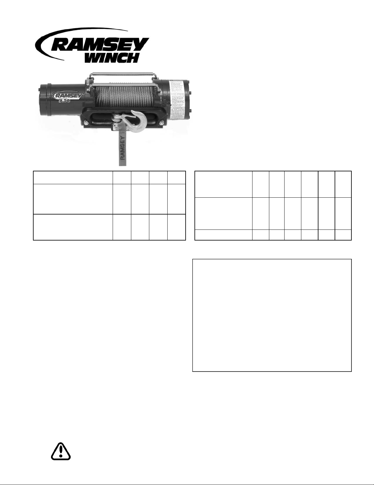
Model REP 9.5e
Front Mount Electric Winch
12 volt available
Layer of Cable 1 2 3 4
Rated Line Pull Per
Layer
Cumulative Cable
Capacity Per Layer
5/16" (8mm) dia. Cable
* Depends on cable being uniformly wound onto drum. Ramsey performance data is compiled from actual winch testing.
(lbs) 9,500 7,700 6,500 5,700
(kg) 4,310 3,490 2,950 2,590
(ft)* 15 35 60 95
(m)* 4 10 18 28
Congratulations
You have purchased the finest winch available in its service
class. The REP 9.5e winch features a highly efficient 3 stage
planetary gear set. It utilizes a series-wound D.C. motor. A
safe positive clutch allows free spooling for quick cable deployment. An automatic load-holding brake is designed to
hold the full rated capacity of the winch.
This winch was designed and manufactured to provide you
with the utmost in utility. As with any device that combines
power and movement in its use, there are dangers if improperly used. At the same time, there are easier and faster ways
for getting the job done if certain precautions are taken first.
Please read this manual carefully. It contains useful ideas in
obtaining the most efficient operation from your Ramsey
Winch and safety procedures you need to know before beginning use. When you follow our guidelines for operation,
your Ramsey Winch will give you many years of satisfying
service. Thank you for choosing Ramsey. You will be glad
you have one working for you.
First Layer
Line Pull
Line Speed
First Layer
Amp Draw 12V 99 170 250 315 370 420
(lbs) NO 2,000 4,000 6,000 8,000 9,500
(kg) LOAD 900 1,810 2,720 3,620 4,310
(FPM) 20 16 11 7 5 3
(MPM) 9.1 4.8 3.3 2.1 1.5 0.9
Contents
Safety Precautions......................................................2
Tips for Safe Operation ...............................................2
Techniques of Operation .............................................3
Installation.............................................................. 4-7
Electrical Connections & Operations............................5
Maintenance...............................................................8
Operating Instructions.................................................8
Trouble Shooting Guide...............................................9
Winch Parts List ................................................. 10-11
Warranty .....................................................Back Cover
Please Note: The Ramsey REP 9.5e winch is designed
for front mount vehicle use. It is not designed for and
should not be used in industrial applications (car haulers/carriers, wreckers, hoisting, etc.), and Ramsey
does not warrant it to be suitable for such use. Ramsey
makes a separate, complete line of winches for industrial/commercial use. Please contact the factory for
further information.
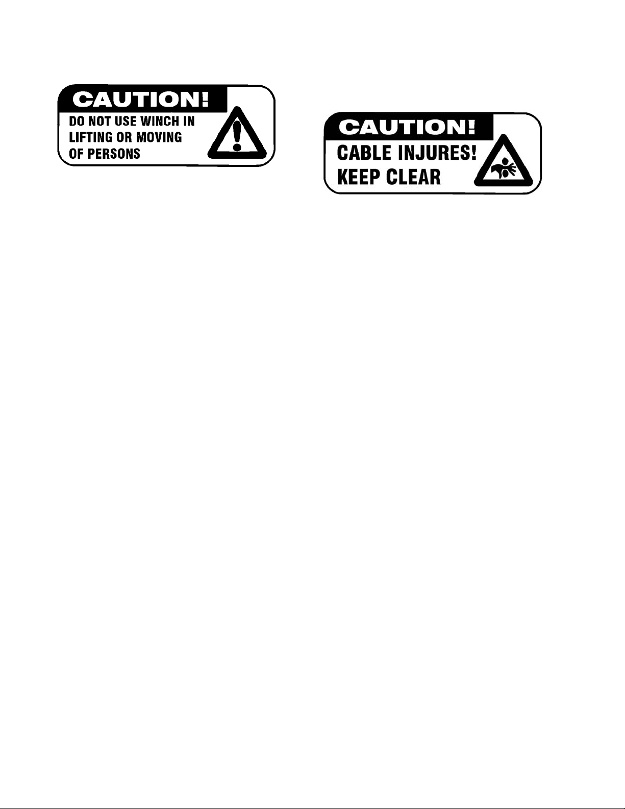
CAUTION: Read and understand this manual before installation and operation of winch. See Safety Precautions.
Page 2
Safety Precautions To Guard Against
Possible Injury…
A minimum of five wraps of cable around the drum barrel is
necessary to hold the rated load. Cable clamp in not designed to hold the load.
A. Keep yourself and others a safe distance to the side of
the cable when pulling under load.
B. Don't step over a cable, or near a cable under load.
C. Use supplied hook strap when handling hook for spool-
ing wire rope.
D. Don't move the vehicle to pull a load on the winch cable.
This could result in cable breakage.
E. Use a heavy rag or gloves to protect hands from burrs
when handling winch cable.
F. Apply blocks to wheels when vehicle is on an incline.
G. Winch clutch should be disengaged when winch is not
in use and fully engaged when in use.
H. Modification, alteration or deviation to the winch should
only be made by Ramsey Winch Company.
I. Keep the duration of your pulls as short as possible. If
the motor becomes uncomfortably hot to the touch, stop
and let it cool for a few minutes. Do not pull more than
one minute at or near rated load. Do not maintain power
to the winch if the motor stalls. Electric winches are for
intermittent usage and should not used in constant duty
applications.
J. Disconnect the remote control switch from the winch
when not in use. A Ramsey Part No. 282053 safety on-
off switch in your vehicle is recommended.
K. Note: Do not use winch in hoisting applications due to
required hoist safety factors and features.
L. Do not exceed maximum line pull ratings shown in ta-
bles. Shock loads must not exceed these ratings.
M. To respool correctly, it is necessary to keep a slight load
on the cable. This is accomplished by (wearing gloves)
holding the cable with one hand and the remote control
switch with the other, starting as far back and in the
center as you can, walking up keeping load on the cable
as the winch is powered in. Do not allow the cable to
slip through your hand and do not approach the winch
too closely. Turn off the winch and repeat the procedure
until all the cable except a few feet is in. Disconnect the
remote control switch and finish spooling in cable by
rotating the drum by hand with clutch disengaged. On
hidden winches, spool in cable under power using supplied hook strap.
Tips for Safe Operation
Don't underestimate the potential danger in winching operations. Neither should you fear them. Do learn the basic dangers and avoid them.
The uneven spooling of cable, while pulling a load, is not a
problem, unless there is cable pileup on one end of drum. If
this happens, reverse the winch to relieve the load and move
your anchor point further to the center of the vehicle. After
the job is done you can unspool and rewind for a neat lay of
the cable.
Store the remote control switch inside your vehicle where it
will not become damaged. Inspect it before you plug it in.
When ready to begin spooling in, plug in remote control
switch with clutch disengaged. Do not engage clutch with
motor running.
Never connect the hook back to the cable. This causes cable
damage. Always use a sling or chain of suitable strength as
shown in the illustrations.
Observe your winch while winching, if possible, while standing at a safe distance. If you use vehicle drive to assist, stop
and get out every few feet to assure the cable is not piling up
in one corner. Jamming cable can break your winch.
Do not attach tow hooks to winch mounting apparatus. They
must attach to vehicle frame.
When double lining during stationary winching, the winch
hook should be attached to the chassis of the vehicle.
Since the greatest pulling power is achieved on the innermost layer of your winch, it is desirable to pull off as much
line as you can for heavy pulls (remember, you must leave 5
wraps min. on the drum). If this is not practical, use a snatch
block and double line arrangement (see illustration).
Neat, tight spooling avoids cable binding, which is caused
when a load is applied and the cable is pinched between two
others. If this happens, alternately power the winch in and
out a few inches. Do not attempt to work a bound cable under load; free by hand.
2
Page 3
Techniques of Operation
The best way to get acquainted with how your winch operates
is to make a few test runs before you actually need to use it.
Plan your test in advance. Remember you hear your winch as
well as see it operate. Get to recognize the sound of light
steady pull, a heavy pull, and sounds caused by load jerking or
shifting. Soon you will gain confidence in operating your winch
and its use will become second nature with you.
Your winch will not only pull your vehicle up or ease your vehi-
cle down a steep grade, it will also pull another vehicle or a
load while your vehicle is anchored in a stationary position.
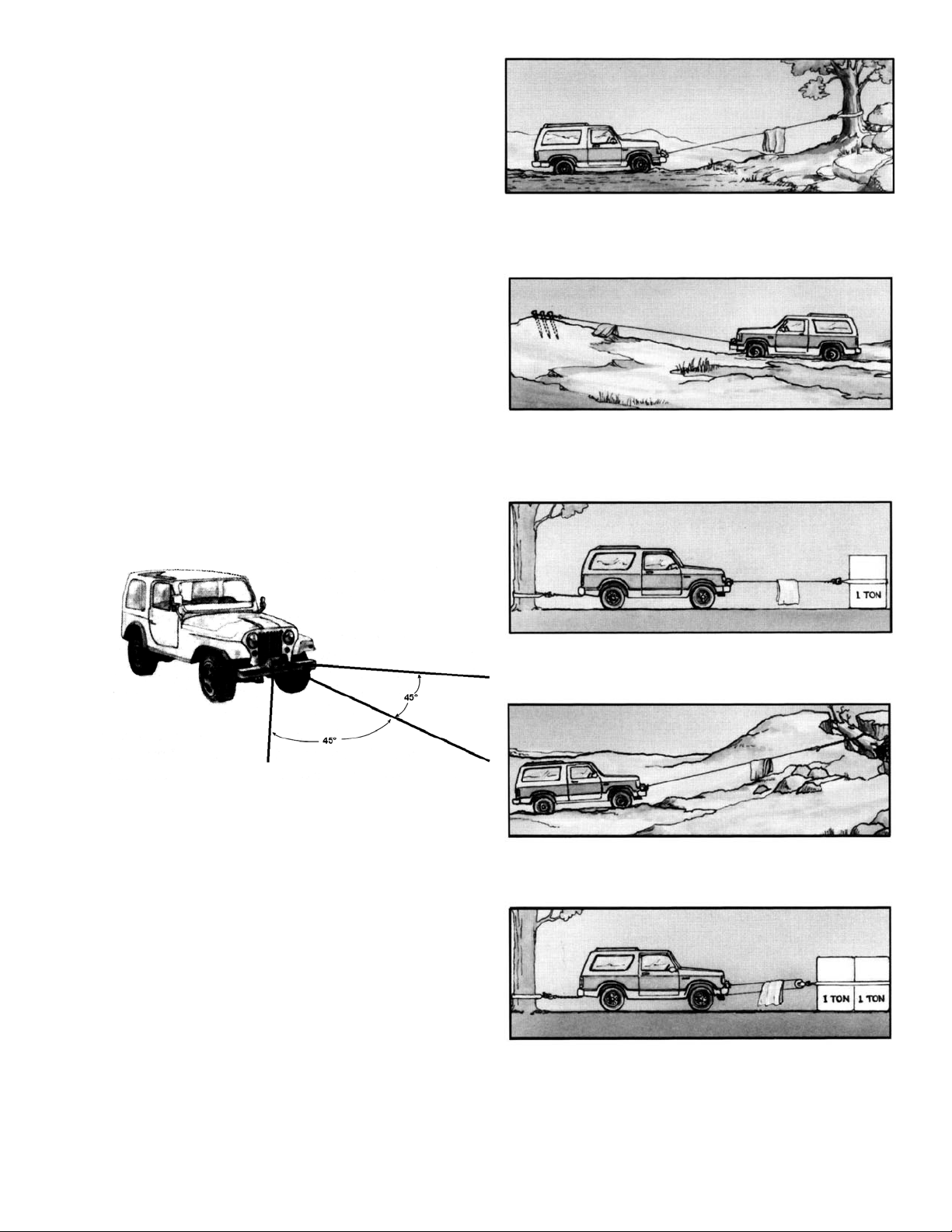
The following sketches show you a few techniques.
When pulling a heavy load, place a blanket, jacket or tarpaulin
over the cable five or six feet from the hook. It will slow the
snap back in the event of a broken cable. Also open the vehicle
hood for additional protection.
For basic self-recovery, anchor to a tree or heavy
rock. When anchoring to a tree, always use a tree
trunk protector.
Use the vehicle wheel power to help the winch, but don't over-
take the winch line. Plan your pull. You can't always hook up
and pull out in one step. Examine all the areas for anchoring
possibilities as well as leverage situations, direction and goal.
Winches equipped with cable guide fairleads can pull
from several directions. Pull from an angle only to
straighten up the vehicle-otherwise you can damage
structural members or other parts of your vehicle and
cause excess cable buildup on one end of the winch
drum.
Stakes driven in solid earth and chained together
make a good anchor point for self-recovery when no
solid anchor point is available.
For a direct pull of 2000 lbs., hitch truck to a tree or
solid anchor, and take out of gear.
For a solid anchor, bury a log with earth or sand or
place it in a deep ravine.
To double the pull, use 2-part line with snatch block
and tie off to chassis. Take out of gear.
3
Page 4
Installation
The winches shown in this owner's manual are solely and
exclusively designed for vehicle mounted, non-industrial applications. All other applications will void warranty.
Note: For specific bull-bar applications, the shifter lever on
the winch may need to be repositioned. Refer to pages 6-7
for instructions in how to do this.
It is very important that the winch be mounted on a flat surface so that the three major sections (the motor end, the
cable drum and the gear housing end) are properly aligned. It
is recommended that Ramsey kits be used to mount the
winch. They are designed to align the winch and distribute
up to the full rated load evenly, to avoid possible damage to
the winch or vehicle. Note: If recommended mounting is not
used, a kit of equal design must be used.
Also available for mounting the REP winches are winch
mounting channels:
P/N: 408052 Short 23.63" (black),
P/N: 408120 Medium 30.00" (black)
Attach fairlead to channel using hardware furnished with
winch (see FIGURE 4). Attach winch to channel. Place (4)
flat washers and nuts into pockets of winch mounting feet
and thread capscrews with lock washers through mounting
holes in channel and into hardware in winch feet.
Substitution of attaching hardware items (bolts, nuts or
washers) different from those supplied with your winch and
mounting kit can lead to failure causing damage or serious
injury (use SAE grade 5 bolts or better and torque to 34 ftlbs.)
Place end of drum cable through fairlead and attach cable
hook. Use clevis pin and cotter pin (see FIGURE 4).
P/N: 408101 Long 36.00" (black)
It is recommended that a Ramsey mounting channel be used
in all non-Ramsey mountings.
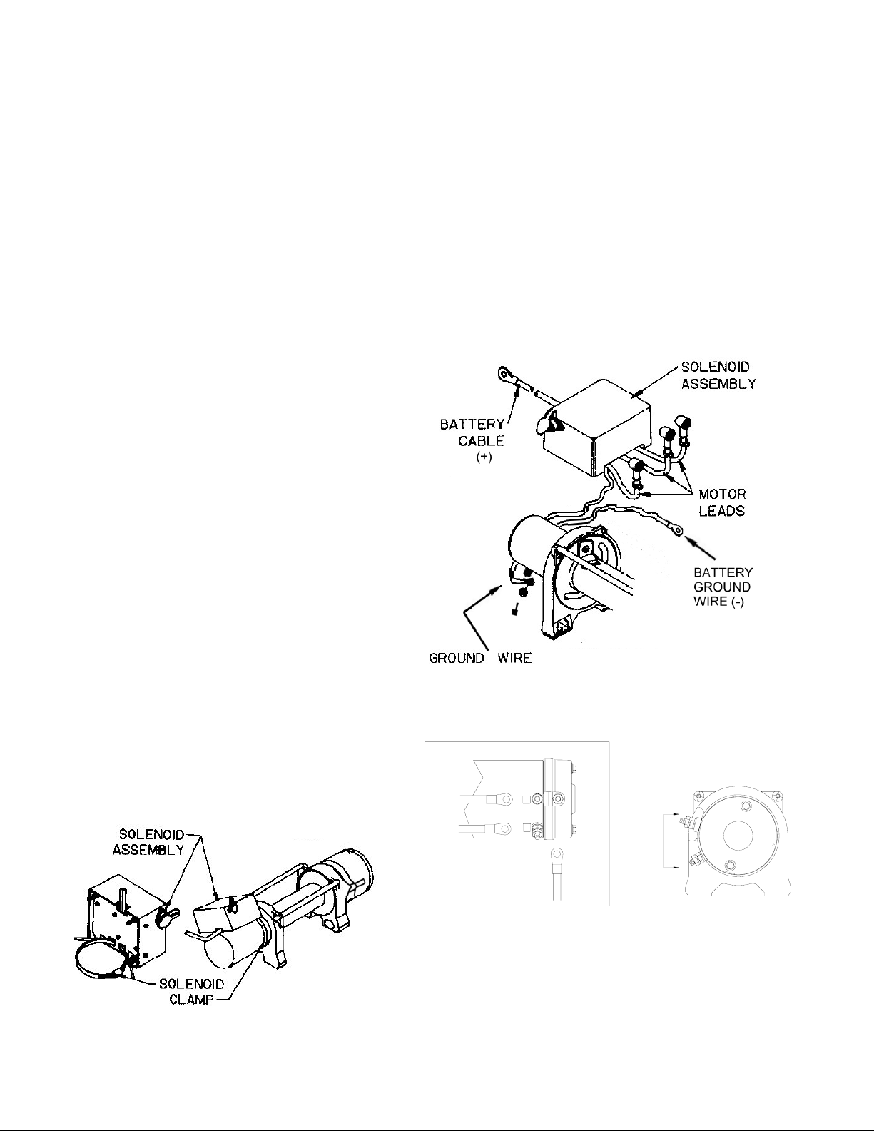
When mounting winch, connect labeled motor leads coming
from solenoid assembly to appropriately marked motor terminals. TIGHTEN NUTS ON MOTOR TERMINALS SECURELY
(see FIGURE 3). Attach solenoid ground wire to grounding
bolt located at bottom of motor (See FIGURE 2). Battery
ground wire is already installed to grounding bolt on motor.
As shown in Figure 1, use solenoid clamp to secure solenoid
assembly to winch motor. If installing in combo mounting
kit, position at about a 45° angle for clearance of lower
winch guard tube in kit. Be sure that clamp is clear of motor
terminals. TIGHTEN CLAMP SECURELY.
FIGURE 2
F1
1
F2
2
A
A
A
FIGURE 1
View A-A
FIGURE 3
4
Page 5
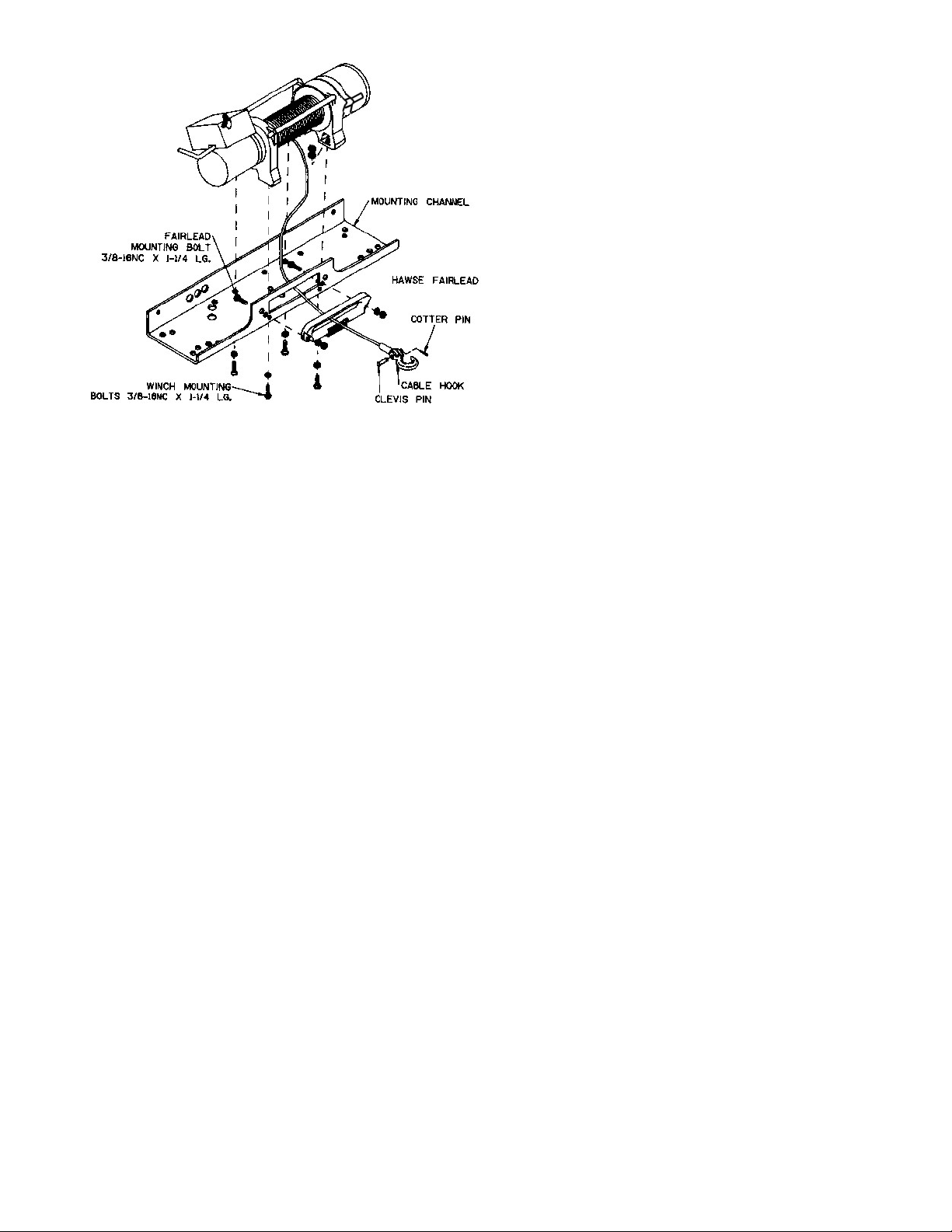
FIGURE 4
Electrical Connections and Operations
For normal self-recovery work, your existing electrical sys-
tem is adequate. Your battery must be kept in good condi-
tion. A fully charged battery and proper connections are es-
sential. Run the vehicle engine during winching operations to
keep battery charged.
The remote control switch is waterproof. It has push button
stations on either side. It is designed this way to prevent
quick winch reversals, which lead to solenoid failure. Make
sure the motor has stopped fully before reversing. To actuate
winch simply plug remote control switch into receptacle in
black solenoid cover of winch.
Run winch forward and reverse to check connection and to
determine winch operating directions. Snap appropriate "IN"
and "OUT" disc into proper thumb cavity. The switch is also
color coded to aid you in not having to guess at the direction
your winch will run. DO NOT LEAVE SWITCH PLUGGED IN
WHEN WINCH IS NOT IN USE.
Route red and black battery cables up to battery. CAUTION:
BE SURE BATTERY CABLES ARE NOT DRAWN TAUT
ACROSS ANY SURFACES WHICH COULD POSSIBLY DAM-
AGE THEM. Connect red cable to positive (+) battery termi-
nal and black cable to negative (-) terminal.
5
Page 6
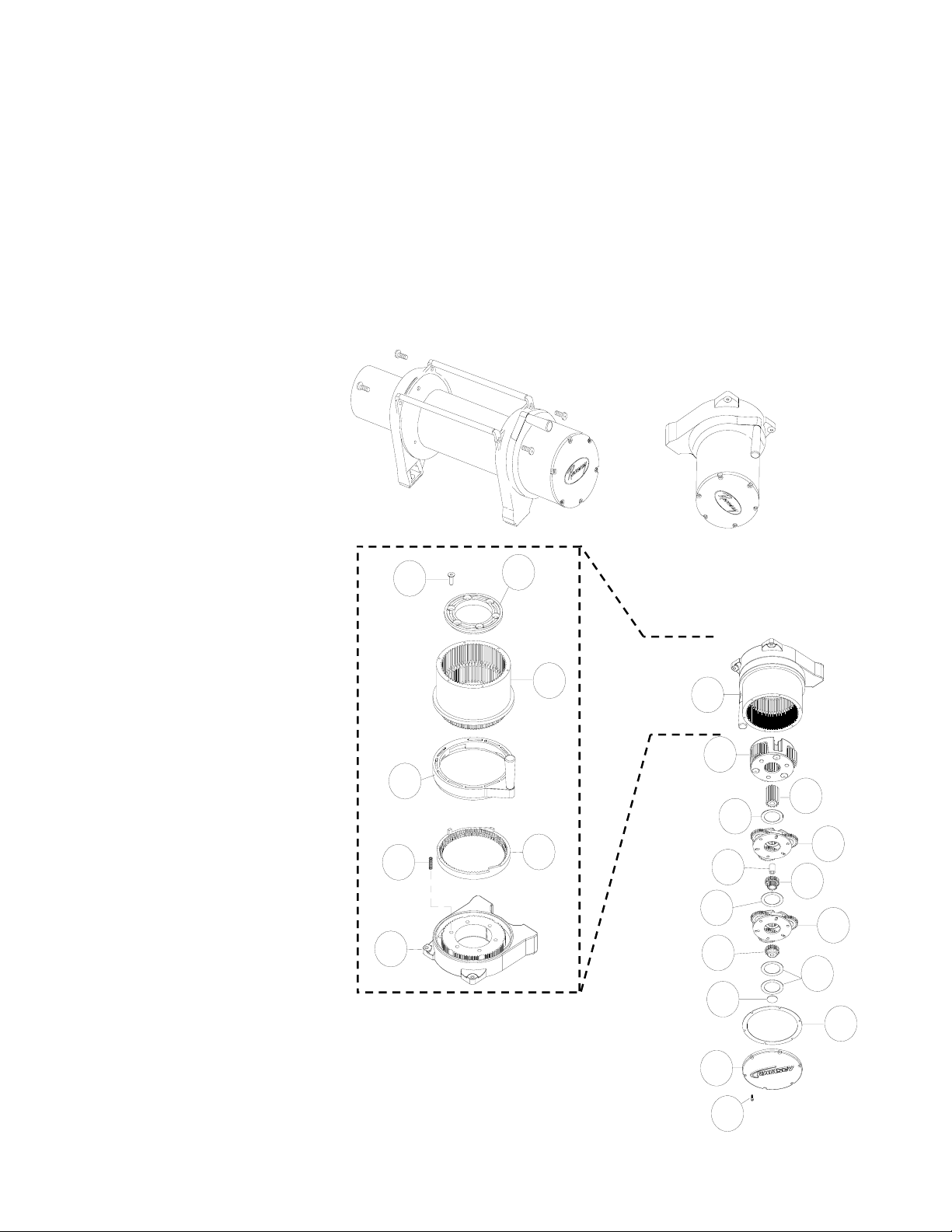
Repositioning Shifter for Specific Bull Bar Applications
Note: The shifter is positioned correctly for most applications. It will only need to be repositioned as necessary for specific
bull bar applications.
Refer to the Parts List and Exploded Parts Diagram for your specific winch elsewhere in this owner’s manual.
1. Position winch as shown in Figure 5. Remove screws from tiebars. You may be able to loosen the screws at the motor
end without removing them. Pull the Gear Housing assembly from the drum and shaft and set it down on the work
bench with the Gear Housing Cover up. Remove the drum bushing from the Gear Housing assembly or the end of the
drum. Set aside.
2. Remove (6) capscrews from the Gear Housing Cover. Holding the Gear Housing Cover over the Gear Housing assem-
bly, flip it over and set it on the workbench.
3. Gently lift the Gear Housing assembly,
working the gears, bushings, etc. that
are inside the Gear Housing out so that
they are left stacked on the workbench.
See Figure 7.
4. Turn the Gear Housing assembly over
and set on workbench. Remove the Re-
tainer (item #38) by removing six cap-
screws (item #22) from Gear End Bear-
ing (item 16). Once the retainer is re-
moved, the Ring Gear (items #15 &31),
Cam Ring (item #36), and Locking Ring
(item #35) can be lifted off the end
bearing.
Remove the six springs (item #39) from
the end bearing.
FIGURE 5
22
36
39
16
FIGURE 6
38
35
15
15
2
14
40
3
18
12
40
1
13
40
41
29
6
10
24
FIGURE 7
Page 7
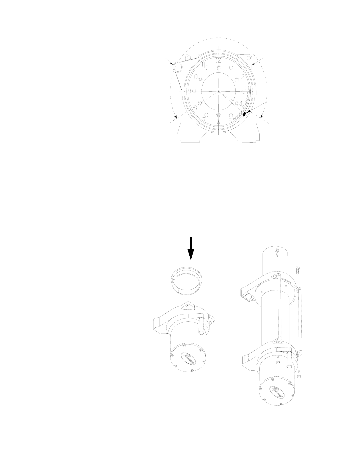
5. Determine position shifter knob needs to
be for your application. Note: Shifter
RANGE OF POSITION
FOR SHIFTER KNOB
knob cannot be positioned too low or it
will interfere with the feet on the Gear
End Bearing (see Range of Position in
Figure 8).
CAM RING
SHIFTER
KNOB
END BEARING
6. To position the shifter knob, place locking ring in end bearing with stop post
approximately 180° from where shifter
knob needs to be positioned. Place cam
ring over locking ring in proper position
STOP POST ON
RING GEAR LOCK
and confirm that shifter knob will move
from engaged to disengaged position
without interference. Mark position of
stop post on end bearing.
FIGURE 8
7. Remove cam ring and locking ring from end bearing. Insert springs (item #39) into end bearing. When you replace the
locking ring (item #35) over the springs, be sure the springs compress down into their recesses, and don’t bend sideways.
8. Reassemble Gear Housing as shown in Figure 7. Make sure locking ring is positioned with stop post at marked location. The capscrews (item #22) for the retainer should be tightened to 40-45 in-lbs. Do not over-tighten.
9. Place Gear Housing over the stacked gears, etc. that you removed in step 3. Gently work the housing over the stack,
turning it as needed to mesh the planetary gears with the ring gear in the housing. Once they are all in the housing, flip
the assembly over. Align the Gear Housing Cover and gasket with the holes in the ring gear. Replace the (6) capscrews
that hold the Gear Housing Cover onto the Gear Housing. Tighten securely.
10. Move the Shifter to the Disengaged position.
11. Turn the Gear Housing over and set it on the
work bench with the Gear Housing Cover
down. See Figure 9.
12. Install the drum bushing into the Gear Housing, confirming that the slot in the bushing is
aligned with the key in the end bearing. Pick
up the rest of the winch (drum and motor
end), and holding the drum, lower the winch
onto the gear end. Stab the shaft into the
gear end--you may need to turn the drum
slightly to get the shaft to go all the way in.
13. Place the tiebars on the motor end and gear
end and fasten using (4) screws. Tighten
securely.
14. Once the winch is reassembled, turn it so
that it is sitting on its feet. Confirm that the
cable will freespool when the shifter is in the
Disengaged position. Connect up the winch
temporarily and confirm that the cable
spools when the shifter is in the Engaged
position.
FIGURE 9
7
Page 8

Maintenance
All moving parts in the winch are permanently lubricated with
high temperature lithium grease at the time of assembly.
Under normal conditions factory lubrication will suffice.
Lubricate cable periodically using light penetrating oil. Inspect for broken strands and replace if necessary with Ramsey part number listed in Parts List. If the cable becomes
worn or damaged, it must be replaced.
Corrosion on electrical connections will reduce performance
or may cause a short. Clean all connections especially in the
remote control switch and receptacle. In salty environments
use a silicone sealer to protect from corrosion.
To minimize corrosion of the internal motor components that
may occur due to condensation, power the winch in or out
periodically. Energizing the motor will generate heat, which
will help dissipate any moisture buildup in the motor. This
should be performed at periodic intervals (such as with each
oil change to your vehicle). Note: Refer to the Troubleshooting Guide if the motor has been submerged.
Cable Installation
Unwind the new cable by rolling it out along the ground, to
prevent kinking. Remove old cable and observe the manner
in which it is attached to the cable drum flange.
Operating Instructions
The winch clutch allows rapid unspooling of the wire rope for
hooking onto the load or anchor point. The clutch shifter tab
is located on the gear-housing end of the winch and operated as follows:
1. To disengage the clutch, move the clutch shifter tab to
the "OUT" position. Wire rope may now be free-spooled
off the drum.
2. To engage the clutch, move the clutch shifter tab to the
"IN" position. The winch is now ready for pulling.
Before installing the new cable assembly, make sure end of
cable is squarely cut and wrapped with tape to prevent fraying. Form a short 90° bend (approximately ½" long) in the
end of the cable.
Position the cable drum so that the large 13/32" diameter
hole in the motor end drum flange is approximately on the
top. Insert the bent end of cable into the 13/32" hole in the
drum flange and then carefully run the winch in the "reel in"
direction approximately ¾ revolution until the ¼" diameter
threaded hole in the drum flange is on top. Secure the cable
to the drum flange using cable anchor and capscrew shown
in the parts drawing. Securely tighten the capscrew, but do
not over-tighten.
Wind 5 wraps of cable onto the drum. Winch on the rest of
the cable by pulling in a light load to keep the tension constant. Allow the cable to swivel by using a length of chain or
a block between the cable hook and the load.
8
Page 9

Troubleshooting Guide
CONDITION POSSIBLE CAUSE CORRECTION
MOTOR RUNS IN ONLY ONE
DIRECTION
MOTOR RUNS EXTREMELY
HOT
MOTOR RUNS, BUT WITH
INSUFFICIENT POWER, OR
WITH LOW LINE SPEED
MOTOR RUNS, BUT DRUM
DOES NOT TURN
MOTOR WILL NOT OPERATE (1) Defective solenoid or stuck solenoid (1) Jar solenoid to free contacts. Check solenoid by ap-
(1) Defective solenoid or stuck solenoid (1) Jar solenoid to free contacts. Check by applying 12
volts to coil terminal (it should make an audible click
when energized).
(2) Defective remote control switch (2) Disengage winch clutch, remove remote control
switch plug from the socket and jump pins at 8 and 4
o’clock. Motor should run. Jump pins at 8 and 10
o’clock. Motor should run.
(1) Long period of operation (1) Cooling-off periods are essential to prevent overheat-
ing.
(1) Insufficient battery (1) Check battery terminal voltage under load. If 10 volts
or less, replace or parallel another battery to it.
(2) Bad connection (2) Check battery cables for corrosion; clean and grease.
(3) Insufficient charging system (3) Replace with larger capacity charging system.
(1) Clutch not engaged (1) If clutch engaged but symptom still exists, it will be
necessary to disassemble winch to determine cause
and repair
plying 12 volts to coil terminal (it should make an
audible click when energized).
(2) Defective remote control switch (2) Disengage winch clutch, remove remote control
(3) Defective motor (3) If solenoids operate, check for voltage at armature
(4) Loose connections (4) Tighten connections on bottom side of hood and on
MOTOR WATER DAMAGED (1) Submerged in water or water from
high pressure car wash
CABLE DRUM WILL NOT
FREESPOOL OR IS DIFFICULT TO FREESPOOL
(1) Clutch not disengaged (1) Check clutch operation according to nameplate. Make
(2) Winch not mounted squarely causing
end bearing to bind drum
(3) Some or all of the (6) 414861 flat
head capscrews attaching the
479007 ring gear retainer are too
tight
switch plug from the socket and jump pins at 8 and 4
o’clock. Motor should run. Jump pins at 8 and 10
o’clock. Motor should run.
post; replace motor
motor
(1) Allow to drain and dry thoroughly, then run motor
without load in short bursts to dry windings.
sure clutch shifter knob is fully at “OUT” position.
(2) Check mounting to see that installation instructions on
page 4 have been followed.
(3) Remove the gear housing cover, 413018, and all
gears from inside the gear housing. Disengage the
clutch and check to see that the ring gear will rotate
by hand. If it will not, using a hex (allen) wrench,
slightly loosen all the capscrews and then snugly retighten them in cross-cross pattern, but do not over
tighten. The ring gear must rotate by hand. Reassemble the winch.
9
Page 10
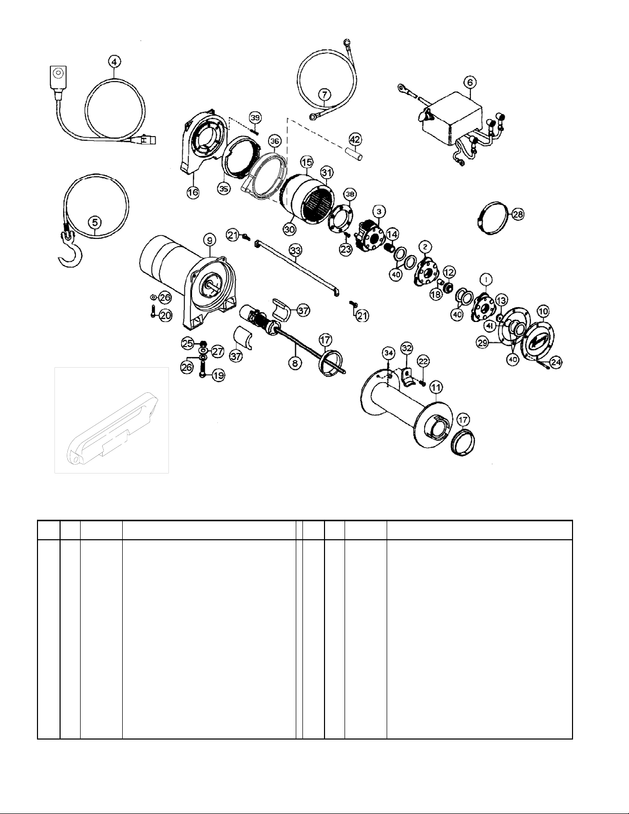
r
r
r
r
r
r
Hawse Fai rlead
Replacement Kit #251152
REP 9.5e PARTS LIST
Item
Qty. Part No. Description
No.
1 1 247009 Gear Carrier Ass’y.-Input 22 1 414830 Capscrew 1/4-20NC x 3/8 Lg. Soc. Button Hd.
2 1 247022 Gear Carrier Ass’y-Intermediate 23 6 414861 Capscrew 1/4-20NC x 3/4 Lg. Flat Hd. Soc. NYLOK
3 1 247023 Gear Carrier Ass’y-Output 24 6 414868 Capscrew 1/4-20NC x 2-1/2 Lg. Flat Hd. Soc. NYLOK
4 1 251110 Switch Ass’y 25 4 418035 Nut 3/8-16NC Hx. Reg. Z/P
5 1 251118 Cable Assembly 26 5 418177 Lockwasher-3/8 Med. Sect. Z/P
6 1 278158 Solenoid Ass’y 27 4 418181 Washer-Flat 3/8 ID S.A.E. Z/P
7 1 289141 Cable-Ground 28 1 424023 Clamp
8 1 296181 Brake/Shaft Ass’y 29 1 442208 Gasket-Cove
9 1 296589 Motor Assembly 30 1 442219 Gasket-Ring Gea
10 1 328138 Cover-Gear Housing 31 1 444077 Gear-Ring, Input
11 1 332193 Drum-Cable 32 1 448046 Cable Anchor
12 1 334147 Gear-Intermediate Sun 33 2 448049 Tie Ba
13 1 334154 Gear-Input Sun 34 1 470053 Roll Pin-1/8 Dia. x 3/8 Lg.
14 1 334197 Gear-Output Sun 35 1 477002 Locking Ring
15 1 334171 Gear-Ring, Output 36 1 477013 Cam Ring
16 1 338332 End Bearing 37 2 477004 Ring-Half
17 2 412056 Bushing-Drum 38 1 479007 Retainer-Ring Gea
18 1 412061 Bushing-Shaft 39 6 494077 Spring
19 4 414316 Capscrew 3/8-16NC x 1-1/4 Lg. Hx. Hd. Gr.5, Z/P 40 6 518020 Thrust Washe
20 1 414370 Capscrew 3/8-24NF x 1/2 HX HD ZP GR5 41 1 518027 Thrust Disc
21 4 414823 Capscrew 1/4-20NC x 3/4 Lg. Soc. Button Hd. 42 1 452005 Shifter Leve
Item
Qty. Part No. Description
No.
10
Page 11
r
r
r
r
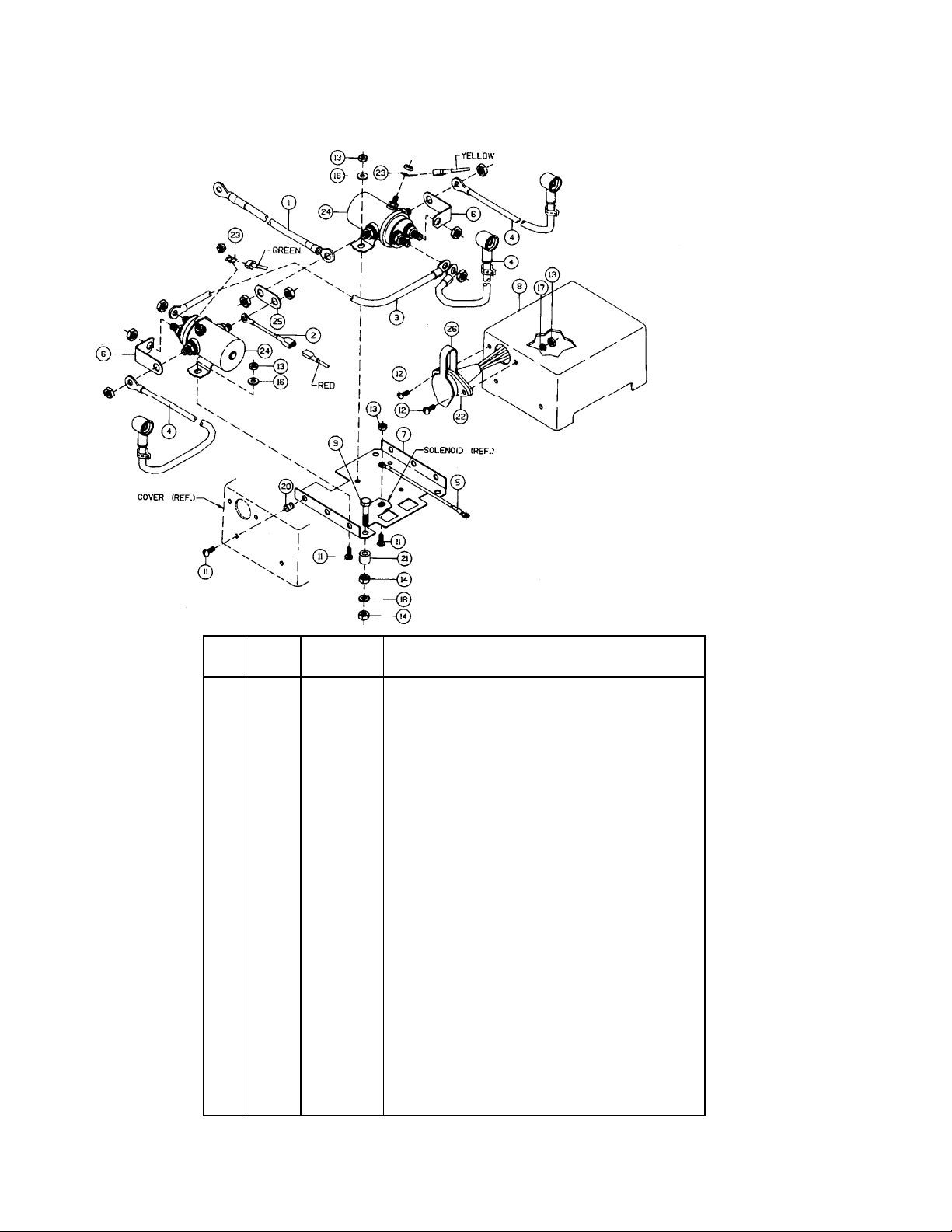
Solenoid Assembly Parts List
278158 (12V)
Note: All unidentified hardware comes
supplied with the solenoid.
Item
No. Qty. Part No. Description
1 1 289015 Wire Assembly—Battery Red 72"
2 1 289091 Wire Assembly—Black 16 Ga. x 1-1/2” Lg.
3 1 289092 Wire Assembly—Black 6 Ga. x 3-1/2” Lg
4 3 289171 Wire Assembly—Motor Lead
5 1 289208 Wire Assembly—Ground
6 2 364002 Strap—Coppe
7 1 408102 Bracket
8 1 413024 Cover—Solenoid
9 3 414053 Capscrew 1/4—20NCx1-1/4Lg.Hx.Hd. Z/P
11 7 416216 Screw #10—24NCX 1/2” Lg. Rd. Hd. Z/P
12 2 416227 Screw #10—24NCX 3/4” Lg. Truss Hd. Black
13 6 418004 Nut—Hx. Reg. #10—24NC Z/P
14 6 418014 Nut—Hx. Reg 1/4—20NC Z/P
16 3 418140 Washer #10 SAE Flat Z/P
17 2 418141 Lockwasher #10 Med. Sect. Z/P
18 3 418149 Lockwasher 1/4 Med. Sect. Z/P
20 3 418411 Nutsert #10—24NC
21 3 418514 Space
22 1 430013 Connector Female—Molded
23 2 440071 Terminal Tab
24 2 440110 Solenoid
25 1 440111 Strap—Coppe
26 1 482029 Cover—Female Connecto
11
Page 12
Warranty Information
Ramsey Winches are designed and built to exacting specifications. Care and skill go into every winch we make.
If the need should arise, warranty procedure is outlined on the back of your self-addressed, postage paid warranty card. Please read and fill out the enclosed warranty card and send it to Ramsey Winch Company. If you
have any problems with your winch, please follow instructions for prompt service on all warranty claims.
Limited Lifetime Warranty
Ramsey Winch offers a limited lifetime warranty for each new Ramsey
winch against manufacturing defects in workmanship and materials on all
manufactured components.
Warranty registration cards for each winch must be submitted at the time
of purchase or within 30 days. Warranty will only be valid for the original
purchaser of the winch and installed on the vehicles with which they were
originally registered.
New cable assemblies are warranted against defects in workmanship and
materials. No warranty applies after initial use.
All Ramsey mounting kits and other accessories carry a one year limited
warranty against defects in materials and workmanship.
This warranty is void if winch is used in commercial/industrial applications
other than front mount self recovery.
Electrical components consisting of motors, solenoids, wiring, wire connectors, and associated parts carry a limited 1-year warranty. Battery
isolators carry a 90-day limited warranty.
The obligation under this warranty, statutory or otherwise, is limited to the
replacement or repair at the manufacturers factory, or at a point designated by the manufacturer, of such part as shall appear to the manufacturer, upon inspection of such part, to have been defective in material or
workmanship. This Warranty does not obligate Ramsey Winch Company
to bear the cost of labor or transportation charges in connection with the
replacement or repair of defective parts, nor shall it apply to a product
upon which repairs or alterations have been made, unless authorized by
the manufacturer, or for equipment misused, neglected or improperly
installed.
Important notice: To the fullest extent permitted by applicable law,
the following are hereby excluded and disclaimed: 1. All warranties
of fitness for a particular purpose; 2. All warranties of merchantability; 3. All claims for consequential or incidental damages. There
are no warranties that extend beyond the description that appears
on the face hereof.
Some states do not allow the above exclusions or disclaimers in
consumer transactions and as such this disclaimer/exclusion may
not apply to your particular case.
To the extent such warranties of fitness for a particular purpose or
merchantability are deemed to apply to this product, they exist only
for so long as the express limited warranty elsewhere set forth is in
existence.
Ramsey Winch Company makes no warranty in respect to accessories,
same being subject to the warranties of their respective manufacturers.
Ramsey Winch Company, whose policy is one of continuous product
improvement, reserves the right to improve any product through changes
in design or materials as it may deem desirable without being obligated to
incorporate such changes in products of previous manufacture.
If field service at the request of the buyer is rendered and the fault is found
not to be with Ramsey Winch Company’s product, the buyer shall pay the
time and expense of the field representative. Bills for service, labor or other
expenses which have been incurred by the buyer without express approval
or authorization by Ramsey Winch Company will not be accepted.
This warranty gives you specific legal rights and you may also have other
legal rights which vary from state to state.
RAMSEY WINCH COMPANY
P.O. BOX 581510 • TULSA, OKLAHOMA 74158-1510 • USA
PHONE (918)438-2760 • FAX (918)438-6888
Visit us at http://www.ramsey.com
914162-0107-D
12
 Loading...