

STP4PL • STP6PL • STP9PL
STP Plus Controller
Installation, Programming
& Operation Guide

Simple to Program Plus Controller
Installation, Programming, and Operation Guide
Contents
Safety and Regulatory Information ............................................................. 2
Introduction ................................................................................................. 3
Welcome to Rain Bird ....................................................................................... 3
Controller Features ..........................................................................................3
Controller Functions ........................................................................................ 4
Programming ...............................................................................................6
Set Clock ............................................................................................................ 6
Set Date ............................................................................................................. 6
Schedule Watering ........................................................................................... 7
Manual Water Zone .......................................................................................... 9
Manual Water All ............................................................................................ 10
Rain Delay .......................................................................................................11
Adjust Water ................................................................................................... 12
Normal Operations ........................................................................................13
Installation .................................................................................................14
Mount Controller............................................................................................14
Connect Field Valve Wires ............................................................................. 15
Install Master Valve or Pump Start Relay .................................................... 16
Connect Rain Sensor ...................................................................................... 18
Connect Power................................................................................................19
Troubleshooting .........................................................................................20
Watering Issues ..............................................................................................20
Electrical Issues .............................................................................................. 21
Reset ................................................................................................................ 21
Programming Chart ................................................................................... 22
Declaration of Conformity .........................................................................23
STP Plus Controller
1

Safety and Regulatory Information
Symbols
NOTE: Symbol alerts the user to important
operating, functionality, installation or
maintenance instructions.
WARNING: Symbol alerts the user to the presence
of electricity or electromagnetic energy which may
constitute a risk of electric shock, radiation exposure
or other hazard.
CAUTION: Symbol alerts the user to important
instructions or conditions that could seriously
aect irrigation eectivity or device operation.
DIAL: Symbol alerts user of requirement to turn
the dial on the device to an appropriate setting in
order to follow subsequent instructions.
REPEAT: Symbol indicates that a repetition of
previous steps or actions may be required in
order to continue or complete the process of
programming the device.
Safety Information
WARNING: Date and time are retained by a lithium
battery which is to be disposed of in accordance with
local regulations.
Regulatory Information
This equipment has been tested and found to comply
with the limits for a Class B digital device, pursuant
to Part 15 of the FCC Rules. These limits are designed
to provide reasonable protection against harmful
interference in a residential installation.
Disposal of Electronic Waste
This symbol indicates that it is your responsibility to
dispose of waste equipment (including batteries) by
handing it over to a designated collection point for the
recycling of waste electrical and electronic equipment.
For more information about where you can drop o your
waste equipment for recycling, please contact your local
city oce, your waste disposal service or the shop where
you purchased the product.
For technical assistance contact Rain Bird at 1-800-247-3782.
Visit us on the web at www.rainbird.com
STP Plus Controller
2

Introduction
Welcome to Rain Bird
Thank you for Purchasing the Rain Bird Simple To
Program Controller! In the following pages, you
will nd step by step instructions on how to use
every function included in your STP Plus Controller.
Thanks again and we hope you enjoy your new
Controller.
Controller Features
Rain Bird’s Simple-to-Program (STP) controllers
are indoor controllers that have 4, 6 or 9 zone
capability. Custom irrigation schedules are entered
for each zone to match specic irrigation needs.
Simple to use “At-a-Glance” programming displays
all of the irrigation schedule information for each
specic zone at the same time on the controller.
Key features of the STP Plus Controller:
Independent zone control gives the
exibility to create individual, specic
watering schedules for each zone.
The STP Plus controller provides multiple
start times per day (with user selectable
osets) on an individual zone basis.
The Adjust Water feature allows the increase
or decrease of irrigation run times for all
zones quickly.
In the event of a prolonged rain, the irrigation
schedule can be delayed up to 72 hours
using the controller’s Rain Delay feature.
The Water All and Water Zone buttons
manually water all zones or a specic zone
without impacting any zone’s previously
set schedule.
To help manage water restrictions, the
controller can be set up to only water on
specic days of the week or “odd or even” days.
The irrigation schedule is saved in the
controller’s non-volatile memory in case
there is a power outage. Date and time are
stored with an internal lithium battery for
up to seven days.
Extra 24 volt terminals are available on
the terminal strip to allow attachment of a
Wireless Rain Sensor (not included) or other
powered accessories.
STP Plus Controller
3
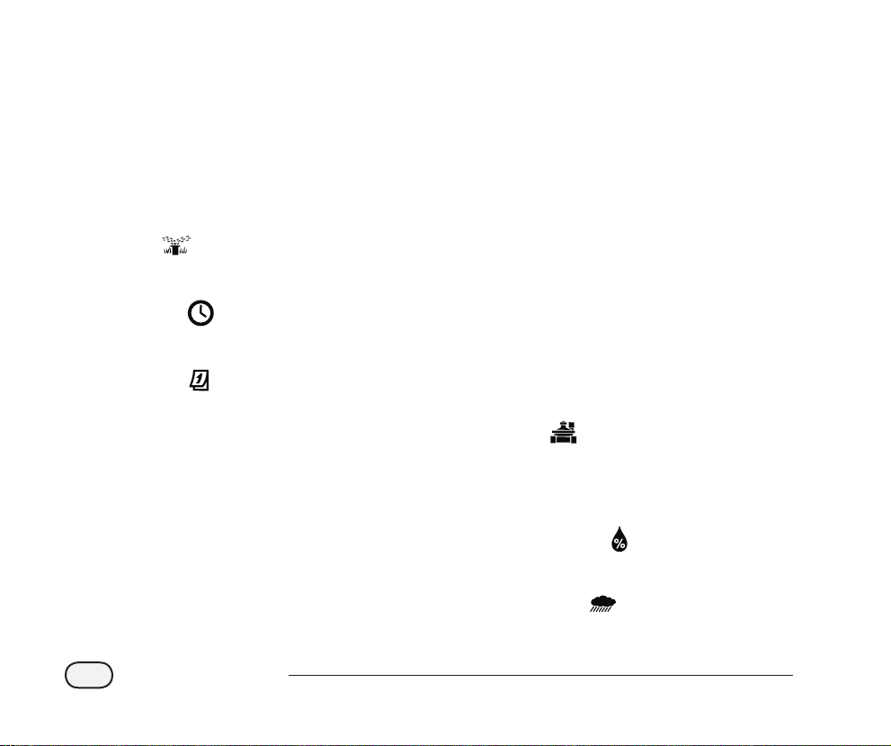
Controller Functions
This section is a guide to the displays,
controls, and indicators on the STP Plus
Controller.
OFF
A
Turns o all watering features.
AUTO
B
Set dial here to run all programmed settings.
SET TIME
C
Set current time of day.
SET DATE
D
Set current date.
DISPLAY SCREEN
E
LCD displays program information and
status.
WATER DAYS
F
Select which day(s) the displayed zone is
watered.
CYCLES PER DAY
G
Select how many times per day the
displayed zone is watered, and determines
the delays between multiple start times.
ZONE OFF
H
Shuts o the displayed watering zone.
UP/DOWN ARROWS
I
Use UP/DOWN arrows on left or right to set
time, date, run time, 1st start time, etc.
WATER ZONE
J
Manually waters an individual zone.
WATER ALL
K
Manually waters all zones.
ZONES
L
Select individual zone to program. (4 Zone
model is shown, 6 and 9 zone models are
available.)
ADJUST WATER
M
Adjusts watering amount (%).
STP Plus Controller
4
RAIN DELAY
N
Delays watering for up to 72 hours.

1 2 43
5 6
7
14
13
12
11
10
9
8
STP Plus Controller
5
Programming
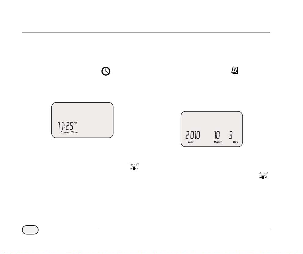
Set Clock
To input the correct time into the Controller,
follow these steps:
Turn the dial to SET TIME
The Current Time screen appears. Use the
A
left UP/DOWN arrows to adjust the time.
(Verify that the AM/PM setting is correct.)
NOTE: Press and hold the UP/DOWN arrow
to accelerate settings.
When nished, turn the dial to AUTO
Set Date
To input the correct date into the Controller,
follow these steps:
Turn the dial to SET DATE
The Current Date screen appears. Use the
A
left UP/DOWN arrows to adjust the year.
Use the right UP/DOWN arrows to adjust the
B
month and day.
NOTE: Press and hold the UP/DOWN arrow
to accelerate settings.
When nished, turn the dial to AUTO
STP Plus Controller
6
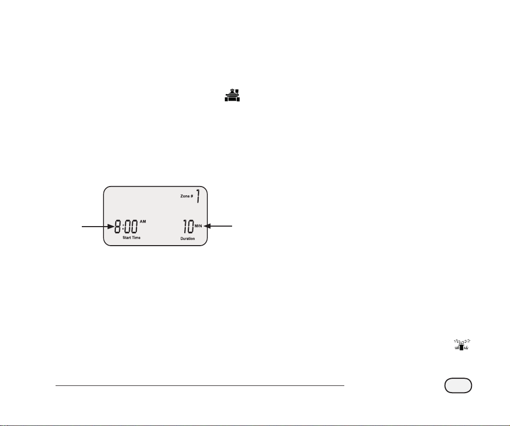
Schedule Watering
To set up a watering schedule for each zone,
follow these steps:
Using the WATER DAYS buttons on the right
C
side of the controller, select the days (or only
ODD/EVEN days) of the week for the zone to
be watered.
Turn the dial to the desired ZONE
The Schedule Watering screen appears with
A
the selected zone displayed. Use the left
UP/DOWN arrows to program the watering
Start Time.
Use the right UP/DOWN arrows to program
B
the Duration (run time) for the selected zone.
1
NOTE: The STP Plus Controller is designed
to prevent any two zones from watering
at the same time. This feature is called
“Program Stacking”. If more than one zone
is scheduled to irrigate at the same time,
the next zone will begin irrigating when the
previous zone has nished.
2
NOTE: The days that are currently selected
for watering will be lit. Press the button to
enable or disable watering for a specic
day. If the ODD (1,3,5) or EVEN (2,4,6) button
is selected, all other days of the week will
automatically turn o.
Using the CYCLES PER DAY buttons, select
D
the number of times per day to water. The
default setting is one time per day. (The
ZONE OFF button will turn o watering for
that zone.)
NOTE: If a multiple start times (2X, 3X, 4X)
button is selected, there are several userselectable osets (hours from rst start time)
available. Successive presses of a CYCLES
PER DAY button will cycle through the list of
available osets (see Table 1). The selected
oset will be displayed on the screen.
Turn the dial to each active zone and repeat
steps 1-4.
When nished, turn the dial to AUTO
STP Plus Controller
7

Table 1 - Watering Time Offsets
3 4
Cycles
Per Day
2X +6 , +1, +2, +3, +4, +8, +9, +12
3X +4 +8 +3 +6
4X +3 +6 +9 +2 +4 +6
List of Available Watering Time Offsets (Hours)
for each Cycles Per Day button
+1 +2 +6 +12
+1 +2 +3 +4 +8 +12
NOTE: Successive presses of a CYCLES PER DAY button
will cycle through the list of available osets. Examples
of multiple watering start times are provided in Table 2.
Table 2 - Watering Start Times with Offsets
Cycles Offset 1st 2nd 3rd 4th
2X +3 8:00 AM 11:00 AM - -
3X +4 +8 8:00 AM 12:00 PM 4:00 PM -
4X +2 +4 +6 12:00 PM 2:00 PM 4:00 PM 6:00 PM
Display with a Watering Time Offset selected:
STP Plus Controller
8
User-Selected Offset

Manual Water Zone
This option can be used to water any single
zone on demand instead of waiting for the
programmed schedule:
Turn the dial to the desired ZONE
The Schedule Watering screen appears with
A
the selected zone displayed.
Press the ZONE button to start watering for
B
a default 10 minutes.
ZONE
Button
The display will show the current watering
C
zone and the time remaining.
Use the right UP/DOWN arrows to increase
D
or decrease the watering time remaining.
To stop watering before the time is up, turn
E
the dial to OFF .
NOTE: This function will not aect the
normal watering schedule.
STP Plus Controller
9

Manual Water All
This option can be used to water all zones
consectutively instead of waiting for the
programmed schedule:
The display will show the current watering
C
zone and the time remaining. When the
current zone completes watering, the next
zone will begin.
Turn the dial to AUTO
The AUTO screen appears.
A
Press the ALL button to start watering. The
B
rst zone will start watering for its currently
programmed run time.
ALL
Button
STP Plus Controller
10
To end irrigation on the current zone before
D
it is complete and advance to the next zone,
press the ALL button.
To stop watering before the time is up, turn
E
the dial to OFF.
NOTE: This function will not aect the
normal watering schedule.

Rain Delay
This option can be used to suspend watering
for up to 3 days (72 hours) due to weather or
other reasons:
Turn the dial to RAIN DELAY
The Rain Delay screen appears. Use the right
A
UP/DOWN arrows to adjust the amount of
delay time.
Turn the dial to AUTO The current time
B
and the number of rain delay hours that are left
until scheduled watering resumes is displayed.
NOTE: Once the Controller has waited the
amount of time you select for Rain Delay, it
will resume normal scheduled watering. Any
scheduled watering that falls into the delay
period will not occur.
STP Plus Controller
11

Adjust Water
This option can be used to make run time
adjustments that account for seasonal
weather variation, without changing the
initial zone settings:
Turn the dial to ADJUST WATER
The Adjust Water screen appears. Use
A
the left UP/DOWN arrows to adjust the
percentage increase or decrease to all zone
run time settings.
NOTE: If a zone is scheduled to water for
10 minutes and you set ADJUST WATER
to +50%, then the zone run time will be
increased to 15 minutes. Scheduled start
times will not be aected.
It is important to note that the baseline
schedule is set at 0% and not 100%.
When an ADJUST WATER value is entered,
the percentage is displayed on the AUTO
screen.
When nished, turn the dial to AUTO
STP Plus Controller
12

Normal Operations
When programming is complete and the dial
is placed in AUTO, the screen will display one
of the following:
Normal Operation
The screen displays current time, the zone that is
scheduled to be watered next, and the date and
time it will be watered.
With Rain Delay
Screen displays current time and the number
of rain delay hours that are left until regularly
scheduled watering resumes.
Watering Now
Screen displays current time, which zone is
currently being watered, and the number of
minutes remaining in the cycle for that zone
Error Detected
When an error is detected, the aected
Zone is displayed in upper-left corner.
STP Plus Controller
13

Installation
Mount Controller
Mount the STP Plus Controller in an accessible location indoors.
Drive a screw into the wall, leaving an 1/8"
A
gap between the screw-head and the wall.
(Use the supplied wall anchors if necessary).
Locate the plastic bracket on the back of
B
the controller, and hang it securely on the
exposed screw.
Remove the wiring bay cover at bottom of
C
controller and drive a screw through the
center hole as shown.
1
2
3
STP Plus Controller
14

Connect Field Valve Wires
Connect the valve wiring for every zone to the STP Plus controller.
2
Connect the valve power
A
wire from each zone to the
corresponding zone number on
the terminal block.
Every zone valve should be
B
connected to one common
wire. Connect this common
wire to one of the COMMON
terminals.
Zone 3
Zone 2
1
Zone 1
STP Plus Controller
15

Install Master Valve or Pump Start Relay
This example shows a typical Master Valve connection. A Pump Start Relay connects to the
controller the same way, but connects differently at the water source.
STP Plus Controllers allow a Master Valve
or Pump Start Relay to operate whenever
a valve is operating (pumps are used in
some places to draw water from a well
or other source). If you are activating a
pump from the controller, you must install
a Pump Control Relay.
NOTE: The controller does NOT
provide main power for a pump.
Connect the color-coded “hot” wire
A
from the Master Valve (or Pump Start
Relay) to the controller terminal
marked MSTR VALVE.
Connect the common wire (usually
B
white) from the Master Valve (or
Pump Start Relay) to one of the
COMMON terminals.
Water Source
Master Valve
12
STP Plus Controller
16

Additional instructions for connecting a Pump Start Relay.
To avoid possible pump damage
C
when using a Pump Start Relay,
connect a short jumper wire from
any unused zone terminal(s) to the
nearest zone terminal in use.
For example: if a 4 zone controller
model is in use with only two zones
conected, route the terminals for
Zones 3 and 4 to the nearest active
terminal (in this example, Zone 2).
NOTE: Make sure that the total draw
of the Master Valve or Pump Start
Relay, plus the draw of the valves
does not exceed 0.650 Amps at
24VAC, 60 Hz.
Active Terminal
Jumper Wires
3
STP Plus Controller
17

Connect Rain Sensor
Connect an optional Rain Sensor to the STP Plus Controller.
Remove the jumper wire from the
A
Rain Sensor terminals.
Connect both Rain Sensor delay
B
wires to the terminals marked
RAIN SENSOR.
NOTE: The Rain Bird WR-2 and
SMRT-Y models also connect to the
24V power connection.
24 VAC
ACC. POWER
1
2
STP Plus Controller
18

Connect Power
Connect the power cord and any optional accessories.
Attach the transformer connector to the
A
24VAC POWER pin connection on the
terminal strip. (The connector is keyed to
t one way only.)
NOTE: DO NOT plug in the transformer
until you have completed and checked
all wiring connections. Also, do not
attempt to link two or more Controllers
together with a single transformer.
Plug the transformer into the wall socket.
B
NOTE: Do not plug the controller into a
socket that is controlled by a secondary
ON/OFF light switch or GFI outlet.
If an optional Wireless Sensor (not
C
included) is to be used, attach the
connector to the 24 VAC ACC. POWER
terminal connections on the terminal strip.
1
3
2
STP Plus Controller
19

Troubleshooting
Watering Issues
Problem Possible Cause Possible Solution
Automatic and
Manual cycles
do not begin
watering.
Water source not supplying
water.
Wires not properly connected. Verify all field wires and master valve/pump start relay wiring is
Wires loose or cut; corroded
connections.
Dial not set to AUTO position. Verify the dial is in the AUTO position.
If a Rain Sensor is installed, it
may be activated.
If no Rain Sensor is installed, the
jumper wire connecting the two
yellow Rain Sensor terminals
may be damaged or missing.
An electrical surge may have
damaged the Controller’s
electronics.
Verify the main water line and all supply lines are open and
operating properly.
connected properly.
Check field wiring for broken, cut, or “skinned” wires and
replace if necessary. Check all wire connections and replace
with watertight splice connectors as needed.
Wait until the Rain Sensor dries out, or disconnect the Rain
Sensor from the yellow terminals on the Controller and replace
it with a jumper wire connecting the two yellow terminals.
Connect the two yellow Rain Sensor terminals in the
controller’s terminal bay with a short length of 14 to 18 gauge
jumper wire.
Press the Reset button located under the wiring bay cover. If
there is no permanent damage, the controller should resume
normal operation. Current time and date will need to be
entered, but the watering schedule should remain intact.
STP Plus Controller
20

Electrical Issues
Problem Possible Cause Possible Solution
LCD Display is blank. Transformer not plugged
in or wall socket not
supplying power.
LCD Display is
“frozen” and
Controller will
not accept
programming.
An electrical surge may
have damaged the
Controller’s electronics.
Verify the two-prong connector is connected and the
transformer is securely plugged in.
Verify the main AC power supply is working properly.
Unplug the controller for 3 minutes. Plug the controller
back in. If there is no permanent damage, the controller
will accept programming and resume normal operation.
Reset
If the controller is not working properly,
pressing the Reset button located under
the wiring bay cover will reset the internal
electronics. Date and time will need to be
updated but all watering schedules should
remain intact.
To press the Reset button, carefully insert a
small tool (end of a paper clip, for example)
into the access hole and press the button
until the controller resets.
Reset Button
STP Plus Controller
21

Programming Chart
Zone Zone Description
1 ___ Min M T W T F SA SU ODD EVEN ___:___ AM PM 1 2 3 4
2 ___ Min M T W T F SA SU ODD EVEN ___:___ AM PM 1 2 3 4
3 ___ Min M T W T F SA SU ODD EVEN ___:___ AM PM 1 2 3 4
4 ___ Min M T W T F SA SU ODD EVEN ___:___ AM PM 1 2 3 4
5 ___ Min M T W T F SA SU ODD EVEN ___:___ AM PM 1 2 3 4
6 ___ Min M T W T F SA SU ODD EVEN ___:___ AM PM 1 2 3 4
7 ___ Min M T W T F SA SU ODD EVEN ___:___ AM PM 1 2 3 4
8 ___ Min M T W T F SA SU ODD EVEN ___:___ AM PM 1 2 3 4
9 ___ Min M T W T F SA SU ODD EVEN ___:___ AM PM 1 2 3 4
NOTE: A total of 4 start times can be assigned for each zone (this can be helpful for zones irrigating tight soils and slopes)
Run Time
(Max 240 min.)
Watering Days
(circle days that apply)
* Start Time
(15 min. increments)
Cycles Per Day
(circle no. of cycles)
* Start Time Schedule (multiple start times are based on user-selected watering time osets)
Cycles Per Day 1st Start Time 2nd Start Time 3rd Start Time 4th Start Time Notes
One Time (1X) ___:___ AM PM n/a n/a n/a Enter the watering time osets for
Two Times (2X) ___:___ AM PM ___ hours n/a n/a
Three Times (3X) ___:___ AM PM ___ hours ___ hours n/a
Four Times (4X) ___:___ AM PM ___ hours ___ hours ___ hours
Example: If the 1st Start Time for Zone 1 is programmed for 8:00 AM and the user has selected 3X for Cycles per Day
with the +4 +8 oset, then enter +4 and +8 in the 2nd and 3rd Start Time columns. The second start time would begin at
12:00 PM and the third start time would begin at 4:00 PM.
the selected Cycles per Day. (See the
Schedule Watering section, pages
6-7.)
STP Plus Controller
22

Declaration of Conformity
Application of Council Directives: 89/336/EEC
Standards to which
conformity is declared:
Manufacturer:
Equipment Description:
Equipment Class:
Model Number:
I the undersigned, hereby declare that the equipment specied above, conforms to the above Directive(s) and Standard(s):
Place:
Signature:
Full Name:
Position:
EN55022 Class B, AS/NZS3548
EN61000-3-2
EN61000-3-3
EN55014-1: 2001
EN55014-1: 2002
EN61000-4-2
EN61000-4-3
EN61000-4-4
EN61000-4-6
EN61000-4-8
EN61000-4-11
EN60730
Rain Bird Corporation
Controls Manufacturing Division - USA
419 South Motor Avenue, Azusa CA 91702-3232
(619) 661-4400
Irrigation Controller
Generic-Res, Comm, L.I.
STP, STP Plus and SST Controllers
Tijuana B.C., Mexico
Ryan Walker
General Manager
STP Plus Controller
23

The Intelligent Use of Water
Rain Bird Corporation
6991 East Southpoint Road
Tucson, AZ 85756 USA
Phone: (520) 741-6100
Fax: (520) 741-6522
www.rainbird.com
1-800-RAINBIRD
© 2011 Rain Bird Corporation
Registered trademark of Rain Bird Corporation P/N: 638182-21
®
 Loading...