

Page 1
Tips on Installing
and Maintaining
Rain Bird
Residential Valves
Valves are an essential part of any
sprinkler system. They are the link between the "brains" of the system (the
timer) and the sprinkler heads to turn
the water on and off.
BBIRDIRD®RRAINAIN
Customer Support Center
6991 E. Southpoint Rd., Bldg. #1
Tucson, AZ 85706
1-800-RAIN-BIRD
1
Page 2
Valves are an essential part of any sprinkler system. They are the link between the
"brains" of the system (the timer) and the sprinkler heads, to turn the water on and off.
Most automatic sprinkler systems are set up with two types of valves. A brass "gate
valve" or "ball valve" is usually located right after the "tee" where the sprinkler system
cuts off from the main source of water to the house. This valve, referred to as the
"shutoff valve," is used to shut down the sprinkler system for repairs or winterizing
without shutting off the water to the entire house. It is recommended that all systems
be equipped with a shutoff valve installed in a box for easy access.
The second type of valve is the sprinkler "zone valve." Each zone valve is piped to a
set of sprinklers. When the valve is turned on, either by hand or in response to an
electronic signal from the timer, all the sprinklers piped to that particular valve go on.
In most cases, there are several valves located together (called a manifold), each con-
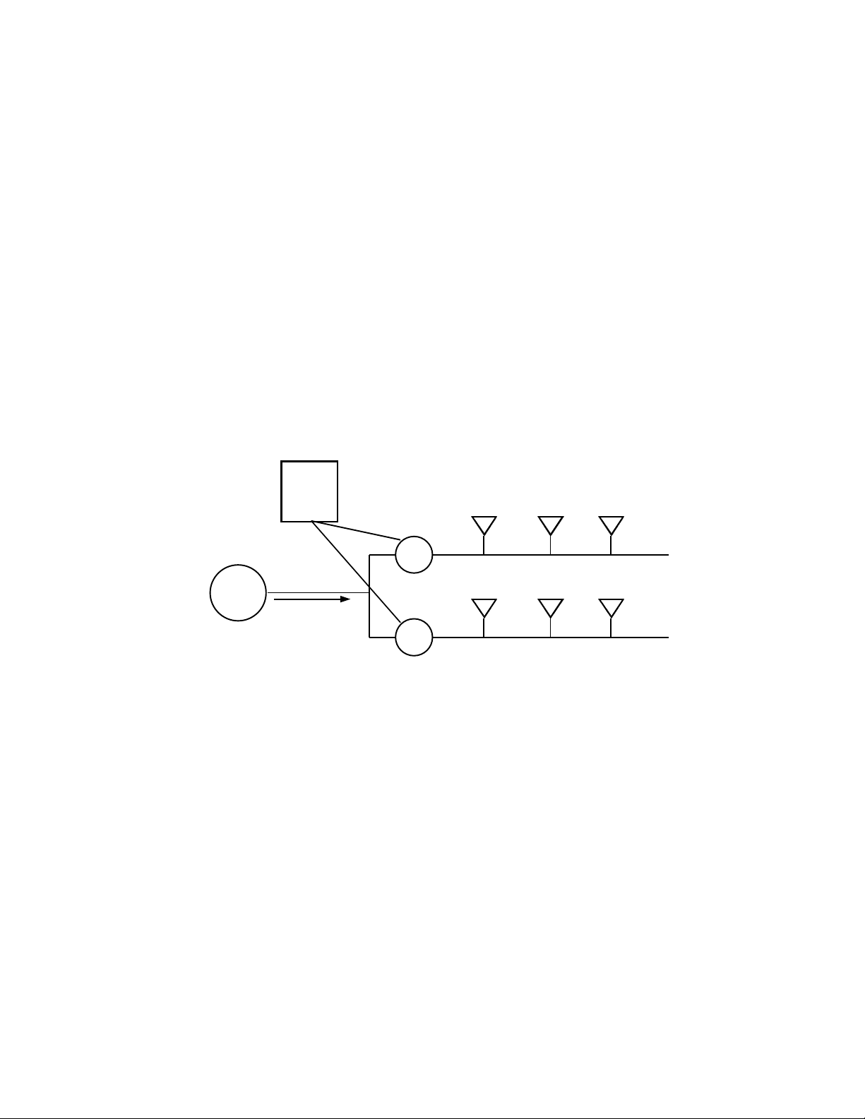
CONTROLLER
SPRINKLERS
VALVE
SHUT
OFF
INCOMING
VALVE
BASIC SYSTEM COMPONENTS
SPRINKLERS
Why are several valves needed? All systems are limited by a combination of the pressure of the water (psi) and the number of gallons per minute (gpm) available. Each
sprinkler uses a certain number of gallons per minute of water. This release of water
through the nozzle reduces water pressure to a certain degree while the system is
working. For maximum performance, each zone is controlled by one valve and is set
up with the proper amount of sprinklers so that the psi and gpm capacity of the system
is not exceeded. The purpose of this information is to address questions and problems
related to zone valves.
2
Page 3
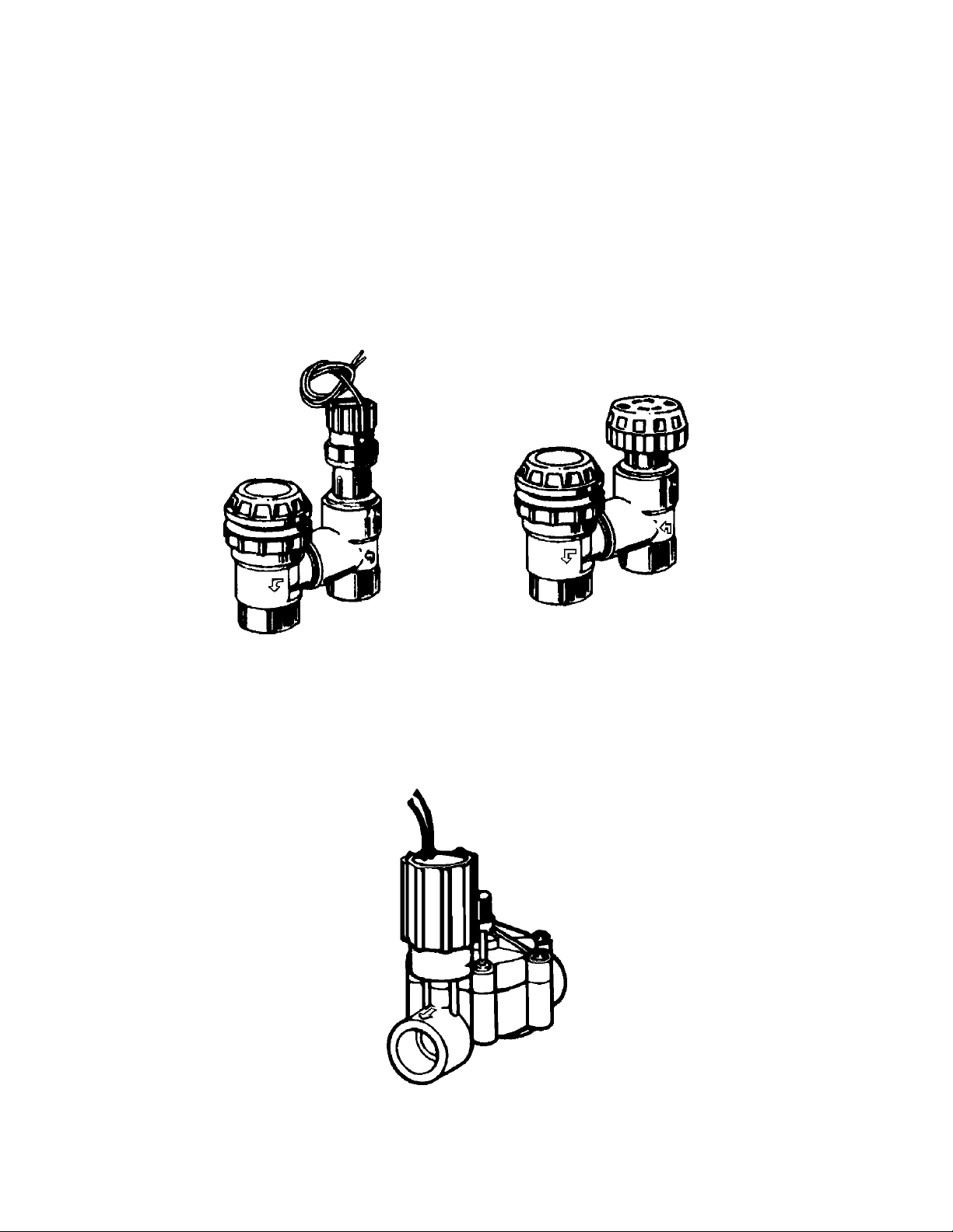
Types of Zone Valves
There are two basic types of zone valves commonly available. Anti-siphon valves
have a built-in backflow device to prevent possibly contaminated water from flowing
backward into the household supply. If approved by your local codes, these types of
valves provide inexpensive backflow protection. Anti-siphon valves must be installed
at least 6" above the highest sprinkler head on the line in order for the backflow device to work properly. Both automatic and manual versions are available.
APAS-100-P
APAS-075-P
PAS-100
PAS-075
The second type of valve is an "in-line" valve. It is installed below ground, preferably
in a valve box, for ease of maintenance. A separate backflow preventer is required for
backflow protection. In-line valves are automatic valves.
CP-075
CP-100
3
Page 4
Anti-Siphon Valves
Anti-siphon valves are an inexpensive choice and easy to install and maintain. The
built-in anti-siphon backflow device prevents potential contamination of household water supplies from fertilizers and other toxic chemicals which may enter the system.
Check your local codes for the types of backflow protection required in your area.
Electric models are simple to hook up to a timer for automatic watering. They are best
suited to plans where there is not more than a slight rise in elevation, and fairly clean
source water.
Caution: This valve is designed as a zone valve and as such may suffer severe damage if installed where constant pressure is placed on the outlet (sprinkler) side of the
valve. The manual version is not suitable for use in a continuous open position as a
main shutoff valve or as a means of inexpensive backflow prevention for an entire system; nor are the automatic models to be used as a master valve where other valves
will be installed downstream.
(Note: A master valve is an electric valve that is automatically activated to open and
allow the flow of water through, only when the zone valves downstream are activated.)
Automatic Anti-Siphon control
valves APAS-075-P/APAS-100-P
Install valves
at least 6”
above
the highest
sprinkler
PVC Pipe
Shutoff
To Sprinklers
Connecting pipe
from water source
Typical installation
using PVC pipe and
fittings
4
Page 5
In-Line Valves
In-line valves, installed below ground level, are suitable for sites with all types of elevation changes. Because of their protected location, in-line valves are less likely to be
tampered with by children or vandals, and less likely to incur freeze damage than
above ground models. In-line valves do not afford backflow protection.
In situations where the water is pumped from a lake, well, ditch, or other "dirty" water
source, sand and other debris should be filtered from the line through a filter with a
100 mesh screen. If water supply is also used as a drinking water source, a separate
backflow prevention device is required to prevent potential contamination should fertilizers or toxic chemicals in the water be siphoned backwards through the lines.
If your water is supplied by a municipal water system, check with your local Rain Bird
dealer or plumbing supplier for the type of backflow prevention device required in your
area. For specific information about backflow and the types of backflow prevention devices available, please call our toll-free number. 1-800-RAIN-BIRD, and request a
"Backflow Prevention Handbook."
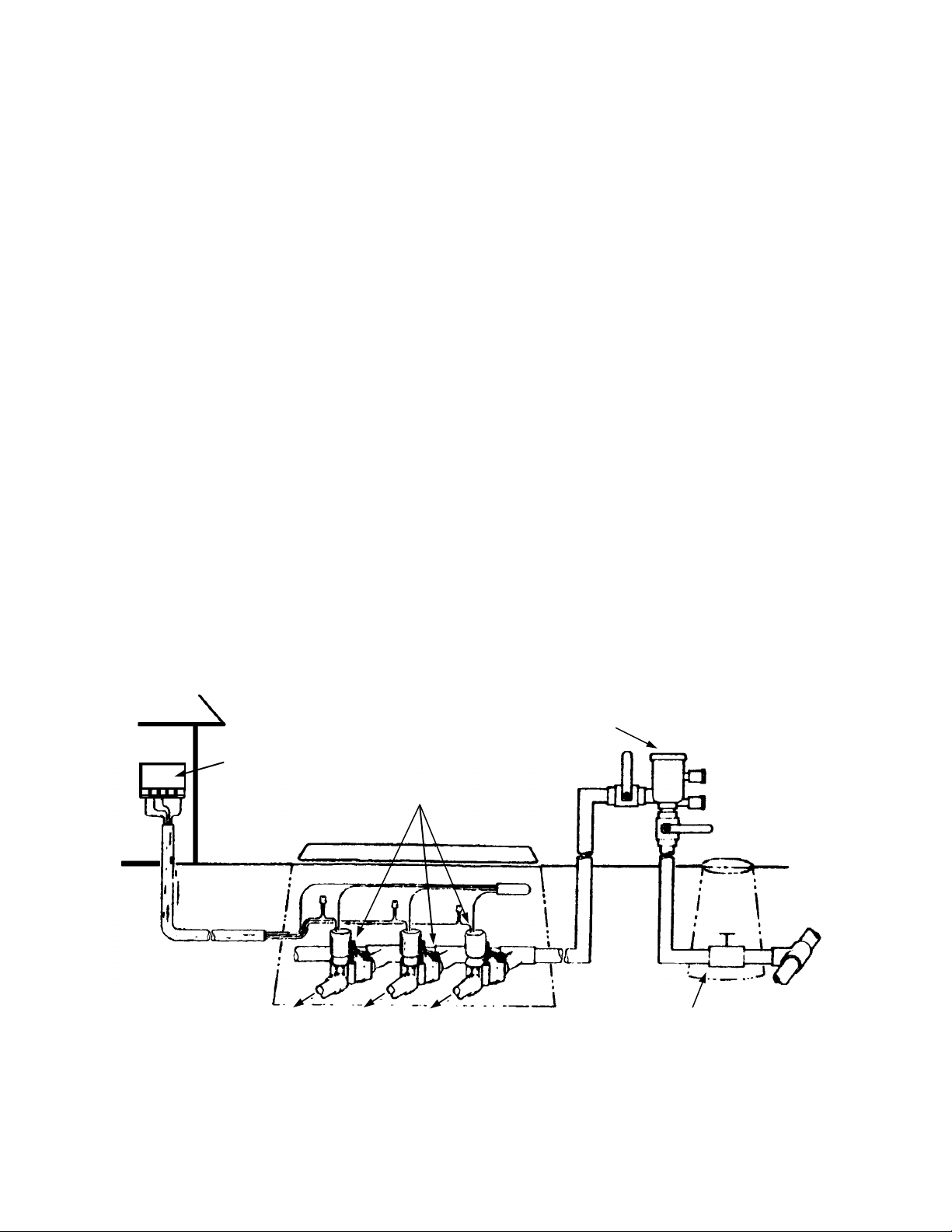
In-line valves are installed below ground, protected by a valve box. An in-line valve is
also suitable for use as a master valve.
CONTROLLER
PVB VALVE
VALVES
Service
Line
from
Street
SHUTOFF
TO
SPRINKLERS
5
Page 6

Tips On New Installations
Tapping Into Your Water Source
Turn off the water at the meter. Cut into your household service line and install a brass
slip-type compression tee, after the meter. The cut can be done anywhere on the line,
depending on the layout of your system and the location of your first manifold. Unless
unregulated static pressure is over 80 psi, tap into the line before the household pressure regulator. In freezing climates, you will probably be tapping into your source inside a basement.
Next, install a gate or ball valve to act as your system shutoff valve. House the valve
in a valve box for easy access in below ground situations. Once this valve is installed
and tested, the valve at the meter may be left open for water usage inside the house.
In freezing climates, your next step will be to install a manual drain valve so that the
water can be drained from the pipes between the zone valves and the shut-off valve.
Install Schedule 40 PVC, thick-walled pipe up to the valves. In basement installations,
you will need to drill a hole through the wall to direct the pipe out to the valves. For
convenience in "blowing out" the system for winter, access to the line by means of a
tee with a capped 1" riser may be installed at this point.
If a backflow preventer is to be used, install it outside at the proper height.
Service to
House
FLUSH, FLUSH, FLUSH. . .Turn on the water at the shutoff valve and flush the pipes
free of dirt.
Meter in House
Compression
Tee
Shutoff
Valve
Shutoff
Valve
Water
Meter
Slope Downward
for Drainage
Shutoff
Valve
Drain
Cap
To
Control
Valves
Service
Line
from
Street
Service
Line to
House
To
Control
Valves
Meter in Yard
Compression
Shutoff
Valve
Tee
Water
Meter
Service
Line
from
Street
6
Page 7

Installing the Manifold
If you are installing a new valve manifold, keep in mind that the location should be
easily accessible for maintenance. Locate the manifold where you are not likely to be
sprayed by the sprinklers when turning the system on manually. On larger systems,
separate manifolds may be required for the front and back yards. It is a good idea to
keep a plan showing where all in-ground valves and pipes have been installed.
Be sure to flush the line coming up to the manifold, before installing the valves. Test
and flush each line before sprinklers are attached. Most valves have a flush mode
which allows a little extra water through the valve to clean it out.
To Flush:
Turn Solenoid (Manual on/Off)
Hold Flow Control
Turn black SOLENOID counterclockwise (do not turn gray ring) until a small amount of water discharges
between SOLENOID and FLOW CONTROL ring.
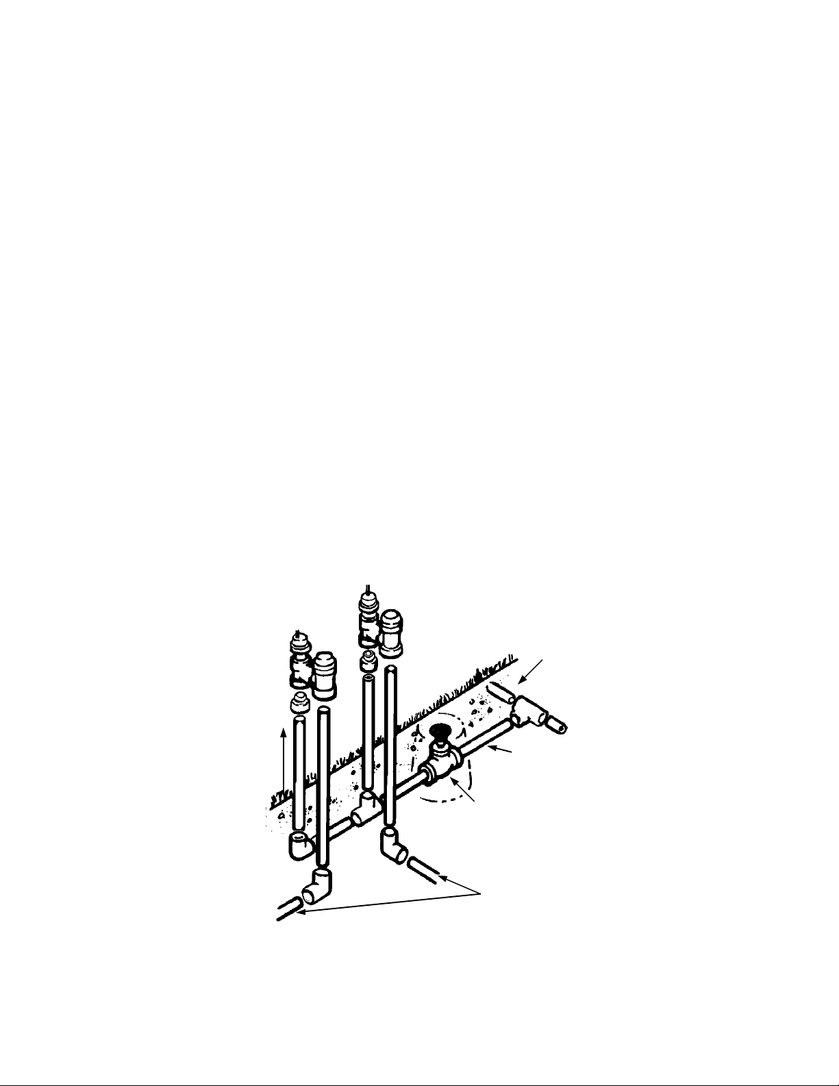
Anti-Siphon Valves Grouped Above Ground
Connecting pipe and fittings to be
the same size as the largest control valve in the group
Connecting pipe
from water source
Install valves
at least 6”
the highest
sprinkler
Typical installation
using PVC pipe and
fittings
above
To Sprinklers
PVC Pipe
To backyard
control valves
7
Page 8

To Flush:
Solenoid
Bleed Knob
(Manual Bleed)
(Manual on/off)
Bonnet
Body
Turn bleed knob 1 full turn counterclockwise and allow water to spray out for 10-15 seconds; turn back
to clockwise position.
Automatic In-Line
control valves
CP-075 for 3/4” pipe
CP-100 for 1” pipe
PVC Pipe
To other
valves
To Sprinklers
Connecting pipe
from water source
Typical Installation
using PVC pipe
and fittings where no
backflow prevention is
required
Installing the Manifold (Continued)
Tip: Partially assembling the manifold ahead of time will make the job easier. Be sure
that the valve is installed horizontally according to the arrows printed on the body for
the direction of flow. Valve operation may be erratic and valve warranty is void if installed backward or in a vertical position. Call our toll-free Technical Services Hotline
for any questions on system installation: 1-800-RAIN-BIRD.
CAUTION: Do not use plumber's pipe dope on valve threads when installing. Chemicals in the pipe dope may react with the plastic in the valve body causing the valve to
weaken and crack at the threads. Three wraps of Teflon tape should be sufficient to
create a leak-proof seal.
How to Operate
Several models of Rain Bird 24 Volt valves are available for home use. Minimum current requirements for opening the smaller valves is .30 amps and for holding the valve
open is .19 amps. Larger valve models have slightly higher requirements. All Rain Bird
valves are designed to work with Rain Bird timers and other timers that have a power
output sufficient to activate the valve. Your Rain Bird valve offers some simple features you should be familiar with. Note: Some valves have only part of these features.
See the diagram above and on the previous page for information on flushing the
valves.
a. Flow control -
b. Manual bleed -
Regulates the amount of water passing through the valve. (Not
available on all models.)
Turns the valve on manually by "bleeding" water off of the diaphragm. External bleed models have a knob or screw to turn
and the water sprays out of the top of the valve. Internal bleed
models have a open/close knob or require a 1/4 turn of solenoid
and water bleeds off inside the valve.
c. Manual On/Off -
Turn solenoid 1/
ally.
turn counterclockwise to turn valve on manu-
4
8
Page 9

Troubleshooting
How the Valve Works
It is easier to troubleshoot valves if you know a little about how the valve works. When
an electrical impulse is transmitted to the solenoid (black cylinder with wires), an electromagnetic field causes a small metal plunger in the solenoid to move upward. When
the plunger moves upward, a small hole (port) in the valve is uncovered. Water in the
chamber above the closing mechanism (either diaphragm or piston) flows through the
port and out of the valve, relieving water pressure needed to hold the valve closed. At
this point, the pressure of the incoming flow of water is now greater than the pressure
in the chamber above the piston/diaphragm, and the force of the water pushing up underneath the piston/diaphragm opens the valve.
When the solenoid is de-energized, the plunger moves down, closing the small port.
Water flowing through a small hole in the closing mechanism refills the chamber
above the piston/ diaphragm and builds up pressure. The increased pressure forces
the piston/diaphragm downward, thus closing the valve. All valves have a range of
pressure and water flow that must be maintained in order to work properly.
Now that you have an idea of the way the valves work. you can see why sufficient
pressure and flow are important. If a problem does occur, it is also very important to
ensure that the small internal ports are not blocked by debris. Adequate flushing is the
key to success in a new installation.
Diaphragm
Moves UpValve Open
How a diaphragm valve opens and closes.
9
Diaphragm
Moves DownValve Closed
Page 10

TROUBLESHOOTING GUIDE
1. For any problem, check the
basics first.
SYMPTOM CAUSE DIAPHRAGM VALVE REMEDY
2. Valve won't turn on with
timer.
A. Is timer plugged in and properly programmed?
B. Is master shut off valve open?
C. Is flow control on valve in an "open" or "flow" position? Not all models have this feature. Check the instructions that came with your
valve, or see "How to Operate" section of this packet.
D. Are water pressure and flow rate adequate for your particular valve model? (Check the instructions that came with the valve or call us
toll free at 1-800-RAIN-BIRD for the requirements of your particular Rain Bird valve model.) If your pressure is too low,. Investigate these
causes:
• Pressure drain from washing machines, showers, etc. or broken pipe,
• Master shutoff valve not fully open,
• Blockage in main supply line; to repair, cut main line, flush line, and repair cut;
• Too many heads on line; redesign system layout to reduce the number of heads operating at once.
E. Is valve in "Manual Off" position? See "How to Operate" section of this packet.
F. If your system is supplied by a pump, is it working?
PISTON-TYPE VALVE REMEDY
A. Check the Basics as in No. 1
above.
(See Valve Disassembly Procedure A)
• If all basics check out, see if the valve will
work manually. On some models you will
need to turn the solenoid 1/4 turn counterclockwise. On other models, turn the screw
in the center of the bonnet (water should
spray out of the top of the valve temporarily). Check your valve operating instructions
or refer to section entitled "How to Operate," in this packet of information. If the
valve works manually, go on to step 2-B. If
the valve doesn't work, go on to step 2-D.
(See Valve Disassembly Procedure B)
• If all basics check out, see if the valve will work
manually by holding onto the gray flow control ring
and turning the solenoid 1/4 turn counter-clockwise.
If the valve works manually, go on to step 2-B. If the
valve doesn't work, go on to step 2-D.
B. No power between timer and
valves.
C. Solenoid burned out or clogged. • The solenoid should make a distinct
D. Valve opening mechanism dam-
aged or clogged with debris. Bleed
ports clogged.
• Check by pressing the "Manual Start"
button of the timer and advance to the
desired station. Attach a circuit tester
(voltmeter) to the common terminal and the
station terminal of the timer. If you do not
get a 24-27 volt reading, the problem is in
the timer.
• Check for shorted or broken wiring. Follow
directions as above, except attach voltmeter
to common wire and station wire nearest
valve. If you do not receive a 24-27 volt
reading, replace or repair wiring.
"click" when activated. If timer and wiring
check out, try unscrewing the solenoid and
swapping it with a nearby valve of the same
model. Using the "Manual Start" on your
timer, check the station again to see if the
borrowed solenoid activates the valve. If so.
replace solenoid. If not check 2-D.
• See if you can flush debris from the valve
by using the flush mode. If not, turn off the
water, disassemble, inspect and clean the
valve (See Valve Disassembly Procedure
A). Pay particular attention to cleaning the
small bleed ports underneath the solenoid
and on the surface of the diaphragm. Check
to see that the diaphragm is not torn damaged. Replace diaphragm if damaged. If
water is particularly dirty, install a 100 mesh
or finer filter before the valve to prevent
future grit build-up.
• See recommendations at left for diaphragm valve.
• See recommendations at left for diaphragm valve.
• See recommendations at left for diaphragm valve.
• Turn off the water. Remove the actuator and examine piston (See Valve Disassembly Procedure B).
Remove dirt and deposits. If removing and cleaning
the piston does not or help, replace with the PRK100 piston replacement kit. If the problem is continual, install a 150 mesh or finer filter before the valve
to prevent future grit build-up,
E. Valve installed backwards • Reinstall valve so that water flow is the
same direction as arrows embossed on
valve.
10
• See recommendations at left for diaphragm valve.
Page 11

TROUBLESHOOTING GUIDE
SYMPTOM CAUSE DIAPHRAGM VALVE REMEDY
3. Valve won't turn off with timer. A. When the valve won't turn off
4. Water leaks out at sprinkler
heads when station is off.
with the timer, the foremost goal is
to stop the flow of water. When this
is accomplished, check steps B
through D for trouble-shooting
procedure.
B. Solenoid burned out or plunger
clogged.
C. Valve closing mechanism stuck
in open position due to debris or
damage.
D. Damaged or misaligned parts
allow water to leak from valve.
E. Valve set in "Manual On" mode. • Depending on the model, you will need to
A. Closing mechanism dirty or
damaged and does not seat properly.
B. Valve not fully in "Manual Off"
mode.
C. Solenoid burned out or obstructed.
D. Low head drainage. • It is normal for water to temporarily con-
(See Valve Disassembly Procedure A)
• Put timer in auto/off (Rain Shutoff) mode. If
watering continues. . .
• Unplug timer. If this stops the watering, the
problem is probably in the timer. If watering
continues. . .
• Turn flow control knob (if there is one) to
lowest flow position. If this does not shut off
the flow completely. . .
• Turn off manual main shut off valve to
sprinkler system.
• Check solenoid as in 2-C. Check for dirt
impeding the movement of the plunger. To
do this, turn off the water and remove
power to the solenoid. Unscrew the
solenoid. Sometimes the plunger inside the
solenoid can become stuck in the upward
position due to dirt in the solenoid. Run water
into the solenoid to dislodge dirt. Push a
piece of wire into the small hole in the retainer at the bottom of the solenoid to see if
the plunger inside will move up and down
freely. If not. replace the solenoid.
• See Valve Disassembling Procedure A.
Check small ports for blockage by debris;
rinse and inspect diaphragm and diaphragm
seat for dirt or damage. Replace diaphragm
if damaged.
• Check valve body and bonnet for cracks.
Check integrity of seal between body and
bonnet and solenoid and bonnet. Repair or
replace parts as necessary to stop leak.
be sure the solenoid is tightened into the full
clockwise position ("Manual Off") or turn the
bleed screw or knob on top of the valve
clockwise to tighten. See section entitled
"How to Operate."
• See Valve Disassembly Procedure A.
Check small ports for blockage by debris;
rinse and inspect diaphragm and diaphragm
seat for dirt or damage. Replace diaphragm
or valve body if damaged.
• See 3-E above. • See 3-E above
• Turn off water. Remove solenoid. Check for
twisting or damage to solenoid O-ring. Check
solenoid plunger as in 3-B above. Rinse
bottom of solenoid and seating surface inside valve. Replace solenoid if damaged.
tinue to drain from the piping through the
lowest head on the line. The longer the piping, and the lower the slope of the pipe, the
longer this will take.
PISTON-TYPE VALVE REMEDY
(See Valve Disassembly Procedure B)
• See recommendations at left for diaphragm valve.
• See recommendations at left for diaphragm valve.
• Turn gray flow control ring on valve clockwise
until resistance is felt. This is the lowest flow position. If more than one valve is affected or if turning
the flow control does not shut off the flow completely...
• See recommendations at left for diaphragm valve.
• See recommendations at left for diaphragm valve.
• Remove piston and check for debris that may be
restricting movement (See Valve Disassembling
Procedure B). If piston is damaged replace with
PRK-100 piston replacement kit.
• Check for crack in actuator or bent o-rings. Replace actuator or o-rings to stop leak.
• Hold gray flow control ring and turn solenoid
clockwise until resistance is felt.
• See Valve Disassembly Procedure B. If thoroughly cleaning the piston and housing does not
help, replace piston with PRK-100 piston replacement kit.
• See recommendations at left for diaphragm valve.
• Same for all types of valves. See recommendations at left for diaphragm valve
11
Page 12

TROUBLESHOOTING GUIDE
SYMPTOM CAUSE DIAPHRAGM VALVE REMEDY
4. Water leaks out at sprinkler
head when station is off.
(Continued)
5. Valve won't turn off manually. A. Valve in "Manual On" mode.
6. Valve won't turn on manually. A. Flow control in closed position.
7. Water leaks out at valve. A. Leaking round pipe connections. • Tighten connections (use teflon tape only). • See recommendations at left for di-
- C. Leaking between bonnet and body. • Check that diaphragm washer is properly in
8. Valve slams on/off (water ham-
mer)
9. Water runs continuously when
valve is not activated; shuts off
when valve is activated.
D. Low head drainage. (Continued) Stop watering on the soggy zone for two days.
B. Valve closing mechanism stuck in
open position.
C. Solenoid energized
B. Valve opening mechanism blocked
by debris.
C. Valve in "Manual Off" mode.
B. Leaking around actuator assembly. • Not applicable. • Tighten actuator to body (See Valve Dis-
D. Leaking under anti-siphon cap.
(Anti-siphon models only).
A. Excessive water pressure. • Install pressure regulator on line before valves
B. Valve closing/opening mechanism
worn.
C. Air bubble in line • Shut off water at main shut off valve and drain
D. Valve too small for amount of flow. • Replace with larger valve • Not applicable
A. Valve installed backwards. • Reinstall valve according to arrows on valve
(See Valve Disassembly Procedure A)
Check the lowest head on the line.
If area is very wet or a small amount of water
drips from sprinkler, see 4-A and 4-B above. If
area around sprinkler has dried out somewhat,
the problem is probably due to drainage from
the piping.
• See 3-E above.
• See 3-C above.
• Stop power to valve.
• See I-C above.
• See 2-D above.
• See 2-A above.
place. Tighten bonnet screws.
• Not applicable. • Float under cap is not moving freely due
• Not applicable • Valves not installed 6" higher than highest
• Not applicable • Insufficient water pressure (See I-D)
• Not applicable • Vacuum breaker cap or valve body
to reduce pressure.
• Replace diaphragm with model number appropriate for your valve. Call our Technical Service
hotline for assistance in identifying valve or part
numbers. 1-800-RAIN-BIRD
the line to release air bubble. Slowly refill the
line.
depicting direction of flow.
PISTON-TYPE VALVE REMEDY
(See Valve Disassembly Procedure B)
• See 3-E above.
• See 3-C above.
• Stop power to valve
• Turn gray ring counterclockwise to increase flow.
• See 2-D above.
• See 2-A above.
aphragm valve.
assembly Procedure B) Be sure O-ring seal
is in place. Do not use pipe dope or teflon
tape or tighten with such force as to crack
plastic valve body.
• Not applicable.
to debris. Turn off water and unscrew cap.
Clean out area around float and replace
float and cap.
sprinkler head. Raise position of valve or
redesign system.
cracked. Replace as necessary.
• See recommendations at left for diaphragm valve.
• Replace piston with PRK-100 piston replacement kit.
• See recommendations at left for diaphragm valve.
• Not applicable.
12
Page 13

Disassembling the valve for cleaning or part replacement
— Disassembly Procedure A
To inspect the inside of the valve for cleaning or replacement of the diaphragm
use the following procedure:
1. Shut off the water at the master shut off valve.
2. Unscrew all bonnet screws. On some models, the bleed screw and/or flow control
knob will also need to be removed.
3. Remove bonnet assembly to expose the spring, diaphragm, and rubber gasket (if
any) and filter (if any). Remove and inspect the spring, diaphragm, and rubber gasket for wear or damage. Inspect the diaphragm for clog or a tear in the small hole
on its surface.
4. Inspect the valve body for dirt on the diaphragm seat.
5. Inspect the bonnet for dirt clogging the small bleed port near the solenoid.
6. Rinse dirt off if necessary, or use a wire to gently dislodge dirt from the bleed port.
7. Install new diaphragm if necessary. Do not forget to replace the spring. Some new
replacement diaphragms are an all-in-one design and do not have a separate rubber gasket to install. Be sure that the holes line up.
8. Press the bonnet firmly back in place. Replace the screws and tighten. Pressure
test the valve to assure that all of the screws are tight enough to prevent any water
leakage between the valve body and bonnet.
To replace the solenoid:
1. Unscrew the solenoid.
2. Check for debris clogging the small port where the solenoid seats.
3. Rinse off the solenoid to remove debris.
4. Check condition of solenoid O-ring.
5. Replace solenoid if necessary with part number applicable to your particular
model.
Model Solenoid P/N Diaphragm P/N
CP-075 or-100 208484 209391
EV-100 EV-100F 407200 407303
13
Page 14

CP-075
CP-100
VALVE PARTS
SOLENOID
BONNET SCREWS
BLEED PORT
BLEED SCREW
BONNET
DIAPHRAGM KIT
•Spring
•Diaphragm*
•Body Seal*
*May be combined as
BLEED PORT
one piece.
VALVE BODY
If you need further assistance, or other advice on installation,
contact our customer service team at 1-800-RAIN-BIRD.
CP-075-P
CP-100-P
EV-100
INSURE QUALITY - USE ONLY GENUINE RAIN BIRD PARTS
14
Page 15

Disassembling the valve for cleaning or part replacement
— Disassembly Procedure B
A removable actuator makes piston-type valves easy to access for maintenance.
Should you need to clean the valve or replace a part, the actuator is removable following these procedures:
1. Shut off the water at the master shut off valve.
2. Using a pair of adjustable pliers clamped in the area of the valve indicated in the
illustration (next page), unscrew the actuator counterclockwise.
3. To inspect the piston seals or replace the piston, gently pull piston from the bottom
to pull it out of valve.
4. To remove solenoid, hold gray flow ring and twist counter-clockwise to unscrew.
To reassemble the valve actuator assembly, screw it into the valve body in a clockwise direction until the actuator body contacts the valve body. Caution: Do no over
tighten as this may cause damage to the actuator. Do not use any pipe dope or tape
on the actuator threads. The bleed ports (holes) just above the threads can become
clogged and prevent operation.
Two types of Repair kits are available, the SRK-1 Solenoid Replacement Kit and the
PRK-100 Piston Replacement Kit.
Ref. Part Description Part No.
1 Solenoid Assembly (SRK-1) B40602
2 O-Ring
3 Piston Repair Kit (Santoprene) (PRK-100) B40642
4 Piston
5 Piston Spring
Piston Retainer
Piston Sleeve
6 Filter
7 Upper Bonnet O-Ring
8 Lower Bonnet O-Ring
9 Cap, Cover & Piston Assembly 210067
10 Cap & Cover Assembly 203661
11 Gasket
12 Piston Vacuum Breaker
13 Sealing Washer
14 Body
Please see the parts diagram on the next page.
15
Page 16

Parts and Repair Information
A variety of parts and parts assemblies are available for Rain Bird valves. If your local
Rain Bird dealer does not carry the part you need, ask if it can be ordered, or call our
toll free Technical Services hotline for dealer referral or factory direct ordering information. If you are unsure of the model you have or need help in identifying or finding a
part, the Technicians on our toll-free line are eager to assist you. A parts breakdown
on your particular model is available upon request.
If you have any questions about the information in this packet or about any Rain Bird
products, call us toll free for fast and knowledgeable service at: 1-800-RAIN-BIRD.
Customer Support Center: 6640 S. Bonney Ave., Tucson, AZ 85706
FAX: (520) 434-6289
In-Line Valves
(Discontinued)
AGV-075-P
AGV-100-P
PAS-100
Manual
Anti-Siphon
Valve
Anti-Siphon Valve
With Backflow Prevention
APAS-075-P
APAS-100-P
1
2
(Inside)
Actuator
(See inset)
Actuator AVA-100-P
Solenoid Replacement Kit
Use pliers
here to remove
Piston Replacement Kit
SRK-1
PRK-100
O-ring
Piston seal
(Inspect for
wear or
5
4
6
7
10
8
11
12
3
13
14
9
INSURE QUALITY - USE ONLY GENUINE RAIN BIRD PARTS
16
 Loading...