

Rain Bird PT5002 User Manual

Industrial Flow Computer
PT5002 Flow Monitor
User Manual

Industrial Flow Computer, PT5002 Flow Monitor
CONTENTS
Scope of This Manual � � � � � � � � � � � � � � � � � � � � � � � � � � � � � � � � � � � � � � � � � � � � � 4
Unpacking and Inspection � � � � � � � � � � � � � � � � � � � � � � � � � � � � � � � � � � � � � � � � � 4
Safety Considerations� � � � � � � � � � � � � � � � � � � � � � � � � � � � � � � � � � � � � � � � � � � � � 4
Terminology and Symbols� � � � � � � � � � � � � � � � � � � � � � � � � � � � � � � � � � � � � � � 4
Safety Instructions � � � � � � � � � � � � � � � � � � � � � � � � � � � � � � � � � � � � � � � � � � � 5
Safety Rules and Precautionary Measures � � � � � � � � � � � � � � � � � � � � � � � � � � � � � 5
Description � � � � � � � � � � � � � � � � � � � � � � � � � � � � � � � � � � � � � � � � � � � � � � � � � � � 6
Functions and Features � � � � � � � � � � � � � � � � � � � � � � � � � � � � � � � � � � � � � � � � 6
Flow Meter Input � � � � � � � � � � � � � � � � � � � � � � � � � � � � � � � � � � � � � � � � � � � � 6
Digital Inputs � � � � � � � � � � � � � � � � � � � � � � � � � � � � � � � � � � � � � � � � � � � � � � � 6
Relay Control Outputs � � � � � � � � � � � � � � � � � � � � � � � � � � � � � � � � � � � � � � � � � 6
Power Supply� � � � � � � � � � � � � � � � � � � � � � � � � � � � � � � � � � � � � � � � � � � � � � � 7
Conguring the Unit � � � � � � � � � � � � � � � � � � � � � � � � � � � � � � � � � � � � � � � � � � 7
Display Information� � � � � � � � � � � � � � � � � � � � � � � � � � � � � � � � � � � � � � � � � � � 7
Installing the PT5002 � � � � � � � � � � � � � � � � � � � � � � � � � � � � � � � � � � � � � � � � � � � � � 7
Mounting Options� � � � � � � � � � � � � � � � � � � � � � � � � � � � � � � � � � � � � � � � � � � � 8
Installation Overview � � � � � � � � � � � � � � � � � � � � � � � � � � � � � � � � � � � � � � � � � � � � 11
Wiring the PT5002 � � � � � � � � � � � � � � � � � � � � � � � � � � � � � � � � � � � � � � � � � � � � � � 16
Terminal Connector Descriptions � � � � � � � � � � � � � � � � � � � � � � � � � � � � � � � � � 17
Operator Interface� � � � � � � � � � � � � � � � � � � � � � � � � � � � � � � � � � � � � � � � � � � � � � 22
Keypad and Soft Keys � � � � � � � � � � � � � � � � � � � � � � � � � � � � � � � � � � � � � � � � 22
Scrolling � � � � � � � � � � � � � � � � � � � � � � � � � � � � � � � � � � � � � � � � � � � � � � � � � 22
Control Panel Keys � � � � � � � � � � � � � � � � � � � � � � � � � � � � � � � � � � � � � � � � � � 22
Icon Functionality � � � � � � � � � � � � � � � � � � � � � � � � � � � � � � � � � � � � � � � � � � � 23
Numeric Editing � � � � � � � � � � � � � � � � � � � � � � � � � � � � � � � � � � � � � � � � � � � � 24
Alpha-Numeric Editing� � � � � � � � � � � � � � � � � � � � � � � � � � � � � � � � � � � � � � � � 24
Selection/Enumeration Editing � � � � � � � � � � � � � � � � � � � � � � � � � � � � � � � � � � 25
Conrmation Screen � � � � � � � � � � � � � � � � � � � � � � � � � � � � � � � � � � � � � � � � � 25
Navigating the Menus � � � � � � � � � � � � � � � � � � � � � � � � � � � � � � � � � � � � � � � � 26
Menu Structure � � � � � � � � � � � � � � � � � � � � � � � � � � � � � � � � � � � � � � � � � � � � 27
Info/Sensor Data � � � � � � � � � � � � � � � � � � � � � � � � � � � � � � � � � � � � � � � � � � � � � � � 28
System Information � � � � � � � � � � � � � � � � � � � � � � � � � � � � � � � � � � � � � � � � � � � � � 29
Basic Setup � � � � � � � � � � � � � � � � � � � � � � � � � � � � � � � � � � � � � � � � � � � � � � � � � � 30
Display � � � � � � � � � � � � � � � � � � � � � � � � � � � � � � � � � � � � � � � � � � � � � � � � � � 30
Resets � � � � � � � � � � � � � � � � � � � � � � � � � � � � � � � � � � � � � � � � � � � � � � � � � � 30
Passcode Setup � � � � � � � � � � � � � � � � � � � � � � � � � � � � � � � � � � � � � � � � � � � � 31
Page 2 June 2020

User Manual
Units � � � � � � � � � � � � � � � � � � � � � � � � � � � � � � � � � � � � � � � � � � � � � � � � � � � 32
Advanced Setup � � � � � � � � � � � � � � � � � � � � � � � � � � � � � � � � � � � � � � � � � � � � � � � 34
Conguring a Flow Meter � � � � � � � � � � � � � � � � � � � � � � � � � � � � � � � � � � � � � � 34
Conguring Outputs � � � � � � � � � � � � � � � � � � � � � � � � � � � � � � � � � � � � � � � � � 35
Conguring Digital I/O � � � � � � � � � � � � � � � � � � � � � � � � � � � � � � � � � � � � � � � � 38
Conguring BACnet Communications � � � � � � � � � � � � � � � � � � � � � � � � � � � � � � 39
BACnet Map � � � � � � � � � � � � � � � � � � � � � � � � � � � � � � � � � � � � � � � � � � � � � � 39
Troubleshooting � � � � � � � � � � � � � � � � � � � � � � � � � � � � � � � � � � � � � � � � � � � � � � � 40
Specications � � � � � � � � � � � � � � � � � � � � � � � � � � � � � � � � � � � � � � � � � � � � � � � � � 42
Standards and Certications � � � � � � � � � � � � � � � � � � � � � � � � � � � � � � � � � � � � � � � 45
Agency Approval/Standards � � � � � � � � � � � � � � � � � � � � � � � � � � � � � � � � � � � � 45
EMI/EMC Compliance� � � � � � � � � � � � � � � � � � � � � � � � � � � � � � � � � � � � � � � � � 45
Enclosure Protection � � � � � � � � � � � � � � � � � � � � � � � � � � � � � � � � � � � � � � � � � 45
APPENDIX A � � � � � � � � � � � � � � � � � � � � � � � � � � � � � � � � � � � � � � � � � � � � � � � � � � 46
For Rain Bird Tee Type Flow Sensors and Anemometer� � � � � � � � � � � � � � � � � � � � 46
APPENDIX B � � � � � � � � � � � � � � � � � � � � � � � � � � � � � � � � � � � � � � � � � � � � � � � � � � 47
For Rain Bird Insert Type Flow Sensors� � � � � � � � � � � � � � � � � � � � � � � � � � � � � � 47
Rain Bird’s Professional Customer Satisfaction Policy � � � � � � � � � � � � � � � � � � � � � � � � 52
June 2020
Page 3
Scope of This Manual
SCOPE OF THIS MANUAL
This manual describes how to install and program the PT5002�
MPORTANTI
Read this manual carefully before attempting any installation or operation.
Keep the manual in an accessible location for future reference.
UNPACKING AND INSPECTION
Upon opening the shipping container, visually inspect the product and applicable
accessories for any physical damage such as scratches, loose or broken parts, or
any other sign of damage that may have occurred during shipment�
OTE: N If damage is found, request an inspection by the carrier’s agent within
48 hours of delivery and file a claim with the carrier� A claim for equipment damage
in transit is the sole responsibility of the purchaser�
SAFETY CONSIDERATIONS
Terminology and Symbols
Indicates a hazardous situation, which, if not avoided, will result in death or
serious personal injury�
WARNING
• Operating temperature is 32…130° F (0…55° C) with a maximum humidity
of 85% non-condensing� Always select a mounting location with proper
ventilation and environmental protection�
• Maximum operating altitude: 2000 meters (6561 feet)
• Pollution Degree 2: Only non-conductive pollution occurs except that
occasionally a temporary conductivity caused by condensation is to
be expected
• Over-Voltage Rating: CAT II
Indicates a hazardous situation, which, if not avoided, could result in death or
serious personal injury�
Indicates a hazardous situation, which, if not avoided, could result in minor or
moderate personal injury or damage to property�
Please consult the user manual in all cases where this symbol is used in order
to find out the nature of potential hazards, and any actions which have to be
taken to avoid them�
This symbol signifies that the PT5002 may be powered by a DC power supply�
Acceptable DC input voltage range is: 10…40V DC�
This symbol signifies that the PT5002 may be powered by an AC power
supply� Acceptable AC input voltage range is:
9…28V AC RMS (50…60 Hz)�
Page 4 June 2020

Safety Considerations
Safety Instructions
WARNING
• LIFE SUPPORT APPLICATIONS: THE PT5002 IS NOT DESIGNED FOR USE IN LIFE
SUPPORT APPLIANCES, DEVICES, OR SYSTEMS WHERE MALFUNCTION OF
THE PRODUCT CAN REASONABLY BE EXPECTED TO RESULT IN A PERSONAL
INJURY. CUSTOMERS USING OR SELLING THESE PRODUCTS FOR USE IN SUCH
APPLICATIONS DO SO AT THEIR OWN RISK AND AGREE TO FULLY INDEMNIFY
THE MANUFACTURER AND SUPPLIER FOR ANY DAMAGES RESULTING FROM
SUCH IMPROPER USE OR SALE.
• ELECTROSTATIC DISCHARGE INFLICTS IRREPARABLE DAMAGE TO
ELECTRONICS. BEFORE INSTALLING OR OPENING THE UNIT, INSTALLERS
MUST DISCHARGE THEMSELVES BY TOUCHING A WELL-GROUNDED OBJECT.
• THIS UNIT MUST BE INSTALLED IN ACCORDANCE WITH THE EMC
(ELECTROMAGNETIC COMPATIBILITY) GUIDELINES.
Safety Rules and Precautionary Measures
The manufacturer accepts no responsibility whatsoever if the following safety
rules and precaution instructions and the procedures as described in this manual
are not followed�
• Modifications of the PT5002 implemented without preceding written consent
from the manufacturer will result in the immediate termination of product
liability and warranty period�
• Installation, use, maintenance, and servicing of this equipment must be carried
out by authorized technicians�
• Check the mains voltage and information on the manufacturer’s nameplate
before installing the unit�
• Check all connections, settings and technical specifications of the various
peripheral devices with the PT5002 supplied�
• Never open the enclosure�
• Never touch the electronic components (ESD sensitivity)�
• Never expose the system to heavier conditions than allowed according to the
casing classification (see manufacturer’s nameplate)�
• If the operator detects errors or dangers, or disagrees with the safety
precautions taken, then inform the owner or the principal responsible�
• Adhere to the local labor and safety laws and regulations�
Page 5 June 2020

Description
DESCRIPTION
The PT5002 is a microprocessor-driven device that is designed for flow and wind
speed monitoring� This manual was written for firmware version 1�3�3�683
Functions and Features
This product is designed with a focus on:
• Large display for easy viewing
• Ease-of-use with softkeys and a full numeric keypad
• Ruggedness for its application with a robust enclosure, keypad and
mechanical relays
• Info/Sensor Data Screen—view raw and calculated data, both to and from the
unit, including flow data and output statuses
• User-friendly installation with quality plug-and-play terminals
• A wide range of outputs and functions for a broad fulfillment in
many applications
• User defined relay triggers for flow rates and totals
Flow Meter Input
The PT5002 accepts a passive or active signal output� The input circuit supports
low and high frequency (0�5…3500 Hz) flow meters� A 12V DC exitation terminal is
available for flow meter sensors that require power�
Digital Inputs
The PT5002 control inputs allow the following functions:
• Unlatch Relays
• Reset Totalizers
• Unlatch Relays and Reset Totalizers
Relay Control Outputs
The PT5002 has two independent relay outputs, a mechanical Form C switch and
a solid state form A switch� All control functions are always available by dedicated
relay outputs� Unneeded outputs may be left disconnected or disabled within the
firmware�
Relays in general, can be used for alarm indication or as a totalizing output�
Form-C
• Can be powered directly from mains circuits rated up to 240V�
• Must be powered through circuits that are insulated from mains by at least
basic insulation�
• Connected sources of power need to be limited to 240V AC and fused at 5A
or less�
• Not suitable for connection to external circuits that are insulated from mains by
at least double insulation (SELV)�
Page 6 June 2020

Installing the PT5002
Form A
• Located on TB4 and recommended to use, if configured as a high-rate,
totalizing output�
• Relay energizes (contact closes) with a minimum input current of 3 mA through
the input LED�
• The relay turns off (contact opens) with an input voltage of 0�8V or less�
Power Supply
The power supply used must be isolated from mains by double or reinforced
insulation (for instance, SELV power supply)�
The PT5002 operates on 10…40V DC or 9…28V AC supplied by any suitable
source that also meets the requirement listed above� A pre-wired wall wart power
supply is included with the device, as well as several adapters for different kinds of
power outlets�
A power supply not sourced from the factory must be capable of supplying a
minimum of 8 Watts�
Conguring the Unit
The PT5002 is designed for many types of applications� See “Advanced Setup” on
page34 for instructions on configuring your
PT5002 to your specific requirements�
All information is stored in EEPROM memory and will not be lost in the event of
power failure�
Display Information
The PT5002 has a large transflective LCD with a bright LED backlight that displays
symbols and digits for measuring units, status information and keyword messages�
See “Units” on page32�
INSTALLING THE PT5002
MOUNTING, ELECTRICAL INSTALLATION, STARTUP AND MAINTENANCE OF THIS
INSTRUMENT MAY ONLY BE CARRIED OUT BY TRAINED PERSONNEL AUTHORIZED BY
THE OPERATOR OF THE FACILITY. PERSONNEL MUST READ AND UNDERSTAND THIS
OPERATING MANUAL BEFORE CARRYING OUT ITS INSTRUCTIONS.
THE PT5002 MAY ONLY BE OPERATED BY PERSONNEL WHO ARE AUTHORIZED AND
TRAINED BY THE OPERATOR OF THE FACILITY. OBSERVE ALL INSTRUCTIONS IN THIS
MANUAL.
OBEY ALL SAFETY PRECAUTIONS IN “SAFETY CONSIDERATIONS” ON PAGE4.
Page 7 June 2020
Installing the PT5002
Mounting Options
The PT5002 can be mounted on a wall, shelf or instrumentation panel� Wall-mount
units are shipped in a NEMA 4X enclosure, ready to mount�
Panel-Mount Installations
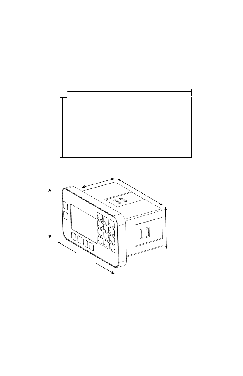
OTE: N Mounting clips can accommodate a maximum panel thickness of 1�5 in� (38�1 mm)�
5.40 in.
(137.16 mm)
2.65 in.
(67.31 mm)
Figure 1: Panel cutout
3.07 in.
(78.00 mm)
Panel Cutout
5.38 in.
(136.65 mm)
3.50 in.
(89.00 mm)
2.54 in.
(64.52 mm)
6.22 in.
(158.00 mm)
Figure 2: Mounting dimensions
To install:
1� Measure and cut a mounting hole to the dimensions shown in Figure 1�
2� Verify that the gasket is secure inside the mounting bezel�
3� Insert the unit through the panel cutout�
4� Secure the unit to the panel with the provided mounting clips (see page 9).
Page 8 June 2020
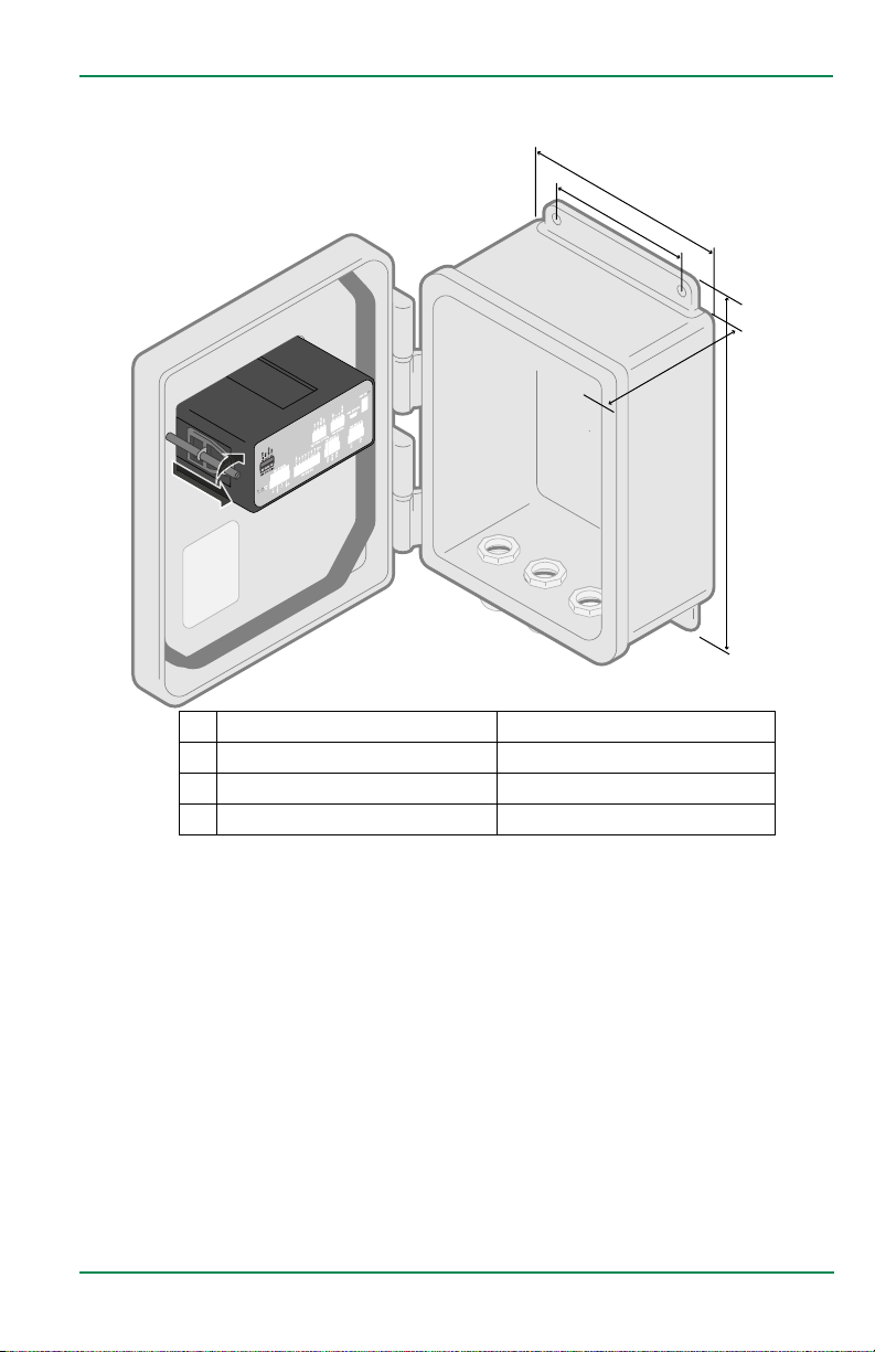
NEMA Installation
Installing the PT5002
A�
B�
C�
D�
A. Width 9�38 in� (238�25 mm)
B. Distance between mounting holes 6�00 in� (152�40 mm)
C. Total depth 4�88 in� (123�95 mm)
D. Height 9�65 in� (245�11 mm)
Wall-Mount Installations
To install the PT5002 cabinet on a wall, secure the enclosure to the wall with four
mounting screws (customer-supplied)�
MOUNTING THE PT5002
When mounting the PT5002 to a Panel, or to the NEMA enclosure, place the
PT5002 through the cabinet's front panel, and hold against the outer surface�
Slide the mounting hardware firmly into the shallow undercut on the left and
right sides of the monitor, pulling away from the panel surface� Firmly tighten the
screw clockwise, to compress the rubber seal against the outer surface� Do not
overtighten�
Page 9 June 2020
Installing the PT5002
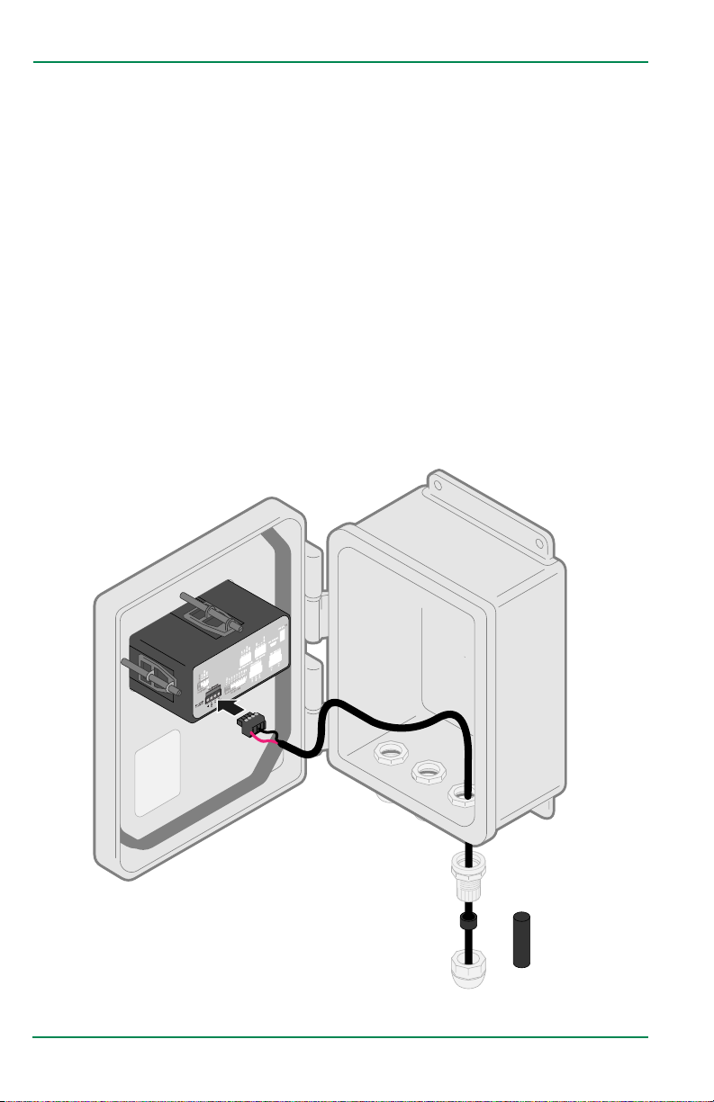
Installation Materials
1� Wire Strippers
2� Wire Cutters
3� Thin blade screwdriver
4� PE-39 #19 AWG Wire (for
Anemometer Instillation)
Wiring Instructions
1� Remove compression nut
2� Remove Rubber bushing and
rubber plug
3� Discard Rubber Plug
4� Thread the wire through the
compression nut, rubber bushing
and housing
5� Install connector (see wiring
instructions p. 16 – 21)
5� 10 AWG Wire
6� #18 AWG Wire
7� Wire Nuts
6� Snap connector into back panel
7� Press rubber bushing into
housing seat
8� Tighten compression nut
until sealed
Connector
Rubber Bushing
Compression Nut
Page 10 June 2020
Rubber Plug
Installation Overview
INSTALLATION OVERVIEW
The PT5002 scales the flow sensor or Anemometer wind sensor output for input
into Maxicom and SiteControl Satellite Controller Systems� It can also be used
with the Anemometer wind sensor for high wind shutdown for ESP-LX Controllers�
When connecting to Flow Sensors or Anemometers, a surge kit may be required to
protect the components� When connecting to various controllers, a decoder may
be required� Please check the following pages in this manual as well as the Tech
Specs for each controller on the Rain Bird website www�rainbird�com�
Transformer
Power
ESP-LXME/ LXMEF
ESP-LXIVM
Flow Sensor
Sensor
Input
LXIVMSEN
Surge
Protection
FSSURGEKIT
Sensor
Decoder
SD210TURF
Anemometer
PT5002
Pulse
Decoder
DECPULLR
Control a Valve
Control a Pump
Start Relay
Maxicom or SiteControl
ESP-SAT Link Satellite
and Maxicom ESP-SITE
ESP-LXD
Maxicom or SiteControl
ESP-SAT Two-Wire
Satellite
Satellite
• PT5002 required for Anemometer use with LXD, LXIVM, and LXME/F
• PT5002 not required for Flow Sensing with LXD, LXIVM, and LXME/F
Page 11 June 2020
Installation Overview
PT5002 T
erminal Connections for Flow Sensor or Anemometer for Maxicom
and SiteControl ESP-SAT Two-Wire Satellite Systems
Anemometer
or
Flow Sensor
Decoder
(DECPULLR)
Power Supply
Maxicom and
SiteControl ESP-
SAT Two-Wire
Satellite Systems
PT5002 Terminal Connections for Flow Sensor or Anemometer for Maxicom
and SiteControl ESP-SAT Link Satellites and Maxicom ESP-SITE Satellite
Systems
Anemometer
or
Flow Sensor
Maxicom and
SiteControl ESP-SAT
Link Satellite and
Maxicom ESP-SITE
Satellite Systems
Power Supply
Page 12 June 2020
Installation Overview
PT5002 T
erminal Connections for Anemometer for 2-Wire Sensor LXD or
LXIVM Controllers
ESP-LXIVM
OR
ESP-LXD
Anemometer
Power Supply
Sensor Input
LXIVMSEN
Sensor Decoder
SD210TURF
ESP-LXMEF with 1 Flow Sensor, 1 Master Valve, and a Pump Start Relay
controlled by a PT5002 Flow Monitor used to control a Booster Pump
ESP-LXME
FSMLXME Flow
Smart Module
Master Valve
Flow Sensor
Power Supply
CST Isoflow
Sharing Relay
PSR Universal
Pump Start
Relay
Power Supply
Page 13 June 2020
Installation Overview
ANEMOMETER Wiring to PT5002 Relay & ESP-LXME/-LXMEF Controller
Anemometer
ESP-LXME/F
Controller
Weather Sensor
Input
Power Supply
Anemeometer to PT5002 Relay & ESP-LXD or ESP-LXIVM Controller
Anemometer
ESP-LXD or
ESP-LXIVM/P
Controller Local
Weather Sensor
Input
Power Supply
Page 14 June 2020
Installation Overview
PT5002 Controlling a Master Valve or Pump Start Relay at a Preset Flow Rate
Master Valve
Flow Sensor
Power Supply
24VAC Power
Supply
PSR Universal
Pump Start
Relay
Page 15 June 2020
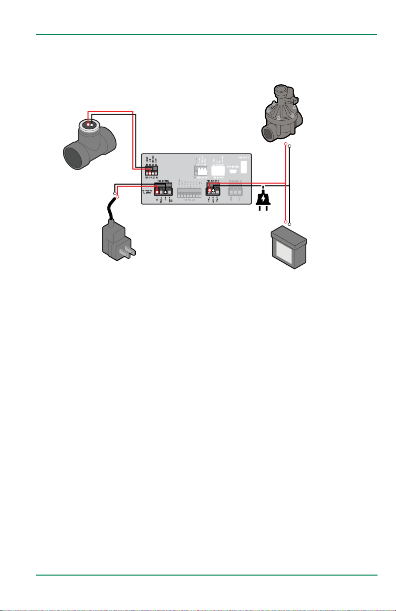
Wiring the PT5002
WIRING THE PT5002
At installation, be sure to comply with the following requirements:
• Disconnect power to the unit before attempting any connection or service to
the unit�
• Avoid using machine power service for AC power� When possible, use a
dedicated circuit or a lighting circuit�
• Observe all local electrical codes�
• The unit must be wired with wires and/or cables with a minimum temperature
rating of 167° F (75° C)�
TO PREVENT ACCIDENTS, DO NOT APPLY POWER UNTIL ALL OTHER
CONNECTIONS HAVE BEEN COMPLETED.
Figure 3: One sensor input, analog output
THE PT5002 IS MICROPROCESSOR CONTROLLED. IT IS VERY IMPORTANT THAT THE
POWER SUPPLY BE FREE OF ELECTRICAL NOISE. AVOID USING POWER LINES THAT
FEED HEAVY LOAD ELECTRICAL DEVICES SUCH AS PUMPS AND MOTORS.
Page 16 June 2020
 Loading...