QUICK START GUIDE FOR SPRINKLER PUMP
MODEL BPUMP1HP, BPUMP1-5HP
SPRINKLER PUMP QUICK REFERENCE GUIDE SEE INSTRUCTION MANUAL FOR
COMPLETE DETAILS
1 TYPICAL INSTALLATION
NOTE: This pump is equipped with a 2 in. inlet for maximum water spray.
•2 in. inlet (suction) opening can be reduced with some loss in performance. If reducing below
1-1/2 in., call factory.
•1-1/2 in. outlet (discharge) pipe can be reduced with some loss in performance. If reducing below 1-1/4 in., call factory.
60 ft. max. Inlet pipe to water
Pipe |
Outlet Pipe |
|
Support |
|
|
Vertical |
|
|
Lift |
|
|
25 ft. |
Inlet |
|
max |
|
|
Pipe |
|
|
|
|
|
Water Level |
Motor Cover |
|
Foot Valve |
Discharge to |
|
with Filter |
Sprinkler System |
|
Screen |
|
|
Questions, problems, missing parts? Before returning to your retailer, call our customer
STOP service department at 1-866-544-1406.
2 |
WHAT CONTROLS WILL YOU USE WITH |
|
THIS PUMP? |
NOTE: This pump can be used with a variety of controls. See control manufacturer’s instructions for details.
|
|
|
|
|
|
|
|
|
|
|
|
|
|
|
|
|
|
|
|
|
|
|
|
|
|
|
|
|
|
|
|
|
|
|
|
|
|
|
|
|
|
|
|
|
|
|
|
|
|
|
|
|
|
|
|
|
|
|
|
|
|
|
|
|
|
|
|
|
|
|
|
|
|
|
|
|
|
|
|
|
|
|
|
|
|
|
|
|
|
|
|
|
|
|
|
|
|
|
|
|
|
|
|
|
|
|
|
|
|
|
|
|
|
|
|
|
|
|
|
|
|
|
|
|
|
|
|
|
|
|
|
|
|
|
|
|
|
|
|
|
|
|
|
|
|
|
|
|
|
|
|
|
|
|
|
|
|
|
|
|
|
|
|
|
|
|
|
|
|
|
|
|
|
|
|
|
|
|
|
|
|
|
|
|
|
|
|
|
|
|
|
|
|
|
|
|
|
|
|
|
|
|
|
|
|
|
|
|
|
|
|
|
|
|
|
|
|
|
|
|
|
|
|
|
|
|
|
|
|
|
|
|
|
|
|
|
|
|
|
|
|
|
|
|
|
|
|
|
|
|
|
|
|
|
|
|
|
|
|
|
|
|
|
|
|
|
|
|
|
|
|
|
|
|
|
|
|
|
|
|
|
|
|
|
|
|
|
|
|
|
|
|
|
|
|
|
|
|
|
|
|
|
|
|
|
|
|
|
|
|
|
|
|
|
|
|
|
|
|
|
|
|
|
|
|
|
|
|
|
|
|
|
|
|
|
|
|
|
|
|
|
|
|
|
|
|
|
|
|
|
|
|
|
|
|
|
|
|
|
|
|
|
|
|
|
|
|
|
|
|
|
|
|
|
|
|
|
|
|
|
|
|
|
|
|
|
|
|
|
|
|
|
|
|
|
|
|
|
|
|
|
|
|
|
|
|
|
|
|
|
|
|
|
|
|
|
|
|
|
|
|
|
|
|
|
|
|
|
|
|
|
|
|
|
|
|
|
|
|
|
|
|
|
|
|
|
|
|
|
|
|
|
|
|
|
|
|
|
|
|
|
|
|
|
|
|
|
|
|
|
|
|
|
|
|
|
|
|
|
|
|
|
|
|
|
|
|
|
|
|
|
|
|
|
|
|
|
|
|
|
|
|
|
|
|
|
|
|
|
|
|
|
|
|
|
|
|
|
|
|
|
|
|
|
|
|
|
|
|
|
|
|
|
|
|
|
|
|
|
|
|
|
|
|
|
|
|
|
|
|
|
|
|
|
|
|
|
|
|
|
|
|
|
|
|
|
|
|
|
|
|
|
|
|
|
|
|
|
|
|
|
|
|
|
|
|
|
|
|
|
|
|
|
|
|
|
|
|
|
|
|
|
|
|
|
|
|
|
|
|
|
|
|
|
|
|
|
|
|
|
|
|
|
|
|
|
|
|
|
|
|
|
|
|
|
|
|
|
|
|
|
|
|
|
|
|
|
|
|
|
|
|
|
|
|
|
|
|
|
|
|
|
|
|
|
|
|
|
|
|
|
|
|
|
|
|
|
|
|
|
|
|
|
|
|
|
|
|
|
|
|
|
|
|
|
|
|
|
|
|
|
|
|
|
|
|
|
|
|
|
|
|
|
|
|
|
|
|
|
|
|
|
|
|
|
|
|
|
|
|
|
|
|
|
|
|
|
|
|
|
|
|
|
|
|
|
|
|
|
|
|
|
|
|
|
|
|
|
|
|
|
|
|
|
|
|
|
|
|
|
|
|
|
|
|
|
|
|
|
|
|
|
|
|
|
|
|
|
|
|
|
|
|
|
|
|
|
|
|
|
|
|
|
|
|
|
|
|
|
Pump Start Relay |
|
|
|
|
|
|
|
|
|
|
Pressure Switch with |
|||||||||||||||||||||||||||||||||
|
|
|
|
|
|
|
|
|
|
|
|
|
|
|
|
|
|
|
|
|
|
|
|
|
|
|
|
Tank |
||||||||||||||||
|
|
|
|
|
|
|
|
|
|
|
|
|
|
|
|
|
|
|
|
|
|
|
|
|
|
|
|
|
|
|
|
|
|
|
|
|
|
|
|
|
|
|
|
|
|
|
|
|
|
|
|
|
|
|
|
|
|
|
|
|
|
|
|
|
|
|
|
|
|
|
|
|
|
|
|
|
|
|
|
|
|
|
|
|
|
|
|
|
|
|
|
|
|
|
|
|
|
|
|
|
|
|
|
|
|
|
|
|
|
|
|
|
|
|
|
|
|
|
|
|
|
|
|
|
|
|
|
|
|
|
|
|
|
|
|
|
|
|
|
|
|
|
|
|
|
|
|
|
|
|
|
|
|
|
|
|
|
|
|
|
|
|
|
|
|
|
|
|
|
|
|
|
|
|
|
|
|
|
|
|
|
|
|
|
|
|
|
|
|
|
|
|
|
|
|
|
|
|
|
|
|
|
|
|
|
|
|
|
|
|
|
|
|
|
|
|
|
|
|
|
|
|
|
|
|
|
|
|
|
|
|
|
|
|
|
|
|
|
|
|
|
|
|
|
|
|
|
|
|
|
|
|
|
|
|
|
|
|
|
|
|
|
|
|
|
|
|
|
|
|
|
|
|
|
|
|
|
|
|
|
|
|
|
|
|
|
|
|
|
|
|
|
|
|
|
|
|
|
|
|
|
|
|
|
|
|
|
|
|
|
|
|
|
|
|
|
|
|
|
|
|
|
|
|
|
|
|
|
|
|
|
|
|
|
|
|
|
|
|
|
|
|
|
|
|
|
|
|
|
|
|
|
|
|
|
|
|
|
|
|
|
|
|
|
|
|
|
|
|
|
|
|
|
|
|
|
|
|
|
|
|
|
|
|
|
|
|
|
|
|
|
|
|
|
|
|
|
|
|
|
|
|
|
|
|
|
|
|
|
|
|
|
|
|
|
|
|
|
|
|
|
|
|
|
|
|
|
|
|
|
|
|
|
|
|
|
|
|
|
|
|
|
|
|
|
|
|
|
|
|
|
|
|
|
|
|
|
|
|
|
|
|
|
|
|
|
|
|
|
|
|
|
|
|
|
|
|
|
|
|
|
|
|
|
|
|
|
|
|
|
|
|
|
|
|
|
|
|
|
|
|
|
|
|
|
|
|
|
|
|
|
|
|
|
|
|
|
|
|
|
|
|
|
|
|
|
|
|
|
|
|
|
|
|
|
|
|
|
|
Indexing Valve
3 CHECK YOUR BREAKER BOX
This pump is wired for 230 V
230 V |
NEED
115 V?SEE SECTION 4
115 V
WARNING: Always disconnect pump from electricity before performing any work on the motor.
4 |
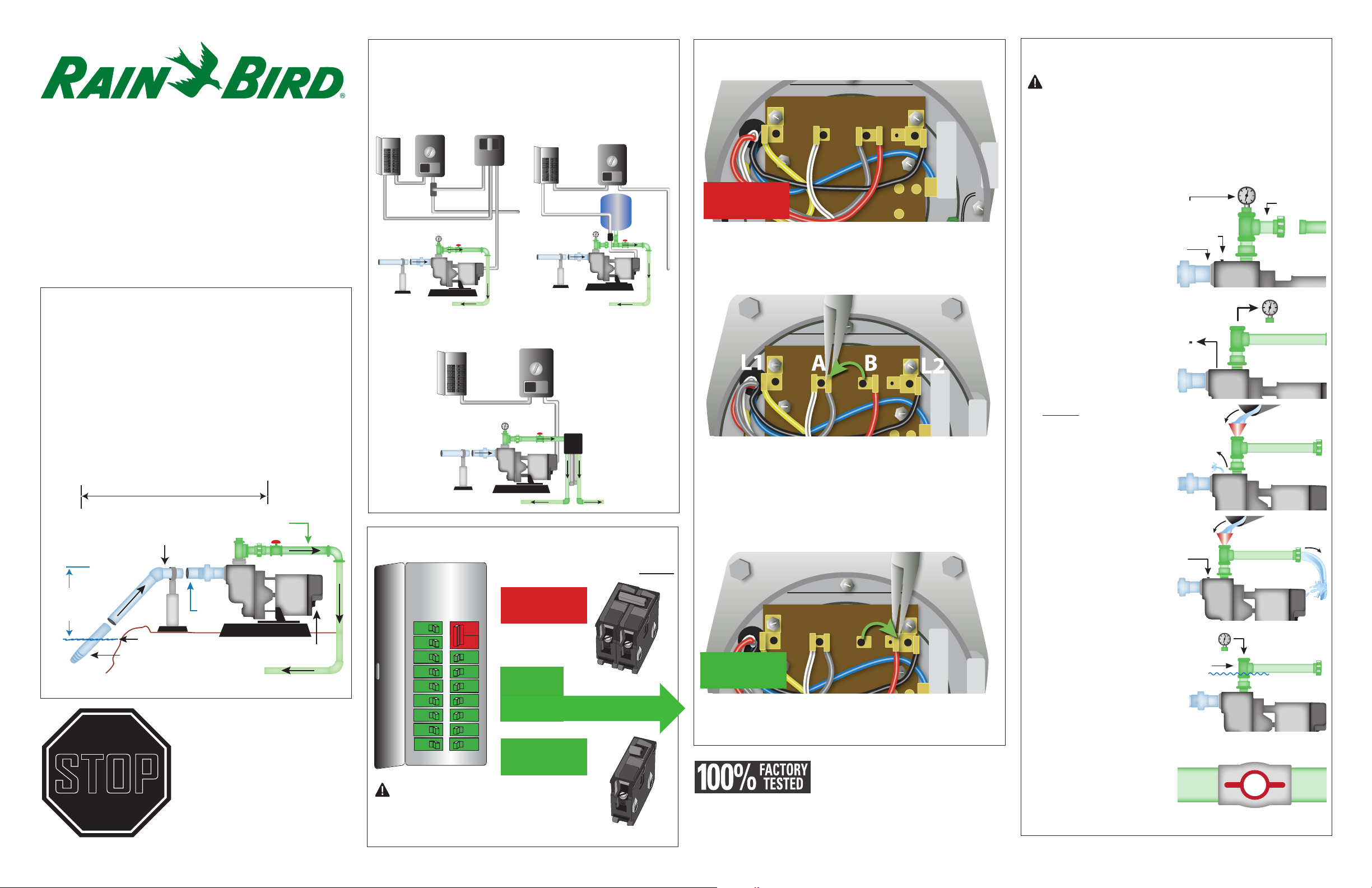
HERE’S HOW TO CHANGE THIS |
||
|
PUMP FROM 230 V TO 115 V |
||
|
L1 |
A B |
L2 |
230 V
The motor of this pump is dual voltage and can run on either 115 V or 230 V. This pump is pre-set in the factory to run at 230 V.
For 115 V service, remove the motor cover and change the following wires on the terminal board:
a.Using a pair of needle-nose pliers, pull the gray wire with the female flag connector from the “B” terminal spade post. Place it to the left on the “A” terminal space post.
L1 A B
L2
115 V
b.Pull the red wire with the female flag connector from the “B” terminal. Place it to the right on the L2 terminal space post.
NOTE: Pump may show water stains as a result of factory water testing.
5 HOW TO PRIME YOUR PUMP
CAUTION: All pumps must be primed (filling the cavity with water) before they are first operated. This may take several gallons of water, as the inlet line will be filled in addition to the pump cavity. The longer the inlet line, the more water is required to prime.
1. Disconnect the
outlet union and |
|
|
|
|
|
|
|
|
|
|
|
Outlet |
|||||||
Priming |
|
|
|
|
|
|
|
|
|
|
|
|
|
||||||
plug with |
|
|
|
|
|||||||||||||||
|
|
|
|
||||||||||||||||
|
|||||||||||||||||||
separate the pipe. |
pressure gauge |
|
|
|
|
|
|
||||||||||||
|
|
|
|
|
|
||||||||||||||
|
|
|
|
|
|
||||||||||||||
|
|
|
|
|
|
||||||||||||||
|
|
|
|
|
Air relief |
|
|
|
|
|
|
||||||||
|
|
|
|
|
|
|
|
|
|
||||||||||
|
|
|
|
|
|
|
|
|
|
||||||||||
|
Inlet |
|
plug |
|
|
|
|
|
|
|
|
|
|||||||
|
|
|
|
|
|
|
|
|
|
|
|
|
|||||||
|
|
|
|
|
|
|
|
|
|
|
|||||||||
|
|
|
|
|
|
|
|
||||||||||||
|
|
|
|
|
|
|
|
|
|
||||||||||
|
|
|
|
|
|
|
|||||||||||||
|
|
|
|
|
|
|
|||||||||||||
|
|
|
|
|
|
|
|
|
|
|
|
|
|
|
|
|
|
|
|
|
|
|
|
|
|
|
|
|
|
|
|
|
|
|
|
|
|
|
|
|
|
|
|
|
|
|
|
|
|
|
|
|
|
|
|
|
|
|
|
|
|
|
|
|
|
|
|
|
|
|
|
|
|
|
|
|
|
|
|
|
|
|
|
|
|
|
|
|
|
|
|
|
|
|
|
|
|
|
|
|
|
|
|
|
|
|
|
|
|
|
|
|
|
|
|
|
|
|
|
|
|
|
|
|
|
|
|
|
|
|
|
|
|
|
|
|
|
|
|
|
|
|
|
|
|
|
|
|
|
|
|
|
|
|
|
|
|
|
|
2. Remove priming plug with pressure gauge and the air relief plug on top of pump.
3. Slowly fill pump cavity until water comes out of the air relief hole.
4. Replace air relief plug and continue adding water to pump cavity until water
comes out the open
outlet pipe at the open
union.
5.Wait 10 minutes to see if water level drops below the pipe tee. If level drops, check foot valve. If level stays constant, re-install the priming plug.
6.Reconnect union on outlet pipe. Open the ball valve (turn handle to line up with pipe), and then
turn on breaker to start pump.
Pipe
Tee
D41967