

Page 1

AUTO-EC-3-E-PLC
Electric Filter Backwash Controller
Operation & Maintenance Manual
Page 2

Contents
Controller Basics 3
Controller Components 4
Screen Flow Diagram 5
Controller Functions 6
Installation 7
Warranty 8
AUTO-EC-3-E-PLC Controller Manual
Contents
www.rainbird.com2
Page 3
AUTO-EC-3-E-PLC Controller Manual
EC-3-LP-PLC
Controller Basics
Controller Basics
Auto-EC-3-E-PLC Backwash Controllers are designed to monitor and activate a cleaning cycle
for three Low Pressure Series lters in parallel.
The controller allows the user to adjust the ush
duration, dwell time between backwashes,
and the specied periodic backwash. Other
features include manual start, counter reset,
and alarmreset.
The controller receives an open/closed signal
via terminals 1 through 6. This signal is from the
dierential pressure gauge, and means that the
gauge has reached a preset value. Reaching the
preset value (usually 7 psid) tells the controller
that debris has collected on the screen element,
and that an automatic backwash will activate.
D502
SCR501D501
A2
L1
M
O
V
5
10
F2
F1
MOV503
SW501
L2
115 230
S2
C504
18090
INHIBIT
SW502
S3
D502
SCR501D501
A2
L1
M
O
V
5
0
1
F2
F1
MOV503
SW501
L2
115 230
S2
C504
18090
INHIBIT
SW502
S3
D502
SCR501D501
A2
L1
M
O
V
5
10
F2
F1
MOV503
SW501
L2
115 230
S2
C504
18090
INHIBIT
SW502
S3
13 14
13 14
13 14
13 14
13 14
9
5
1
11 12 13
13 14
9
9
9
5
5
5
1
1
1
9
9
5
5
1
1
5 7
4
321 14 1516171819 20 21 22 23 24 25
109
6
8
D503
SCR502
02
V5
O
M
03
02
1
5
0
C
R5
R5
C501
02
C
I5
A1
SO502
+
C502
IC501
METER
CL
IL501
S1
TORQUEDECELACCEL
MIN SPDMAX SPD
IR COMP
D503
SCR502
02
V5
O
M
03
02
1
5
0
C
R5
R5
C501
02
C
I5
A1
SO502
+
C502
IC501
METER
CL
IL501
S1
TORQUEDECELACCEL
MIN SPDMAX SPD
IR COMP
D503
SCR502
02
V5
O
M
03
02
1
5
0
C
R5
R5
C501
02
C
I5
A1
SO502
+
C502
IC501
METER
CL
IL501
S1
TORQUEDECELACCEL
MIN SPDMAX SPD
IR COMP
26
When a closed signal is sensed on terminals
1 and 2 for a 5 second period, the backwash
sequence begins. The backwash sequence
is: station 1 energizes for the ush duration,
then an idle period for the dwell duration,
then station 2 energizes for the ush duration,
another dwell, and then station 3 energizes for
the ushduration.
Controls
A. Panel enclosure: NEMA 4X
B. Control panel for each lter module shall
include:
1. All required control and power elements
to provide automatic self- cleaning system
operations.
2. Main power disconnect switch
3. Starters
4. Transformer
5. PLC
6. Relays
7. Timers
8. Alarm logic modules
9. TIME & DP, and DP ONLY modes of operation with two position selector switch.
10. Indicating lights
C. Depending on mode of operation, control
Auto-EC-3-E-PLC
panel will be responsible for opening the electric exhaust ball valve and starting the motor to
rotate the cleaning element. After the cleaning
interval is complete, control panel shall stop the
motor, close the exhaust valve, and reset the
cleaning cycle for the next operation.
D. With the selector switch in the TIME&DP
position, timers shall intermittently initiate the
cleaning cycle at preset adjustable intervals
ranging from 0 to 24 hours for the length of
time necessary to complete one cleaning cycle.
E. A dierential pressure switch shall be
arranged on the lter or across the inlet and
outlet piping of the lter to override the timer
in the TIME&DP mode or acting alone in the
DP ONLY mode to initiate the cleaning cycle
whenever a dierential pressure across the lter
exceeds a preset value. The dierential pressure
switch shall continue to operate the cleaning
cycle until the dierential pressure across the
lter returns to normal or an adjustable timer
inside the control panel elapses. If the cleaning
cycle continues until this preset timer elapses,
then the control panel shall shut down the
cleaning operation completely causing the red
alarm FAULT light to glow on the cover of the
control panel and send a 24 volt AC alarm signal
to terminals 17 and 18 inside the control panel.
F. A “TEST” button shall be located on the control panel door that will initiate a cleaning cycle
upon demand.
G. A “RESET” button shall be located on the
control panel door.
H. Control panel and all components of each
control panel shall be Underwriter’s Laboratory
listed.
I. Additional features
1. Flush in progress - relay contact closure
output
2. System fault alarm - relay contact closure
output
3www.rainbird.com
Page 4

EC-3-LP-PLC
TORQUEDECELACCEL
S3
S2
INHIBIT
C504
MIN SPDMAX SPD
18090
SW502
IL501
CL
10
5
V
O
M
L1
L2
F1
MOV503
SW501
F2
SCR501D501
R5
02
SO502
+
METER
-
D502
A2
M
O
V5
02
D503
A1
IR COMP
IC501
C502
S1
C
5
03
C
I 5
02
C501
R5
0
1
SCR502
115 230
TORQUEDECELACCEL
S3
S2
INHIBIT
C504
MIN SPDMAX SPD
18090
SW502
IL501
CL
1
0
5
V
O
M
L1
L2
F1
MOV503
SW501
F2
SCR501D501
R5
02
SO502
+
METER
-
D502
A2
M
O
V5
02
D503
A1
IR COMP
IC501
C502
S1
C
5
03
C
I 5
02
C501
R5
0
1
SCR502
115 230
TORQUEDECELACCEL
S3
S2
INHIBIT
C504
MIN SPDMAX SPD
18090
SW502
IL501
CL
10
5
V
O
M
L1
L2
F1
MOV503
SW501
F2
SCR501D501
R5
02
SO502
+
METER
-
D502
A2
M
O
V5
02
D503
A1
IR COMP
IC501
C502
S1
C
5
03
C
I 5
02
C501
R5
0
1
SCR502
115 230
1
5
9
13 14
1
5
9
13 14
1
5
9
13 14
1
5
9
13 14
1
5
9
13 14
1
5
9
13 14
EC-3-LP-PLC
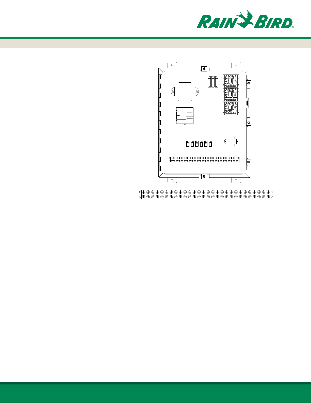
Controller Components
D502
SCR501D501
02
V5
A2
O
M
L1
M
O
V
5
10
F2
F1
MOV503
SW501
L2
115 230
S2
1
4
11
C504
18090
INHIBIT
SW502
S3
MIN SPDMAX SPD
D502
SCR501D501
02
V5
A2
O
M
L1
M
O
V
5
0
1
F2
F1
MOV503
SW501
L2
115 230
S2
C504
18090
INHIBIT
SW502
S3
MIN SPDMAX SPD
D502
SCR501D501
02
V5
A2
O
M
L1
M
O
V
5
10
F2
F1
MOV503
SW501
L2
115 230
S2
C504
18090
INHIBIT
SW502
S3
MIN SPDMAX SPD
17
AUTO-EC-3-E-PLC Controller Manual
Controller Components
D503
SCR502
03
02
1
5
0
C
R5
R5
C501
02
C
I5
A1
SO502
+
C502
IC501
METER
CL
IL501
S1
TORQUEDECELACCEL
IR COMP
D503
SCR502
03
02
1
5
0
C
R5
R5
C501
02
C
I5
A1
SO502
+
C502
IC501
METER
CL
IL501
S1
TORQUEDECELACCEL
IR COMP
D503
SCR502
03
02
1
5
0
C
R5
R5
C501
02
C
I5
A1
SO502
+
C502
IC501
METER
CL
IL501
S1
TORQUEDECELACCEL
IR COMP
7
8
9
3
TEST
HS
FILTER
X
NO.1
TEST
HS
FILTER
X
NO.2
TEST
HS
FILTER
X
NO.3
HS
FAULT
X
RESET
QL
X
QL
X
HS
X
HS
X
CONTROL
POWER
MANUAL
BACKWASH
GEN FAULT
1 FAULT
2
10
5
13
13 14
13 14
13 14
13 14
13 14
16
1
1
9
9
5
5
13 14
9
9
9
9
5
5
5
5
1
1
1
1
6
5 7
4
109
321 14 1516171819 20 21 22 23 24 25
11 12 13
6
8
1. Step-down Transformers. Converts 480
VAC to 110VAC and 110 VAC to 24 VDC.
2. Power. Controls power to the
controllerboard.
3. Fault Reset.
4. Circuit Breaker.
5. Manual Backwash. Manually initiates a
backwash sequence for stations 1-3.
6. Terminal Block: Connections for valves,
motors, and dierential pressure gauge.
7. Test Filter 1. Executes a backwash cycle for
station 1 lter.
12
1
26
8. Test Filter 2. Executes a backwash cycle for
station 2 lter.
9. Test Filter 3. Executes a backwash cycle for
station 3 lter.
10. General Fault. DP fault time exceeded
without relieving dierential pressure.
11. IDEC PLC. Set ush duration, dwell, and
timed backwash
12. DP / DP & Time. Selector switch for DP only
mode or DP & timed interval mode.
13. Fault Filter 1. Indicates fault for station
1lter.
HS
X
DP ONLY
DP & TIME
HS
2 FAULT
X
HS
3 FAULT
X
14. Fault Filter 2. Indicates fault for station
2lter.
15. Fault Filter 3. Indicates fault for station
3lter.
16. 24VDC Relays
17. Motor Drive Boards
14
15
4
321 14 1516171819 20 21 22 23 24 25
Terminals
T1–2. Open/Close terminal for station 1
dierential pressure gauge.
T3–4. Open/Close terminal for station 2
dierential pressure gauge.
T5–6. Open/Close terminal for station 3
dierential pressure gauge.
T7. Motor 1 Red Lead
T8. Motor 1 Black Lead
5 7
6
109
8
T9. Motor 2 Red Lead
T10. Motor 2 Black Lead
T11. Motor 3 Red Lead
T12. Motor 3 Black lead
T13–14. Valves 1-3 Red Lead
T15–16. Valves 1-3 Black Lead
T17. Valve 1 White Lead
T18. Valve 2 White Lead
11 12 13
26
T19. Valve 3 White Lead
T20–21. Input Voltage Hot
T22. Input Voltage Ground
T23–24. Alarm Output
T25–26. Emergency Stop
T27–28. 24VAC for Utility Water Backwash
www.rainbird.com4
Page 5

AUTO-EC-3-E-PLC Controller Manual
Screen Flow Diagram
Screen Flow Diagram
Intro Screen
Home
Manual Operation
Set Times
DP Fault Times
Lifetime Hour Meter
5www.rainbird.com
Page 6

Controller Functions
AUTO-EC-3-E-PLC Controller Manual
Controller Functions
Intro Screen
Advances from Intro to Home screen
DP Limit indicators: Filters 1–3
Controller mode: Auto/Manual
Controller mode: DP only/DP and Time
Activates backwash sequence for lters 1–3
Advance to Set Times screen
Backwashes lters individually
only when manually held
Filter Duration: Sets ush duration (secs)
Advance to DP Fault Times screen
Home
System fault
Manual Operation
System fault
Set Times
Fault indicators: Filters 1–3
Resets controller after fault or emergency stop
Advances to Manual Operation screen
Advances to Set Times screen
Advances to Manual Operation screen
Backwash indication icon: Filters 1–3
Goes back to Home screen
Goes back to Home screen
Advances to Set Times screen
Dwell Time One: Pause between
backwash cycle one and cycle two
Delay after receiving DP, prior to activating backwash
Advances to Manual Operation screen
Dwell Time Two: Pause between
backwash cycle two and cycle three
Timed Interval Delay: Adjustable
setting for timed backwash (secs)
DP Fault Times: Total time reading
DP before triggering fault
Lifetime total backwash per lter
DP Fault Times
Lifetime Hour Meter
Advances to Set Times screen
Advances to Lifetime Hour Meter screen
www.rainbird.com6
Page 7

AUTO-EC-3-E-PLC Controller Manual
5 7
4
321 14 15
Filter 1 Differential Pressure Gauge (Dry)
Output Terminals for Motors (90VDC)
7. Red Lead Motor 1
8. Black Lead Motor 1
9. Red Lead Motor 2
10. Black Lead Motor 2
11. Red Lead Motor 3
12. Black Lead Motor 3
Filter 2 Differential Pressure Gauge (Dry)
3. DP
4. DP
Filter 3 Differential Pressure Gauge (Dry)
5. DP
6. DP
Installation
Installation
Motor 3
Red-11
Black-12
DP Gauge
5 & 6
OUTLET
VALVE 3
Red-13 or 14
Black-15 or 16
White-19
VALVE 2
Red-13 or 14
Black-15 or 16
White-18
Motor 2
Red-9
Black-10
Motor 1
Red-7
Black-8
Isolation
Valve
INLET
DP Gauge
3 & 4
DP Gauge
1 & 2
Differential
Pressure
Gauge
Isolation
Valve
FLUSH
VALVE 1
Red-13 or 14
Black-15 or 16
White-17
Filter
1. DP
2. DP
DP Gauge
1 & 2
Bypass
Valve
7www.rainbird.com
Page 8

AUTO-EC-3-E-PLC Controller Manual
Warranty
Warranty
Rain Bird Filters guarantees all self cleaning water lters, components, and accessories free of defects for one year from the date of installation, or 18 months
from the date of original shipment. Rain Bird will replace any part found defective during the warranty period, provided the equipment in question was
handled, installed, and operated in accordance with the operation and maintenance manual and sound engineering practices. Rain Bird Filters assumes
no liability for incidental or consequential damage resulting from the use of its products, services, or data. Liability is limited to replacement or repair of
products provide by Rain Bird Filters, and no agent or sales representative has authority to extend the warranty period without the express written consent
of Rain Bird Filters, Inc. Shipping charges for returned equipment will be at the expense of the purchaser, and all returned equipment must be sent to Rain
Bird Filters.
www.rainbird.com8
 Loading...