

Rain Bird 500 Series, 700 Series, 900 Series, 551, 700 Operation & Maintenance Manual
...
Rain Bird Golf Rotors
Operations & Maintenance Manual
Aspersores de golf Rain Bird
Manual de operaciones y mantenimiento
Rain Bird® 500, 700 and
900 Series Golf Rotors
Aspersores de golf Rain Bird®
Series 500, 700 y 900
Desert Mountain Golf Club
Scottsdale, Arizona

2
Rain Bird Golf Rotors Operation and Maintenance Manual
Aspersores de golf Rain Bird Manual de operación y mantenimiento
THANK YOU FOR CHOOSING
RAIN BIRD.
We are aware that you have a choice, and we are
happy you chose Rain Bird.
Rain Bird Golf Rotors oer a wide range of features
plus easy maintenance.
This manual shows how to perform common
installation and maintenance procedures. If you
have any comments or questions please call your
local Rain Bird distributor.
TABLE OF CONTENTS
GRACIAS POR ELEGIR RAIN BIRD.
Sabemos que usted puede elegir, y nos complace
que haya optado por Rain Bird.
Los aspersores de golf Rain Bird ofrecen una
amplia variedad de funciones, además de un fácil
mantenimiento.
Este manual muestra cómo realizar los
procedimientos comunes de instalación
ymantenimiento. Si tiene algún comentario
oduda, llame a su distribuidor local de Rain Bird.
ÍNDICE
Important Installation & Maintenance Tips ......3
Required Maintenance Tools ....................4
Cutaway Of Rain Bird 751 Rotor................. 6
Arc Adjustment ...............................7
551/751 Full/Part-Circle Adjustment ............8
Pressure Regulation Adjustment ................9
Manual Operation ............................. 9
Removing the Internal Assembly ..............10
Installing the Internal Assembly ...............11
Replacing the Nozzle .........................12
Replacing the Stator ..........................13
Replacing the Selector Stem...................13
Removing the Valve Assembly.................15
Removing / Installing the Top Serviceable Rock
Screen And Replaceable Valve Seat.............15
Installing the Valve Assembly..................16
Replacing the GBS25 Solenoid Assembly
Or LC Module Assembly .......................17
Rain Bird Professional Customer
Satisfaction Policy ............................18
Appendix 1 – Rotor Troubleshooting Guide .....19
Appendix 2 – Nozzle/Stator Settings ...........24
Consejos importantes de instalación y
mantenimiento ...............................3
Herramientas necesarias para el mantenimiento
...4
Vista interior del aspersor Rain Bird 751..........6
Ajuste del sector............................... 7
551/751 Ajuste de círculo completo/parcial . . . . . . 8
Ajuste de regulación de presión................. 9
Funcionamiento manual .......................9
Extracción del mecanismo interno .............10
Instalación del mecanismo interno.............11
Sustitución de la tobera .......................12
Sustitución del estator ........................13
Sustitución del vástago del selector ............13
Retirada del mecanismo de válvula 15
Retirada / instalación del ltro antigravilla Rock
Screen y el asiento de válvula reemplazable.....15
Instalación del mecanismo de la válvula ........16
Sustitución del mecanismo del solenoide GBS25
oel mecanismo del módulo LC.................17
Política de satisfacción del cliente profesional
deRain Bird..................................18
Apéndice 1 – Guía de solución de problemas
deaspersores ................................19
Apéndice 2 – Ajustes de la tobera/estator ......24
3
Rain Bird Golf Rotors Operation and Maintenance Manual
Aspersores de golf Rain Bird Manual de operación y mantenimiento
IMPORTANT INSTALLATION &
MAINTENANCE TIPS
• To avoid debris problems, ush the system
before installing the ROTOR on the swing joints.
If debris gets in the line, ush the line.
• For ACME thread rotors, you must use an ACME
thread swing joint assembly. DO NOT use
plumbers tape or pipe dope. Do not tighten
completely against swing joint tting. (Turn the
rotor back counter-clockwise one-quarter (¼) of a
turn from tightened position.)
• Rain Bird does not recommend using metal
ttings with Rain Bird Rotors. If metal ttings
must be used, hand tighten only.
• Rain Bird Rotors may be installed at ground level
in all soil types.
• For SAM/hydraulic rotors used in hydraulic
congurations; before you connect the hydraulic
tubing, make sure you bleed the air from the tube
of the hydraulic control module.
• On electric and IC models, be careful to prevent
any debris from entering the Pressure Regulating
System when working on the valve or replacing
the selector stem.
• For part-circle applications, locate the
xed left edge by rotating the nozzle turret
counterclockwise.
CONSEJOS IMPORTANTES DE
INSTALACIÓN Y MANTENIMIENTO
• Para evitar problemas de impurezas, limpie el
sistema antes de instalar el ASPERSOR en los
codos articulados. Si se introduce suciedad en la
línea, límpiela.
• Para aspersores con rosca ACME, deberá usar un
conjunto de codo articulado con rosca ACME.
NO utilice cinta de teón o sellador de tuberías.
No apriete el aspersor tope con el acople del
codo articulado. (Gire el aspersor ¼ de vuelta en
sentido antihorario desde la posición apretada).
• Rain Bird recomienda no usar acoples metálicos con
los aspersores Rain Bird. Si tuviera que utilizar este
tipo de acoples, apriételos a mano únicamente.
• Los aspersores Rain Bird pueden instalarse al nivel
del suelo en todo tipo de terreno.
• Para aspersores SAM/hidráulicos en
conguraciones hidráulicas, asegúrese de purgar
el aire del tubo del módulo de control hidráulico
antes de conectar la tubería hidráulica.
• En los modelos eléctricos e IC, tenga cuidado de
que no entre ninguna impureza en el sistema de
regulación de presión cuando esté trabajando en
la válvula o reemplazando el vástago del selector.
• Para las aplicaciones de círculo parcial, ubique
el tope izquierdo jo moviendo la torreta de la
tobera en sentido antihorario.
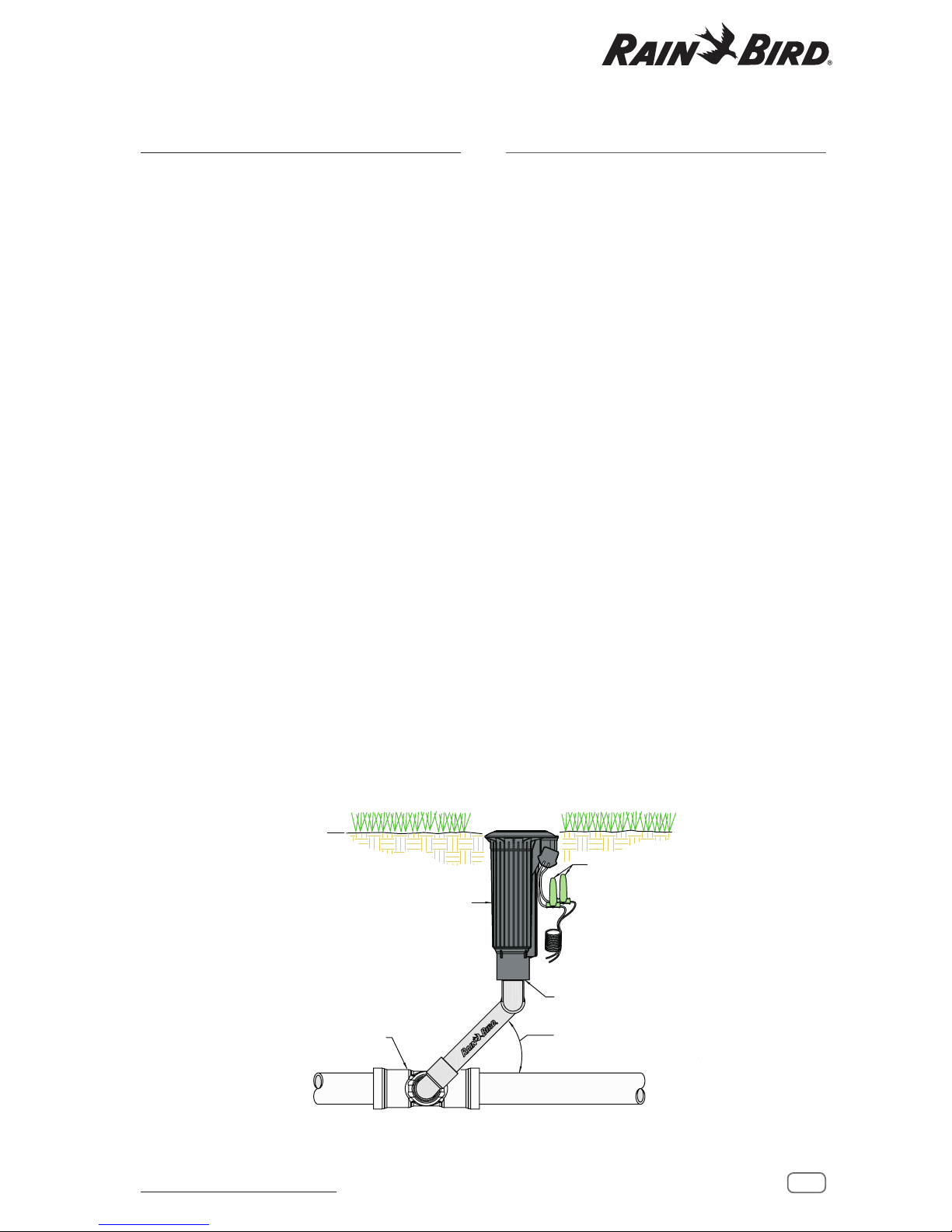
R
FITTING AS REQUIRED
(ACOPLE SEGÚN SEA
NECESARIO)
RAIN BIRD 551/700/751 ROTOR
(ASPERSOR RAIN BIRD 551/700/751)
FINISH GRADE
(SUPERFICIE)
CONTROLLER WIRE
EXPANSION COIL
(BOBINA DE EXPANSIÓN DE CABLE
DEL PROGRAMADOR)
RAIN BIRD CONNECTORS
(CONECTORES RAIN BIRD)
THREADED INLET SIZE: 1 1/4" - ACME
IMPACT ABSORPTION.
(CODO ARTICULADO UNITIZADO RAIN BIRD
AJUSTAR ÁNGULO DEL BRAZO DE COLOCACIÓN DE
CODO ARTICULADO ENTRE 30º Y 45º PARA PERMITIR
UNA ADECUADA ABSORCIÓN DE IMPACTOS).
BETWEEN 30° TO 45° TO ALLOW ADEQUATE
ADJUST ANGLE OF SWING JOINT LAY ARM
RAIN BIRD UNITIZED SWING JOINT
DO NOT USE TEFLON TAPE WITH ACME THREADS.
DO NOT USE PIPE DOPE.
(TAMAÑO DE ENTRADA DE ROSCA: 1 1/4" - ACME
NO UTILICE CINTA DE TEFLÓN CON ROSCAS ACME.
NO UTILICE SELLADOR DE TUBERÍAS).
4
Rain Bird Golf Rotors Operation and Maintenance Manual
Aspersores de golf Rain Bird Manual de operación y mantenimiento
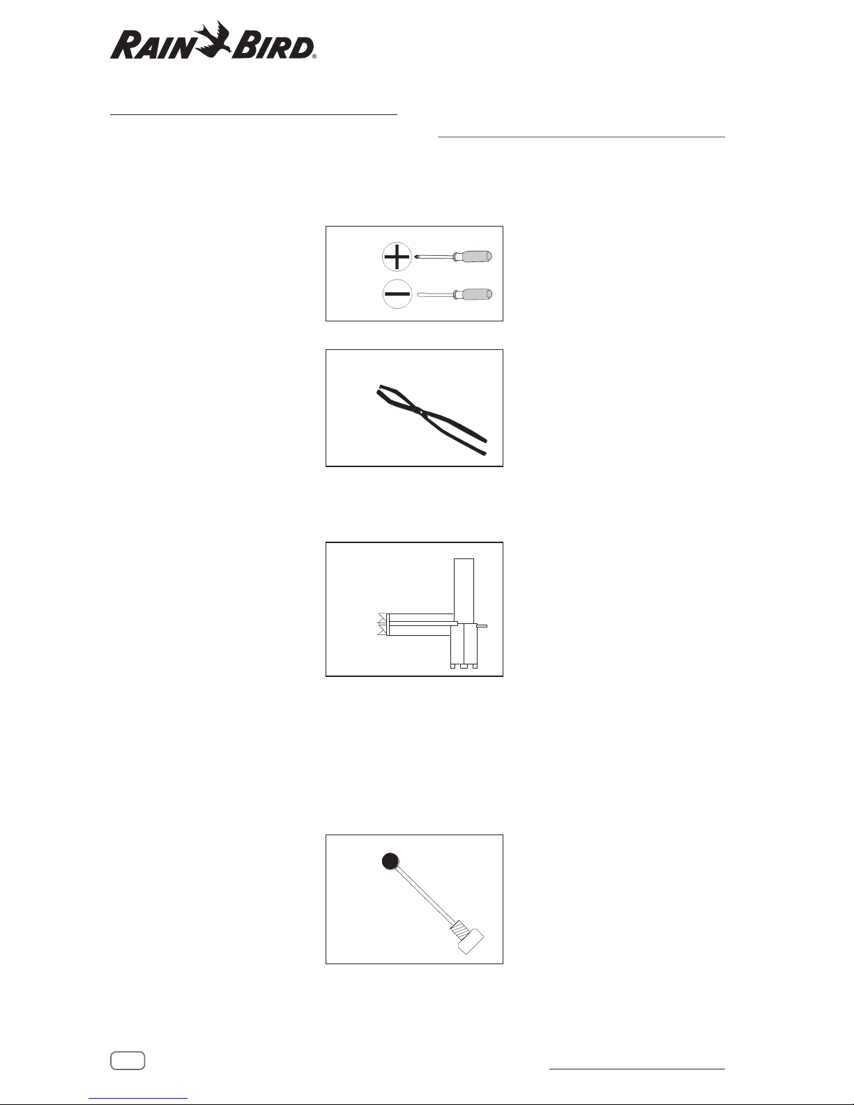
REQUIRED MAINTENANCE TOOLS
To perform maintenance on Rain Bird Series Rotors,
you will need the following tools:
Phillips-head screwdriver
Flat-head screwdriver (#2 size
preferred)
Snap-ring pliers — used to
remove snap rings from inside
the case of the Rotor.
Rain Bird Part Number:
• For 900/950 — Part
#D02203, Model: SRP-900
• For 700//751,551 — Part
#D02236, Model: SR-700
Selector valve key — used to
manually operate and service
electric Rotors.
Rain Bird Part Number:
• For 900/950, 700/751, 551
— Part #B41720, Model:
EGL-SVK
• 7” Selector Valve Key —
Part #D02215, Model:
DR-SVK-7
• 18” Selector Valve Key —
Part #D02221, Model:
DR-SVK-18
Valve insertion tool — used
to insert the valve assembly
to all models.
Rain Bird Part Number:
• For 900/950 — Part
#B41730, Model: VT900NFor
700/751,551 —
Part # B41710 Model: VT-700
HERRAMIENTAS NECESARIAS
PARA EL MANTENIMIENTO
Para efectuar el mantenimiento de la serie de
aspersores Rain Bird, necesitará las siguientes
herramientas:
Destornillador Phillips
Destornillador de punta plana
(preferible nº 2)
Pinzas para anillos de
retención — se usan para
sacar los anillos de retención
de la carcasa del aspersor.
Número de pieza Rain Bird:
• Para 900/950 — Nºdepieza:
D02203, Modelo: SRP-900
• Para 700//751,551 — Nºde
pieza: D0223, Modelo:SR-700
Llave de la válvula del
selector — sirve para el
funcionamiento manual y
el mantenimiento de los
aspersores eléctricos.
Número de pieza Rain Bird:
• Para 900/950, 700/751,
551 — Nº de pieza: B41720,
Modelo: EGL-SVK
• Llave de la válvula del
selector de 7" — Nºdepieza:
D02215, Modelo: DR-SVK-7
• Llave de la válvula del selector
de 18" — Nºdepieza:
D02221, Modelo: DR-SVK-18
Herramienta de inserción
de válvulas — se usa para
insertar el mecanismo de la
válvula en todos los modelos.
Número de pieza Rain Bird:
• Para 900/950 — Nº de pieza:
B41730, Modelo: VT900N Para
700/751,551 — Nº de pieza:
B41710, Modelo: VT-700
5
Rain Bird Golf Rotors Operation and Maintenance Manual
Aspersores de golf Rain Bird Manual de operación y mantenimiento
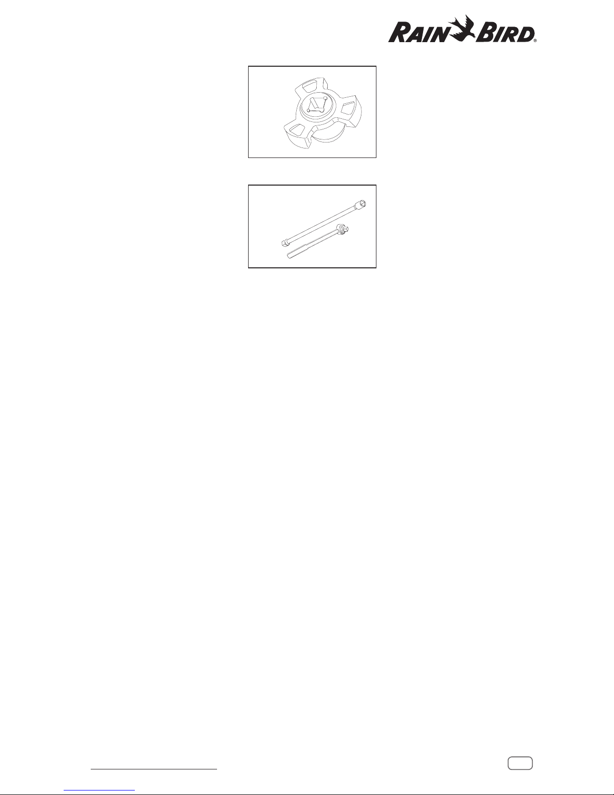
Installation Socket for Top-
Serviceable Rock Screen and
Replaceable Valve Seat on all
valve-in-head rotor models.
Rain Bird Part number:
• Part #D02237, Model:
IS-TSRS
3/8” Socket Wrench &
Extension or 3/8” Speed
wrench & Extension
• A 10” (25,4 cm) minimum
extension is required for
700 & 500 series cases, and
12” (30,5 cm) minimum
extension is required for 900
series cases.
Llave de instalación del ltro
antigravilla Rock Screen
y del asiento de válvula
reemplazable. Seusa en todos
los modelos de aspersor con
válvula integrada.
Número de pieza Rain Bird:
• Nº de pieza: D02237,
Modelo: IS-TSRS
Llave de vaso y extensor de
3/8" o llave dinamométrica y
extensor de 3/8".
• Para las carcasas de las
series 700 y 500 se requiere
un extensor de un mínimo
de 10" (25,4cm) y para las
carcasas de la serie 900,
unode 12" (30,5 cm).
6
Rain Bird Golf Rotors Operation and Maintenance Manual
Aspersores de golf Rain Bird Manual de operación y mantenimiento
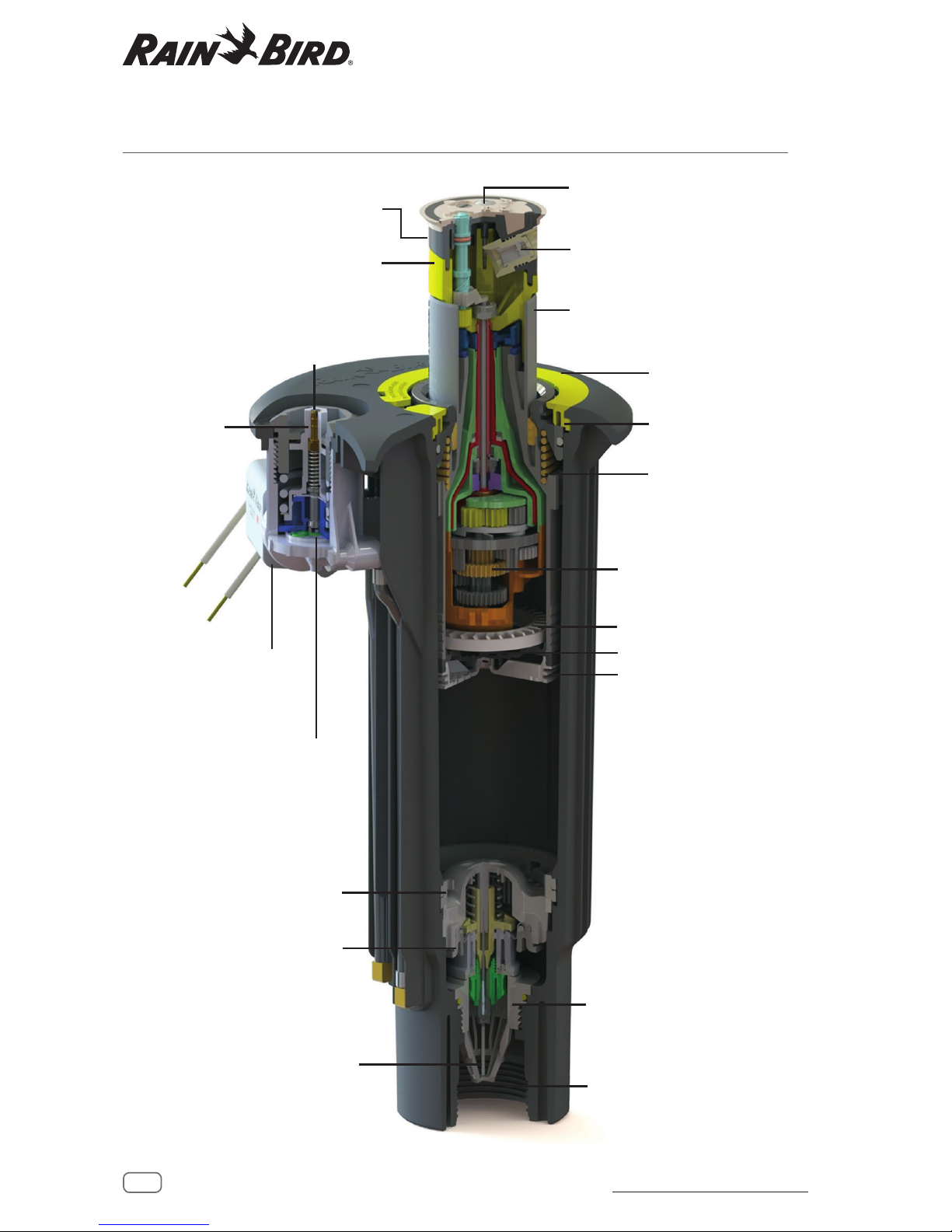
CUTAWAY OF RAIN BIRD 751 ROTOR
VISTA INTERIOR DEL ASPERSOR RAIN BIRD 751
Arc Adjustment Screw
(Tornillo de Ajuste del Arco)
Range Nozzle
(Boquilla Principal)
Internal Assembly
(Ensamblaje Interno)
Bearing Guide
(Taza Guia)
Retract Spring
(Resorte Retractor)
Motor Housing Assembly
(Ensamblaje del Casco del Motor)
Turbine (Turbina)
Stator
Screen (Cedazo)
Lower Dual Snap Rings
(Anillos Retenedores Inferiores)
Valve Assembly
(Ensamblaje de la Valvula)
Thread of Top Serviceable Rock Screen
(Roscas del Cedazo con Servicio
enlaParte Superior)
Case Threads
(Roscas del Casco)
Top Serviceable Rock Screen
(Cedazo con Servicio en la Parte Superior)
Solenoid Assembly
(Ensamblaje del Solenoide)
Selector Valve Assembly
(Ensamblaje de la Valvula Selectora)
Top Adjustable Pressure Regulator
(Regulador de Presión Ajustable
en la Parte Superior)
PRS
Snap Cover
(Anillo de la Tapadera)
Nozzle Housing
(Casco de las Boquillas)
Rear Spreader Nozzle
(Boquilla Esparcidora)
7
Rain Bird Golf Rotors Operation and Maintenance Manual
Aspersores de golf Rain Bird Manual de operación y mantenimiento
ARC ADJUSTMENT
Required Tool: Flat-head screwdriver
On 551/751 series par t/full circle and
950 series part-circle rotors, the LEFT
leg of the sprinkler’s arc is the xed
leg. When shipped from the factory,
the left leg is aligned with the mark
on the side of the case, except 950
series rotors. Align the left leg where
it is needed for your desired watering
pattern while installing the rotor case
on the swing joint.
For 551/751, and 950 Series rotors,
the RIGHT leg of the arc is the
adjustable leg. It is shipped from the
factory at approximately 180 degrees
from the xed leg.
For best results, turn the head ON
to see where both legs “trip” (the
trip point is the point where the
rotor turns and begins rotating in
the opposite direction). To manually
advance the nozzle housing, SLOWLY
move it in the same direction it is
currently moving. After noting where
the head trips, return the head to
the left trip point. CAUTION: Do not
turn the turret manually against
the direction of rotation while in
operation.
Using a at-head screwdriver, turn
the arc adjustment screw on top of
the nozzle housing to reach your
desired arc.
For 551/751 rotors, turn the screw
counterclockwise to add arc, or
clockwise to subtract arc. One
complete turn of the adjustment
screw equals approximately 20
degrees of arc. 551/751 Series rotors
are adjustable from 30° to 345°.
950 Series rotors adjust in the direction opposite from
other Rotors (clockwise to add arc and counterclockwise to
subtract arc), and adjustable from 40° to 345°. Refer to the
arrows on the top of the nozzle housing.
CAUTION: Turning the arc adjustment past the stop may
damage the internal.
Turn on the rotor and let it run through the forward and
backward trip points to verify the arc setting. Repeat steps 1
through 4 as needed. You may also pull the internal assembly
out of the rotor and adjust the arc. Then reinstall the internal
assembly and check for performance.
AJUSTE DEL SECTOR
Herramienta necesaria: Destornillador de cabeza plana
En aspersores de círculo completo/
parcial de la serie 551/751 y
aspersores de círculo parcial de la serie
950, el tope IZQUIERDO del sector del
aspersor es el tope jo. Cuando se
envían de fábrica, el tope izquierdo
está alineado con la marca situada
en el lado izquierdo de la carcasa,
excepto en los aspersores de la serie
950. Alinee el tope izquierdo donde
sea necesario según el patrón de
riego deseado al instalar la carcasa
delaspersor sobre el codo articulado.
Para los aspersores de las series
551/751 y 950, el tope DERECHO del
sector es el tope ajustable. En fábrica se
coloca a unos 180 grados del topejo.
Para obtener mejores resultados,
ENCIENDA el aspersor para localizar
ambos topes (el tope es el punto en
el que el aspersor gira y comienza
a rotar en la dirección opuesta).
Paraadelantar manualmente la torreta
de la tobera, muévala DESPACIO
en la misma dirección en la que se
está moviendo. Después de localizar
dónde cambia de dirección el cabezal,
sitúelo de nuevo en el tope izquierdo.
PRECAUCIÓN: Nogire la torreta
manualmente en dirección
contraria a la rotación durante
elfuncionamiento delaspersor.
Con un destornillador de punta plana,
gire el tornillo de ajuste del sector
localizado en la parte superior de la
torreta de la tobera hasta alcanzar
elsector deseado.
Para aspersores 551/751, gire el
tornillo en sentido antihorario para
aumentar el arco, o en sentido
horario para disminuirlo. Una vuelta
completa del tornillo de ajuste
equivale aproximadamente a un arco
de 20grados. Los aspersores de la
serie 551/751 pueden ajustarse entre
30° y 345°.
Los aspersores de la serie 950 se ajustan en la dirección
opuesta a los otros aspersores (en sentido horario
para aumentar el arco y en sentido antihorario para
disminuirlo) y pueden ajustarse de 40° a 345°. Consulte
las echas de la parte superior de la torreta de la tobera.
PRECAUCIÓN: Si gira el ajuste del sector más allá del tope
podría dañar el mecanismo interno.
Ponga el aspersor en marcha y déjelo correr entre ambos topes
para vericar el ajuste del sector. Repita los pasos 1 a 4 cuanto
sea necesario. También puede sacar el mecanismo interno del
aspersor y ajustar el sector. A continuación, vuelva a instalar
elmecanismo interno y revise su funcionamiento.
8
Rain Bird Golf Rotors Operation and Maintenance Manual
Aspersores de golf Rain Bird Manual de operación y mantenimiento
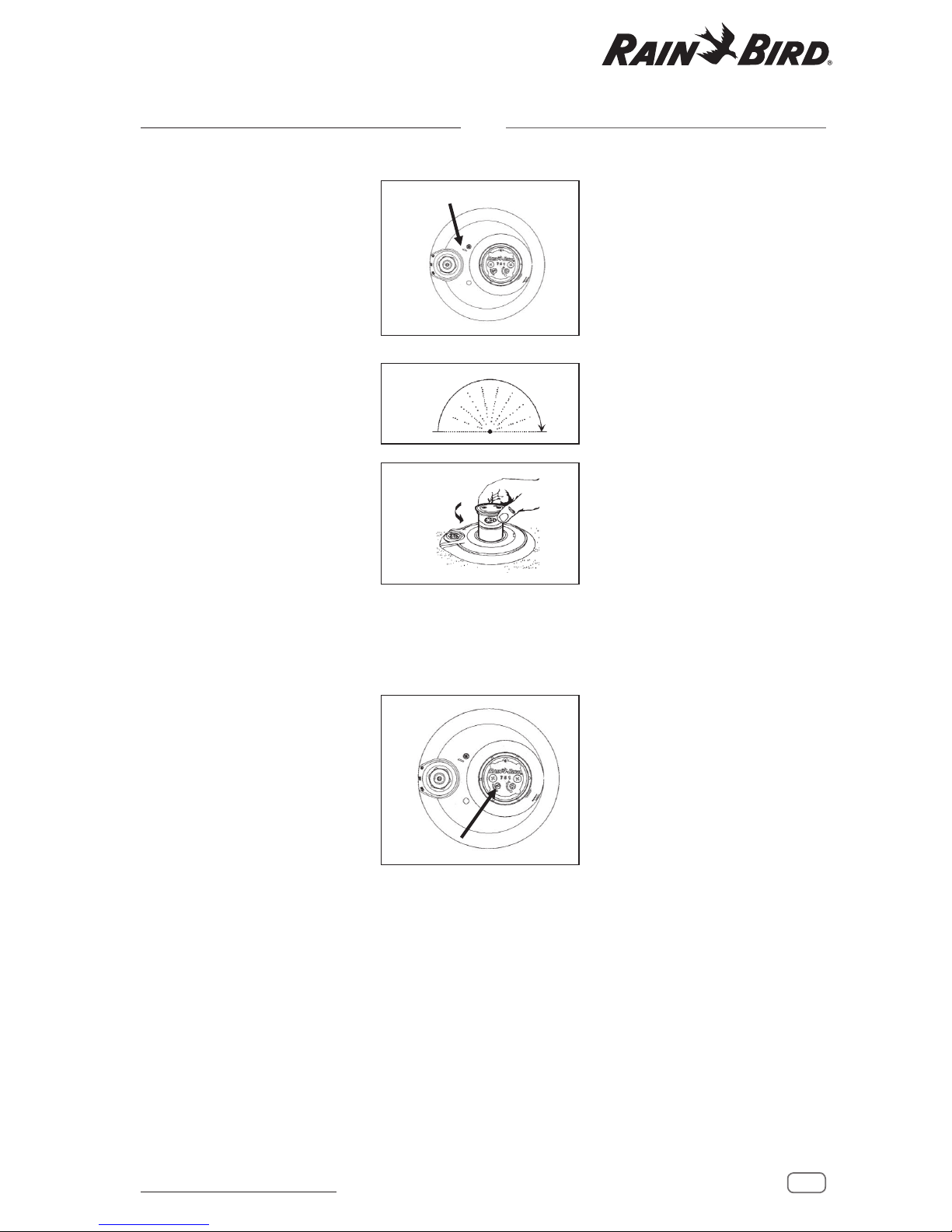
551/751 FULL/PARTCIRCLE
ADJUSTMENT
Required Tool: Flat-head screwdriver
On 551/751 Series full/part-circle
rotors, the LEFT leg of the sprinkler’s
arc is the xed leg. When shipped
from the factory, the left leg is aligned
with the mark on the side of the case.
Align the left leg where it is needed
for your desired watering pattern
while installing the rotor case on the
swing joint.
For 551/751 Series rotors, the RIGHT
leg of the arc is the adjustable leg.
It is shipped from the factory at
approximately 180 degrees from the
xed leg.
The 551/751 Series rotors can
operate in one of two Part Circle arc
settings. The primary arc (Arc A) and a
secondary arc (Arc B)
Note: When internal is removed from
the case, to ensure the rotor is in the
Primary arc, put internal in Full Circle
(see image 6), align arrows on riser
assembly and nozzle base, then put
the unit back into Part Circle mode.
Install the internal in case.
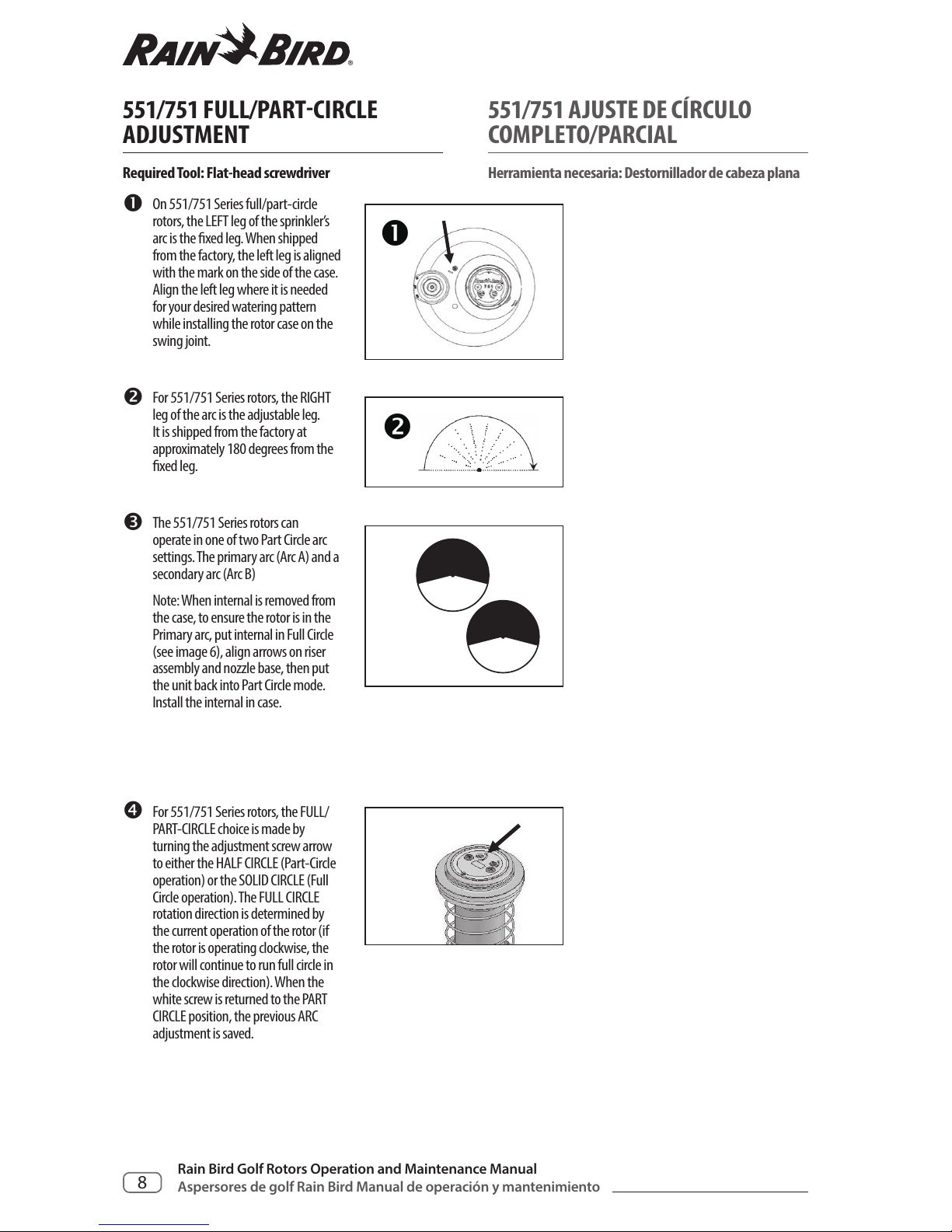
For 551/751 Series rotors, the FULL/
PART-CIRCLE choice is made by
turning the adjustment screw arrow
to either the HALF CIRCLE (Part-Circle
operation) or the SOLID CIRCLE (Full
Circle operation). The FULL CIRCLE
rotation direction is determined by
the current operation of the rotor (if
the rotor is operating clockwise, the
rotor will continue to run full circle in
the clockwise direction). When the
white screw is returned to the PART
CIRCLE position, the previous ARC
adjustment is saved.
551/751 AJUSTE DE CÍRCULO
COMPLETO/PARCIAL
Herramienta necesaria: Destornillador de cabeza plana
En aspersores de círculo completo/
parcial de la serie 551/751, el tope
IZQUIERDO del sector del aspersor es el
tope jo. Cuando se envían de fábrica,
el tope izquierdo está alineado con
la marca situada en el lado izquierdo
de la carcasa. Alinee el tope izquierdo
donde sea necesario según el patrón
de riego deseado al instalar la carcasa
del aspersor sobre el codo articulado.
Para los aspersores de las series
551/751, el tope DERECHO del sector
es el tope ajustable. En fábrica se
coloca a unos 180 grados del tope jo.
Los aspersores de la serie 551/751
pueden funcionar en uno de los dos
ajustes de sector de círculo parcial.
El sector primario (arco A) y un arco
secundario (arco B)
Nota: Si retira el mecanismo interno
de la carcasa, para asegurarse de que
el aspersor está en ajuste de sector
primario, coloque el mecanismo
interno en círculo completo (vea
la imagen 6), alinee las echas del
elevador y de la base de la tobera y
vuelva a poner la unidad en modo de
círculo parcial. Instale el mecanismo
interno en la carcasa.
En los aspersores de la serie 551/751
se puede elegir entre CÍRCULO
COMPLETO/PARCIAL girando el
tornillo de ajuste según indica la
echa, ya sea hacia el MEDIO CÍRCULO
(funcionamiento en círculo parcial)
o hacia el CÍRCULO COMPLETO
(funcionamiento en círculo completo).
La dirección de rotación en CÍRCULO
COMPLETO depende del sentido de
funcionamiento actual del aspersor
(si el aspersor está girando en sentido
horario, continuará girando en este
mismo sentido). Cuando se devuelve
el tornillo blanco a la posición de
CÍRCULO PARCIAL, se guarda el ajuste
de SECTOR anterior.
9
Rain Bird Golf Rotors Operation and Maintenance Manual
Aspersores de golf Rain Bird Manual de operación y mantenimiento
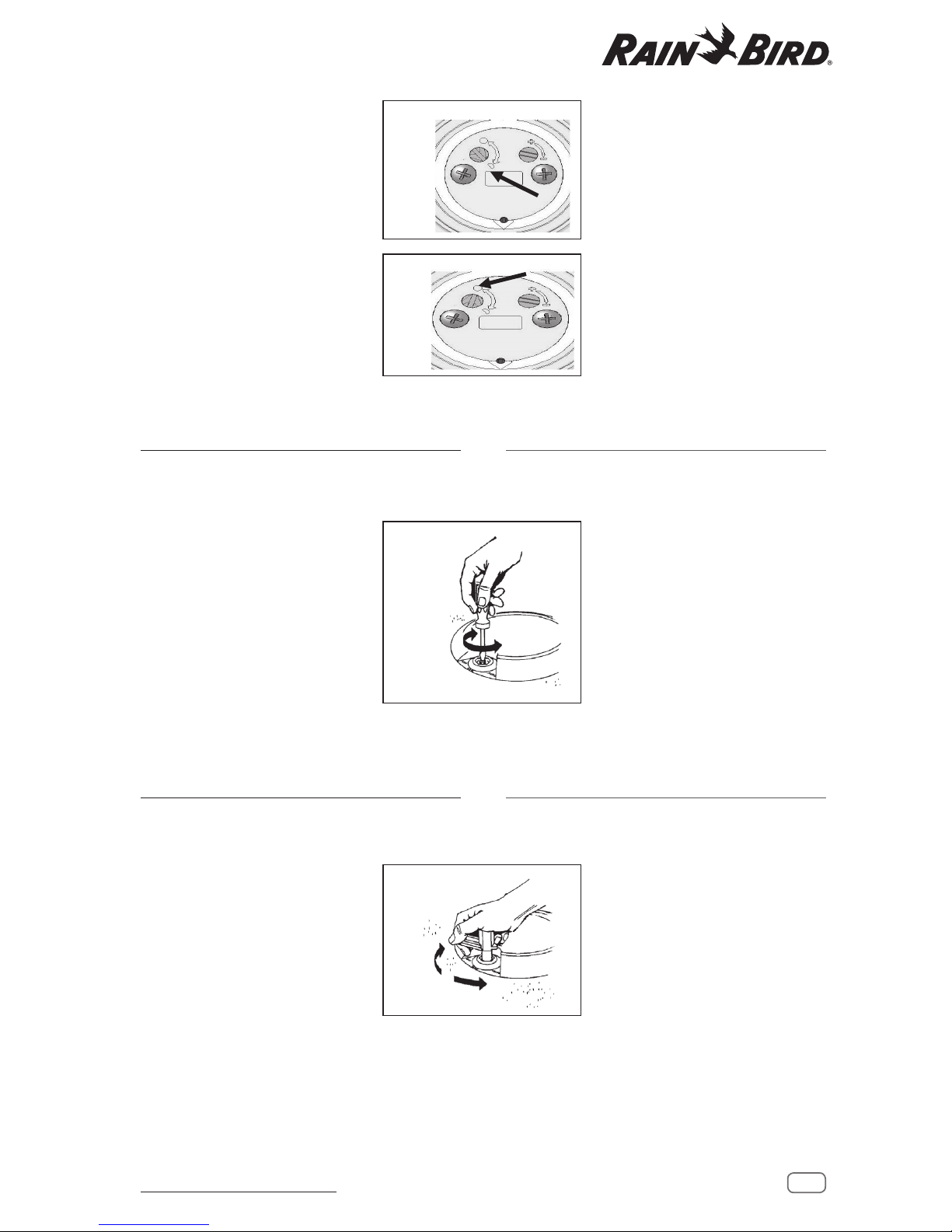
PRESSURE REGULATION
ADJUSTMENT
NOTE: Electric and IC model rotors only
Required Tool: Flat-head screwdriver
To adjust the pressure regulator, use
a at-head screwdriver to turn the
adjustment screw in the center of the
selector on top of the rotor head.
Turn the screw clockwise to increase
pressure, and counterclockwise to
decrease pressure. One full turn is
approximately 10 psi (.7 Bars).
Factory pressure settings are indicated
with blue paint for 70 psi (4,8 Bars)
and white paint for 80 psi (5,5 Bars)
MANUAL OPERATION
NOTE: Electric and IC model rotors only
Required Tool: Selector valve key
To manually operate the rotor, use the
selector valve key to turn the selector
on top of the rotor to the desired
position shown on the rotor case.
The selector has three settings:
CLOCKWISE = MANUAL ON
COUNTERLOCKWISE = AUTO
CENTER = OFF
IMPORTANT NOTE: Locate main nozzle arrow on top of the
rotor. Stand to the left of the arrow to avoid getting sprayed.
During pop-up, a ushing action occurs. Stand at arms reach to
reduce getting wet.
When you are nished manually operating the rotor, return the
selector to the AUTO position.
AJUSTE DE REGULACIÓN
DEPRESIÓN
NOTA: Solo aspersores de modelos eléctricos e IC
Herramienta necesaria: Destornillador de cabeza plana
FUNCIONAMIENTO MANUAL
NOTA: Solo aspersores de modelos eléctricos e IC
Herramienta necesaria: Llave de válvula de selector
The Rotor rotation adjustment screw
in this image is in the PART CIRCLE
operation position.
The Rotor rotation adjustment screw
in this image is in the FULL CIRCLE
operation position.
En esta imagen, el tornillo de ajuste de
giro del aspersor está en posición de
funcionamiento en CÍRCULO PARCIAL.
En esta imagen, el tornillo de
ajuste de giro del aspersor está en
posición de funcionamiento en
CÍRCULOCOMPLETO.
Para ajustar el regulador de presión,
gire con un destornillador de punta
plana el tornillo de ajuste situado en el
centro del selector de la parte superior
de la cabeza del aspersor.
Gire el tornillo en sentido horario para
aumentar la presión y en sentido
contrario para disminuirla. Una vuelta
completa equivale aproximadamente
a 10 psi (0,7 bar).
El ajuste de presión de fábrica se indica
mediante un punto azul para 70 psi
(4,8 bar) y un punto blanco para 80 psi
(5,5 bar).
Para hacer funcionar manualmente el
aspersor, use la llave de la válvula del
selector para girar el selector hasta la
posición deseada de las indicadas en
lacarcasa del aspersor.
El selector tiene tres ajustes:
HORARIO = Encendido manual (ON)
ANTIHORARIO = AUTO
CENTRO = Apagado (OFF)
NOTA IMPORTANTE: Localice la echa de la tobera principal
en la parte superior del aspersor. Sitúese a la izquierda de la
echa para evitar ser rociado. Al elevarse el aspersor sale un
chorro. Aléjese un poco para reducir el riesgo de mojarse.
Cuando termine de usar el aspersor, vuelva a colocar
elselector en la posición AUTO.
 Loading...