

Page 1

Wireless Weather Station
with Software
Owner’s Manual
Please read before using this equipment.
Page 2

Contents
The FCC Wants You to Know ................................. ..................................................... ... ....... 3
FCC Declaration of Conformity ......................................................... ................................ 3
Features .................................................................................................................................. 3
Preparation ............................................................................................................................. 5
A Quick Look at the Weather Station ................................................................................ 5
Understanding the Monitor and Its Display ....................................................................... 7
Installation .............................................................................................................................. 8
Installation Tips ............................................................. ... ... .............................................. 8
Calibrating the Anemometer ............................................... ... .. ......................................... 9
Installing the Anemometer .............................................................................................. 11
Installing the Rain Gauge ................................................................................................ 12
Installing the Outdoor Thermo/Hygro Sensor .................................................................. 13
Installing the Indoor Thermo/Hygro/Baro Sensor ............................................................ 14
Installing the Monitor ....................................................................................................... 15
Using AC Power ............................................................ ... ............................................... 15
Operation .............................................................................................................................. 16
Setting the Time Zone, Time, Date, and Language ........................................................ 16
Viewing the Time/Date/Day of the Week ......................................................................... 17
Using the Daily Alarm ...................................... ... ............................................................. 17
Reading the Weather Forecast Display ..................................................................... ... .. 18
Using the Barometric Pressure Window ......................................................................... 18
Using the Indoor Temperature Window ........................................................................... 20
Using the Outdoor Temperature Window ........................................................................ 21
Viewing and Resetting Max/Min Relative Humidity Records .......................................... 23
Using the Rain Gauge ..................................................................................................... 24
Using the Rain Window ................................................................................................... 24
Using the Wind Window ................................................ ... ... ............................................ 25
Special Features ................................................................................................................... 27
Disconnected Signals ...................................................................................................... 27
Connecting the Monitor to a PC ...................................................................................... 27
Scanning the Monitor’s Channels ................................................................................... 27
Weather References ....................................................................................................... 27
Care ..................................................................................................................................... .. 33
Resetting the Monitor .............................................................................................. ... ... .. 33
Specifications ....................................................................................................................... 33
©
RadioShack and RadioShack.com are trademarks used by RadioShack Corporation.
Accu-Data and AccuWeather are registered trademarks of AccuWeather, Inc.
2
2001 RadioShack Corporation. All Rights Reserved.
AccuWeather for Windows is a trademark of AccuWeather, Inc.
Windows is a trademark of Microsoft Corporation.
Page 3

The FCC Wants You to Know
FCC DECLARATION OF
CONFORMITY
This device complies with Part 15 of the
Rules
. Operation is subject to the following
two conditions: (1) this device may not cause
harmful interference, and (2) this device
must accept any interference received,
including interference that may cause undesired operation.
Product: Wireless Weather
Model: 63-1016
Responsible Party: RadioShack
Phone: 817-415-3200
Station
100 Throckmorton
Fort Worth, TX 76102
FCC
This equipment complies with the limits for a
Class B digital device as specified in Part 15
FCC Rules
of
able protection against radio and TV interference in a residential area.
However, your equipment might cause TV or
radio interference even when it is operating
properly. To eliminate interference, you can
try one or more of the following corrective
measures:
• reorient or relocate the receiving
antenna
• increase the distance between the
equipment and the radio or TV
• use outlets on different electrical circuits
for the equipment and the radio or TV
Consult your local RadioShack store if the
problem still exists.
You must use shielded interface cables with
this equipment.
. These limits provide reason-
Features
An attractive and useful addition to your
home or business, your RadioShack Wireless Weather Station uses 433 MHz radio
signals to send and receive weather data
between its component parts, so you do not
need to run wires between them. Your
weather station lets you monitor the air temperature, relative humidity, and dew point
temperature (indoors and outdoors), as well
as the barometric pressure, wind speed/
direction, wind chill, and rainfall rate (outdoors only). The weather station’s monitor’s
memory lets you recall the maximum and
minimum readings, set an alarm to sound at
The FCC Wants You to Know
a set time or when a set condition is exceeded, and more.
RS-232
The monitor’s
to a PC using a serial cable (not supplied).
The monitor sends data to a connected PC,
so you can use the supplied AccuWeather
for Windows® Weather Station software to
monitor data as it is recorded (real-time), or
recall it later.
The monitor also has an easy-to-read display
that forecasts (12–24 hours in advance) the
weather most likely to occur where the
weather station is located. The weather sta-
jack lets you connect it
®
3
Page 4

tion is ideal for anyone who relies on knowing local weather conditions, such as
gardeners, farmers, or anyone who works
outdoors. It can also help you successfully
plan outdoor activities — from a picnic to
simply knowing when to carry your umbrella!
The supplied software also includes AccuWeather for Windows, which lets you access
AccuWeather’s Accu-Data
®
on-line service
and view or download current and past
weather information — color weather maps
(including radar and satellite images), weather data, forecasts/warnings, and more from
all over the world.
Weather Forecast
— the weather station
provides you with a forecast of the weather
conditions most likely to occur where the
weather station is located.
Weather Symbols
— appear on the monitor,
showing you weather conditions at a glance
with sunny, partly cloudy, cloudy, and rainy
symbols.
Measurement Unit Selection
— lets you
select the measurement unit (such as 12- or
24-hour time format, Fahrenheit or Celsius,
and so on) that the monitor displays in all
modes that use that unit.
The weather station’s other features include:
Display Touch Monitor
— clearly shows
current conditions and various options. The
monitor alerts you when programmed conditions are met.
Weather Measurements
— the weather station measures the air temperature, relative
humidity, and dew point temperature
(indoors and outdoors), as well as the barometric pressure, wind speed/direction, wind
chill, and rainfall rate (outdoors only).
Built-In Memory
— the weather station
records the highest and lowest readings for
temperature, relative humidity, dew point
temperature, maximum wind speed, daily
and accumulated rainfall, and minimum wind
chill. You can reset the memory separately
for each weather type.
Weather Alarms
— let you set the monitor
to sound an alarm for each weather parameter (temperature, wind speed, rainfall rate,
dew-point temperature, and so on) and alert
you when a set weather condition is reached.
Optional PC Connection
— lets you connect the monitor to a personal computer
(using an optional serial cable), so you can
record and store weather data on your PC
using the supplied AccuWeather for Windows software.
Clock Display with Alarm
— shows the
time and date, and lets you set an alarm to
sound at the same time every day.
Mounting Hardware
— lets you easily
mount the weather station’s components in
the locations that best suit your needs.
Liquid Crystal Display
— clearly displays
the monitor’s digital readings and functional
indicators.
Backlight
— makes the monitor’s display
easy to read in low light situations when
using AC power.
Low Battery Indicator
— lets you know
when to change the batteries in the weather
station’s components.
Weather References
— the Owner’s Manual includes a glossary of frequently used
weather terms and a cloud classification
chart.
AccuWeather for Windows
Software Features
Real-Time Display of Weather Conditions
— lets you view the weather station’s data
output as it is received by your PC.
Helps Organize and Store Weather Data
— a variety of features let you organize and
4
Features
Page 5
store some or all of the weather data recorded by your weather station.
Easy Data Access
stored data at any time, print it out in tables
or graphs, and even compare it to normal
and historical conditions for your area.
Accu-Data
lets you view and download current and past
weather information — color weather maps
(including radar and satellite images), weather data, forecasts, warnings, and more — for
your location or from around the world.
Software Registration Benefits
AccuWeather) include some free on-line
time, an on-line subscription discount, free
software upgrades, and other free merchandise.
— AccuWeather’s on-line service
Preparation
— lets you recall the
— (from
Notes:
• The weather station and the information
available in the Accu-Data database are
for educational and hobby use only. Neither RadioShack nor AccuWeather shall
have any responsibility or liability whatsoever for any inconsistency, inaccuracy, or omissions for weather recorded,
reported, or forecasted by the software,
the weather station or the Accu-Data
database or for reliance on such
records, reports, data, or forecasts.
• The modular connection cords supplied
with your weather station are carefully
calibrated and specially designed for it.
Please do not lengthen or shorten these
cables. To avoid inaccurate readings
from the weather instruments, we recommend you do not use extension
cords.
A QUICK LOOK AT THE
WEATHER STATION
Your weather station includes these components and mounting supplies. Be sure to
locate all of these items before you dispose
of the packing material and box.
Note:
Because the indoor thermo/hygro/baro
sensor and outdoor thermo/hygro sensor are
calibrated to different specifications, they
might measure slightly different temperatures even if they are located in the same
area (if for example they are located side by
side before you install them). This is not a
malfunction.
Preparation
Components
Monitor
5
Page 6
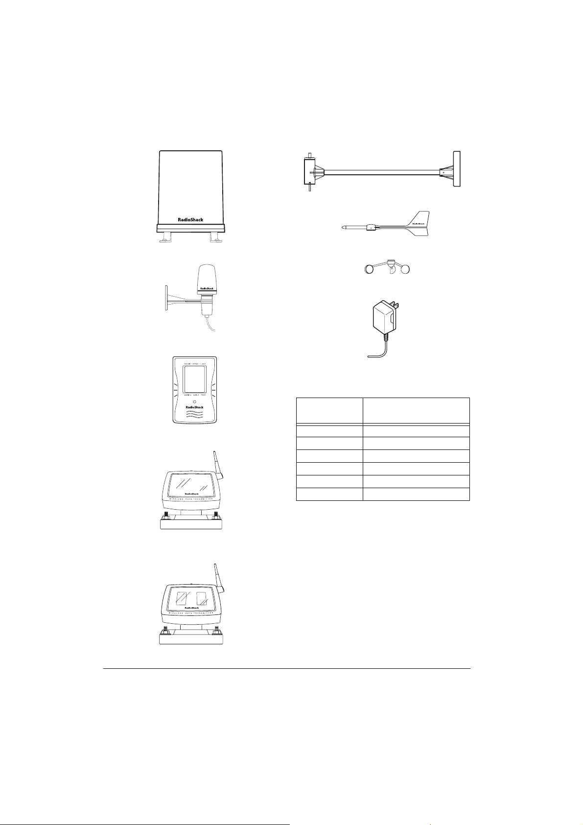
Rain Gauge
Anemometer Base, Arm, and Vane Set
Wind Vane
Outdoor Thermo/Hygro Sensor
Indoor Thermo/Hygro/Baro Sensor
Solar Transmitter for Anemometer
Solar Transmitter for Rain Gauge/
Outdoor Thermo/Hygro Sensor (2)
Wind Cup
AC Adapter
Mounting Hardware
Number
Provided
4M3
2M3
8
16
16
2 Rubber screw covers
Description
×
17 Self-Tapping Screws
×
12 Self-Tapping Screws
1
/4 inch U-Bolts
1
/4 inch Plain Washers
1
/4 inch Hex Nuts
Tools/Additional Supplies Needed
for Installation
In addition to the supplied mounting hardware, you need the following tools and supplies to install your weather station:
• small flat screwdriver
• small Phillips screwdriver
• electric drill
• pencil
• compass
6
Preparation
Page 7
•level
• two screws (if you plan to mount the
monitor on a wall)
1
•mast, 1–1
/4 inches (2.54–3.18 cm) in
diameter (to mount the anemometer)
• batteries (not supplied):
monitor
: 4 AA
Indoor thermo/hygro/baro sensor
: 4 AAA
Notes:
• For the best performance and longest
life, we recommend RadioShack alkaline batteries.
• We recommend that you use lithium batteries in any component that could be
exposed to temperatures between –4°
and –58°F (–20° and –50°C) or colder.
backup power for
solar transmitters
(3): 2 AA (each)
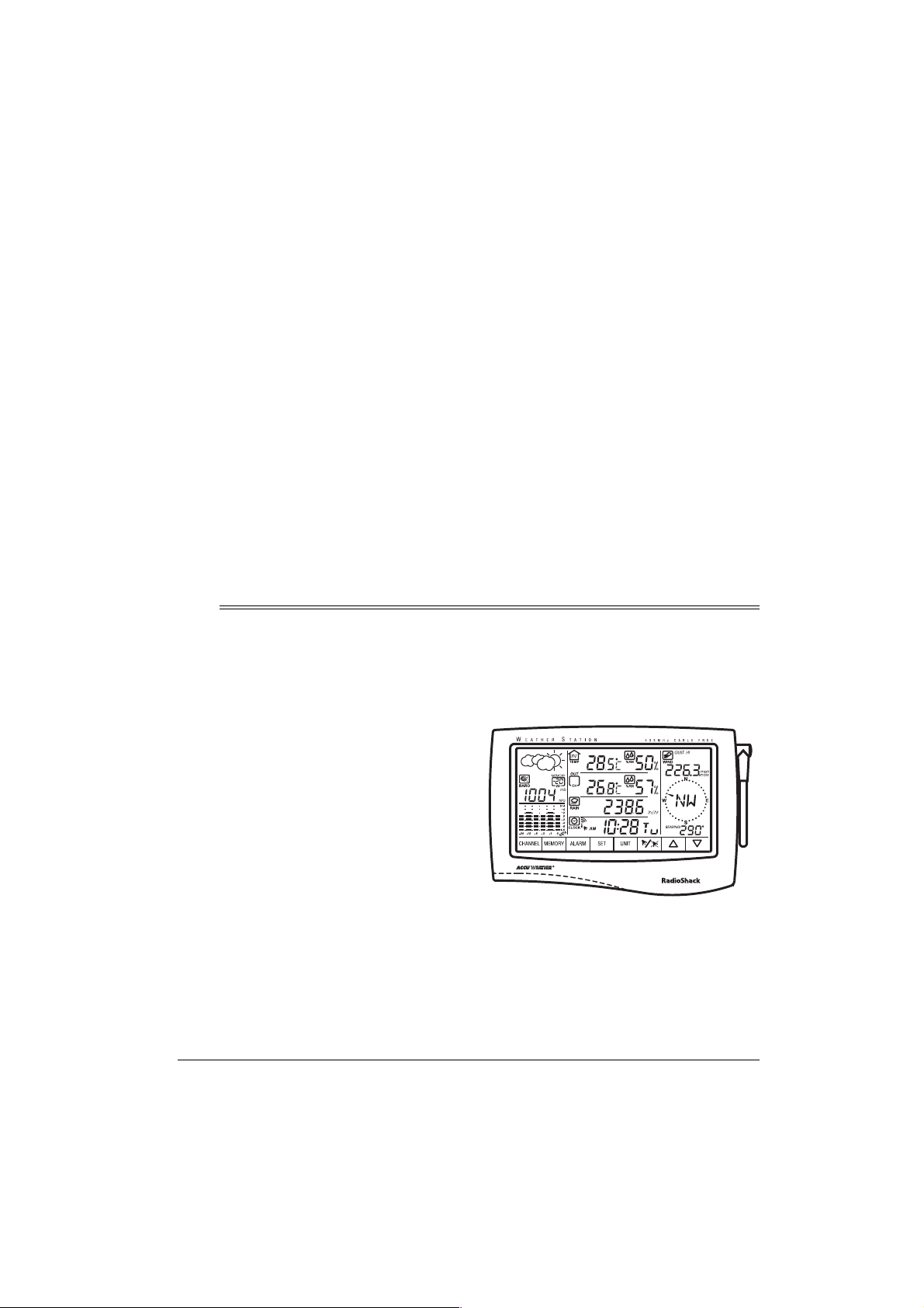
UNDERSTANDING THE MONITOR AND ITS DISPLAY
The weather station’s monitor is divided into various windows: barometric pressure and current
outdoor general condition, barometric bar chart, indoor temperature, outdoor temperature, rainfall, clock, and wind speed and wind direction. Each window disp lays related information for
that item.
The monitor lights for about 12 seconds and a tone sounds each time you press the screen.
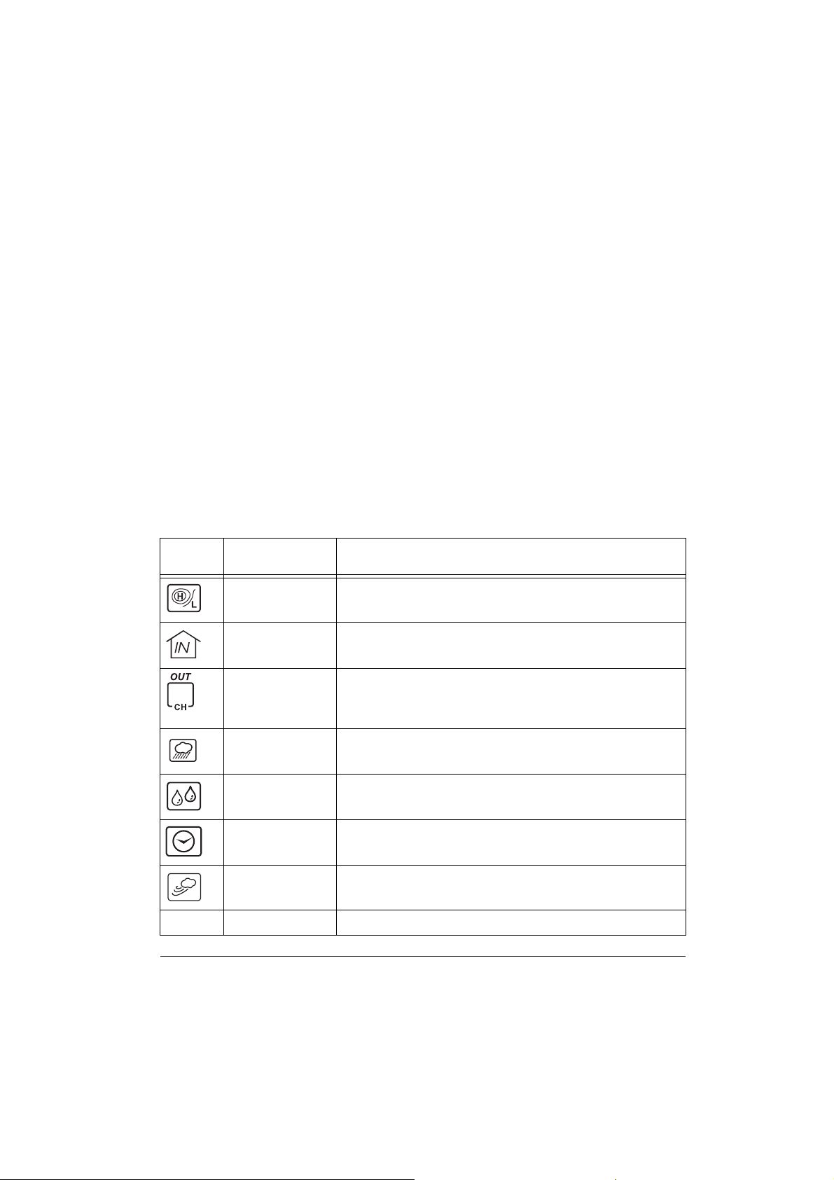
The following chart describes each icon or control.
Icon/
Control
CHANNEL
Description Function
barometric pressure
(absolute/
sea level)
indoor temperature Repeatedly press to toggle among the indoor temperature and the
outdoor
temperature/channel
rain Press to view the rainfall measurement. (See “Using the Rain Win-
relative
humidity
clock Repeatedly press to toggle between the time and date. (See “View-
wind Repeatedly press to toggle between the average wind speed and the
control Repeatedly press to toggle among the outside channels.
Repeatedly press to toggle between the absolute and sea level barometric pressure readings. (See “Using the Barometric Pressure Window” on Page 18.)
indoor dew point temperature. (See “Using the Indoor Temperature
Window” on Page 20.)
Repeatedly press to toggle between the outdoor temperature, dew
point temperature, and windchill. The channel number appears inside
the icon. (See “Using the Outdoor Temperature Window” on
Page 21.)
dow” on Page 24.)
Press to view the relative humidity . (See “Viewing and Resetting Max/
Min Relative Humidity Records” on Page 23.)
ing the Time/Date/Day of the Week” on Page 17.)
gust wind speed. (See “Using the Wind Window” on Page 25.)
Preparation
7
Page 8

Icon/
Control
MEMORY
ALARM
SET
Description Function
control Press the desired mode (such as outdoor temperature), then press
control Press the desired mode (such as outdoor temperature), then press
control Press to store a setting in memory.
MEMORY
ALARM
to view the saved high/low value.
to see the desired alarm condition(s).
UNIT
control Press to toggle among various units of measurement.
alarm on/off Repeatedly press to turn the desired alarm condition on or off.
up Press to increase a value.
down Press to decrease a value.
Installation
INSTALLATION TIPS
Although the solar transmitters for the anemometer, outdoor thermo/hygro sensor, and
rain gauge contain a built-in Ni-MH battery,
they also require a backup battery. See the
assembly sections in this manual for instructions on installing a backup battery in those
components. Replace the backup battery for
these components once a year or
when appears under the corresponding
sensor’s window.
The weather station operates at 433 MHz
and does not require wire installation among
the component parts. To ensure successful
installation and the best performance, we
recommend you follow the preparation,
installation, and connection instructions in
the order they appear in this manual.
1. Select the best location for each
weather station component and carefully
measure the approximate mounting distances.
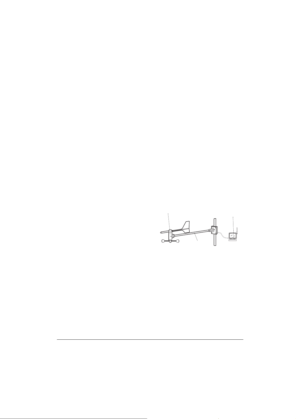
Typical Installation
Anemometer
Weather
Station
Monitor
Thermo/Hygro
Sensor
2. Make sure you have all the tools/supplies necessary to install each component.
3. Assemble and calibrate the anemometer. See “Calibrating the Anemometer”
on Page 9.
Anemometer
Solar Transmitter
Rain Gauge
Solar Transmitter
Rain Gauge
Thermo/
Sensor Solar
Transmitter
Hygro
8
Installation
Page 9
4. Install all components, then connect all
related components.
5. Connect the anemometer, outdoor
thermo/hygro sensor and rain gauge to
their individual solar transmitters to
receive the weather element data. Each
solar transmitter needs two AA batteries
(not supplied) for backup power.
from the monitor. Obstacles between the
solar transmitters and the monitor might
reduce the effective range.
The maximum length of serial cable (not supplied) required to connect the monitor’s
232
jack to a PC is 10 feet, so the monitor
must be located indoors within 10 feet of
your PC.
RS-
Notes:
• Install the anemometer, outdoor thermo/
hygro sensor, and rain gauge outdoors
in a location that provides the best measurement for the weather elements the
instruments are designed for.
• To reduce interference, do not install
individual solar transmitters closer than
3.28 feet (1 meter) to each other.
• We recommend that you use lithium batteries in any component that could be
exposed to temperatures between –4°F
(–20° C) and –58°F (–50° C) or colder.
• If you are installing more than one
weather station in the same area, wait at
least 30 minutes between the installations.
Estimating the Mounting
Distances
To help you find the right location for each
weather station component, follow the tips
listed in “Selecting a Location” on Page 11
that precede the mounting instructions for
that component.
Before you mount any of the components,
we recommend you select a general mounting location for each component first, then
measure the distance between the locations
for components that you will be connecting to
each other to be sure the selected locations
are close enough together.
For the best reception, mount the solar transmitters no more than about 328 ft (100 m)
CALIBRATING THE
ANEMOMETER
Before you mount the anemometer at the
selected mounting location, follow these
steps to calibrate it with the monitor, so the
monitor properly measures wind speed and
direction.
Important:
monitor while you assemble and calibrate the
anemometer. You must temporarily install
the monitor and connect AC power to it. Be
sure to follow these steps before you install
the anemometer at its mounting location.
Assembling the Anemometer
1. Place the wind cup over the thin shaft on
2. Use a Phillips screwdriver to loosen the
You must be able to view the
Anemometer
the anemometer’s bar, use a small Phillips screwdriver to tighten the screw on
the base of the wind cup, then insert one
of the supplied rubber screw covers into
the screw’s hole to protect the screw
from corrosion.
screws on the cover of the anemometer’s solar transmitter, then remove the
cover. The anemometer’s cable and
Anemometer
Solar Transmitter
Bar
Installation
9
Page 10
anemometer solar transmitter are both
labeled with a red tag.
3. Install two AA batteries in the compartment according to the polarity symbols
(+ and –) marked inside.
Cautions:
• Use only fresh batteries of the re-
quired size and recommended type.
• Do not mix old and new batteries, dif-
ferent types of batteries (standard, alkaline, or rechargeable), or rechargeable batteries of different capacities.
4. Insert the anemometer’s modular plug
into the modular jack inside the anemometer’s solar transmitter’s battery
compartment.
• If you are unable to view the monitor
while calibrating the wind vane, you
can use the alignment marks on the
T-bar and wind vane. When the red
mark on the wind vane’s shaft is
aligned with the mark on the outer
edge of the shaft’s base,
%($5,1*
appear next to
tor.
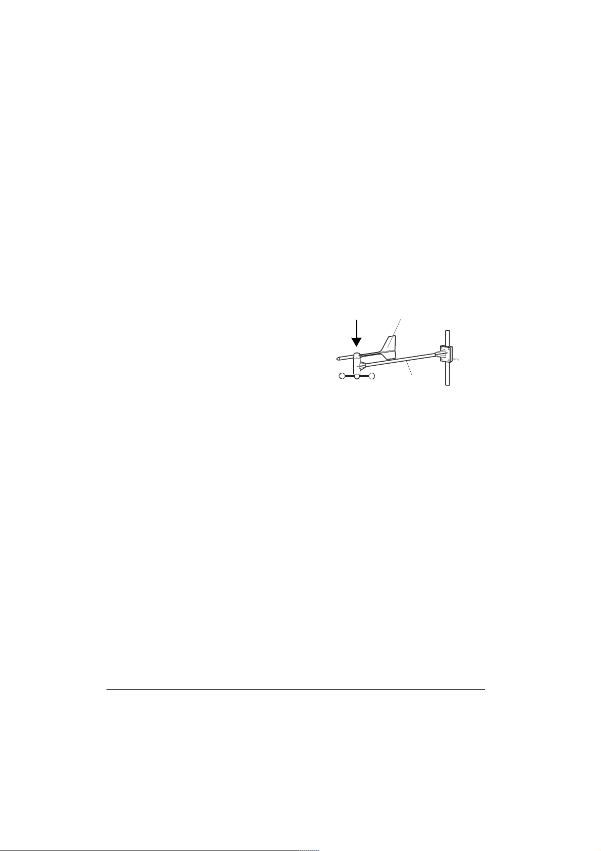
9. Align the wind vane’s tail with the bar as
shown here, then carefully press the
wind vane down onto the shaft. Do not
allow the shaft to turn as you press the
wind vane down onto it.
%($5,1*
%($5,1*%($5,1*
Wind Vane
should
on the moni-
5. Align the rubber gasket on the anemometer’s cord with the groove in the solar
transmitter.
6. Replace the cover and secure it with its
screws. The indicator on the solar transmitter flashes while it is transmitting
data.
7. Insert the supplied AC adapter’s barrel
plug into the monitor’s
plug the other end of the AC adapter into
a standard AC outlet.
All display elements appear. Then the
default time appears.
8. To calibrate the position of the wind
vane’s shaft with the monitor, turn the
shaft until
on the monitor. This shows the wind
direction.
Notes:
• The current position of the shaft
appears on the monitor about 14 seconds after you turn the shaft.
appears next to
DC 12V
jack, then
%($5,1*
%($5,1*
%($5,1*%($5,1*
Bar
10. Use a small Phillips screwdriver to
tighten the screw on the base of the
wind vane. Then insert one of the supplied rubber screw covers into the
screw’s hole to protect the screw from
corrosion.
Important:
monitor’s reading changes (or alignment
marks are no longer aligned), repeat
Steps 8 and 9 before you tighten the
wind vane’s screw. Otherwise, the
weather station will not provide accurate
wind direction data.
11. When you finish calibrating the anemometer, disconnect the AC adapter
from the monitor.
If the shaft turns and the
10
Installation
Page 11

INSTALLING THE
ANEMOMETER
Selecting a Location
Select a mounting location for the anemometer that is:
• outdoors, within 10 feet of its solar transmitter
• not blocked on the top or sides, so wind
can freely reach the anemometer
The best location for the anemometer is usually above roof level on the building where
the monitor is located.
Caution:
er station by lightning, we recommend you
ground the anemometer to the mast, and
ground the mast as directed in the installation instructions provided with the mast.
Note:
a mast (not supplied) about 1–1
(2.54–3.18 cm) in diameter, and the hardware necessary to fasten it to the mounting
location. If you previously installed such a
mast (for mounting an antenna, for example),
you can mount the anemometer and its solar
transmitter on that mast.
Mounting the Anemometer/
Solar Transmitter
Important:
ed in “Assembling the Anemometer” on
Page 9 before you mount the anemometer.
1. If necessary, mount and ground a mast
To prevent damage to your weath-
To mount the anemometer, you need
Be sure you follow the steps list-
as directed in the installation instructions
provided with the mast.
1
/4 inches
ter and wind cup point due south. Then
hold the mounting bracket on the end of
the bar against the place where you plan
to attach it to the mast. Make sure the
wind vane is above the wind cup.
3. Place the supplied U-bolts around the
mast and through the holes on the anemometer’s mounting bracket.
4. Place a washer over both ends of each
U-bolt, then place the ring terminal of
the anemometer’s grounding wire over
the end of one of the bolts.
5. Tighten a nut onto both ends of each
bolt (be sure the nuts are snug but not
too tight).
6. Check the bar’s position on the mast
against the compass to be sure it is still
facing due south. Adjust it if necessary,
then tighten the nuts on the U-bolts.
7. Place the supplied U-bolts around the
mast and through the holes on the anemometer’s solar transmitter’s mounting
bracket.
8. Place a washer over both ends of each
U-bolt.
9. Tighten a nut onto both ends of each
bolt (be sure the nuts are snug but not
too tight), then tighten the nuts on the Ubolts.
10. Loosen the knurled ring on the anemometer’s solar transmitter, adjust the solar
transmitter so it faces the sun, then
tighten the ring to secure the solar transmitter.
Warning:
instructions provided with the mast.
2. Using a compass for reference, point the
bar on which the anemometer is
mounted so the end with the anemome-
Be sure to follow all safety
Installation
11
Page 12

INSTALLING THE RAIN
GAUGE
3. Replace the cylinder on the base, align
its screw holes, then reinsert and tighten
the screws.
Selecting a Location
Select a mounting location for the rain gauge
that is:
• a flat, level surface
• outdoors, within 10 feet of where you
mount the rain gauge’s solar transmitter
• in an area not blocked on the top or
sides, so rain can freely reach the rain
gauge (for example, not under an overhang or too close to a building or fence)
Cautions:
• To prevent false rainfall readings caused
by water splashes, do not choose a
location that is not level or that is too
close to the ground, a swimming pool,
lawn sprinklers, or anywhere water
might accumulate or run off.
• The screen in the cylinder of the rain
gauge filters most debris (such as
leaves) that might fall into the rain
gauge. To avoid frequent build-up of
debris in the cylinder, do not mount the
rain gauge too close to trees or plants.
Removing the Packing Tape
Protective packing tape is installed inside
your rain gauge to protect it from damage
during shipment. Follow these steps to
remove the packing tape before you mount
the rain gauge.
1. Use a small Phillips screwdriver to
remove the screws on the base of the
rain gauge.
2. Lift the rain gauge’s cylinder off its base,
then carefully remove the packing tape
from the bucket assembly.
Connecting the Rain Gauge to a
Solar Transmitter
1. Use a Phillips screwdriver to loosen the
screws on the cover of the rain gauge’s
solar transmitter, then remove the cover.
2. Install two AA batteries in the compartment according to the polarity symbols
(+ and –) marked inside.
Cautions:
• Use only fresh batteries of the re-
quired size and recommended type.
• Do not mix old and new batteries, dif-
ferent types of batteries (standard, alkaline, or rechargeable), or rechargeable batteries of different capacities.
3. Insert the modular plug at the base of
the rain gauge into the modular jack i n
the rain gauge’s solar transmitter’s compartment.
4. Align the rubber gasket on the rain
gauge’s cord with the groove in the solar
transmitter.
5. Replace the cover and secure it with its
screws. The indicator on the solar transmitter flashes while data is transmitting.
6. Mount the connected solar transmitter in
a place that will be close to the rain
gauge.
Mounting the Rain Gauge
Important:
gauge, follow the steps listed in “Removing
the Packing Tape” to remove the protective
packing tape inside. Otherwise, the rain
gauge will not operate properly.
Before you mount the rain
12
Installation
Page 13

1. Hold the base of the rain gauge flat
against the mounting surface then use a
level to make sure the rain gauge (as it
rests on the mounting surface) is horizontally level.
2. Use a pencil to trace the inside of the
mounting holes on the base of the rain
gauge to mark the screw locations.
ganic gases (such as sulphur dioxide,
chlorine, or ammonia), or organic gases
(such as alcohol, glycol, aldehydes, and
so on)
Connecting the Outdoor Thermo/
Hygro Sensor to a Solar
Transmitter
3. Drill a small pilot hole (shallow and
slightly smaller in diameter than the sup-
×
plied M3
each marked location to guide the
screws.
4. Hold the rain gauge against the mounting surface so the holes on the base are
aligned with the pilot holes, then thread
the supplied M3
hole and use a Phillips screwdriver to
tighten them.
17 screws) in the center of
×
17 screws into each
INSTALLING THE OUTDOOR
THERMO/HYGRO SENSOR
Selecting a Location
Select a mounting location for the outdoor
thermo/hygro sensor that is within 10 feet of
its solar transmitter.
Caution:
and humidity readings and prevent damage
to the sensor’s electronic components, do
not place the sensor where it will be:
To avoid false outdoor temperature
• in direct or reflected sunlight
• close to a surface that easily absorbs or
reflects heat (such as a metallic surface
or a window with reflective coating)
• near hot or cold sources, such as a grill,
stove or clothes dryer vent, or a heating
or air conditioning unit
• in an area where it might get wet
• in an area where these substances are
likely to be present in the air: salt, inor-
1. Use a Phillips screwdriver to loosen the
screws on the cover of the remaining
solar transmitter, then remove the cover.
2. Install two AA batteries in the compartment according to the polarity symbols
(+ and –) marked inside.
Cautions:
• Use only fresh batteries of the re-
quired size and recommended type.
• Do not mix old and new batteries, dif-
ferent types of batteries (standard, alkaline, or rechargeable), or rechargeable batteries of different capacities.
3. Insert the outdoor thermo/hygro sensor’s modular plug into the modular jack
inside the solar transmitter’s battery
compartment.
4. Align the rubber gasket on the outdoor
thermo/hygro sensor’s cord with the
groove in the solar transmitter.
5. Replace the cover and secure it with its
screws.
6. Mount the connected solar transmitter in
a place that will be close to the outdoor
thermo/hygro sensor.
Installation
13
Page 14

Mounting the Outdoor Thermo/
Hygro Sensor
1. Hold the sensor’s mounting bracket flat
against the mounting surface and trace
the inside of the pilot holes with a pencil
to mark the screw locations.
2. Drill a small pilot hole (shallow and
slightly smaller in diameter than the sup-
×
plied M3
each marked location to guide the
screws.
3. Hold the bracket against the mounting
surface so the bracket and pilot holes
are aligned, then thread one of the supplied M3
tighten them with a Phillips screwdriver.
4. To mount the sensor on the bracket,
press the grooved area on the sensor
against the clip-arm on the bracket so it
pops into place. Then press the sensor’s
modular cord into the guides on the
bracket’s arm and base.
12 screws) in the center of
×
12 screws into each hole and
• on or close to a surface that easily
absorbs or reflects heat (such as a window or metal surface)
• near hot or cold sources, such as
stoves, heating and air conditioning
vents, and radiators.
Before mounting the thermo/hygro/baro sensor, install its batteries.
1. Slide the battery compartment down to
remove it.
2. Install four AAA batteries in the compartment according to the polarity symbols
(+ and –) marked inside.
Cautions:
• Use only fresh batteries of the re-
quired size and recommended type.
• Do not mix old and new batteries, dif-
ferent types of batteries (standard, alkaline, or rechargeable), or rechargeable batteries of different capacities.
3. Replace the cover.
INSTALLING THE INDOOR
THERMO/HYGRO/BARO
SENSOR
Selecting a Location
Set the thermo/hygro/baro sensor indoors on
a flat surface (such as a desk or counter)
using its built-in stand, or mount it on an
indoor wall.
Caution:
sure, temperature, and humidity readings, do
not place the sensor where it will be:
14
To avoid false atmospheric pres-
• outdoors
• in direct sunlight
• in water or in a location where it is likely
to get wet
Installation
Mounting the Thermo/Hygro/Baro
Sensor on a Wall
To mount the thermo/hygro/baro sensor on a
wall, you need a screw (not supplied) with a
head that fits into the keyhole slot on the
back of the sensor.
1. Drill a hole in the wall at the desired
mounting location.
2. Thread a screw into the wall until the
head extends about
wall.
3. Position the keyhole slot over the screw
and slide the sensor down to secure it.
1
/4 inch from the
Page 15

INSTALLING THE MONITOR
!
Selecting a Location
You should set the monitor indoors on a flat
surface (such as a desk or counter), or
mount it on an indoor wall within 6 feet of
where your PC is located and near an AC
outlet.
Caution:
and humidity readings, do not place the monitor where it will be:
Installing Batteries
Your monitor requires four AA batteries (not
supplied) for backup power. For the best performance and longest life, we recommend
RadioShack alkaline batteries.
Cautions:
Notes:
To avoid false indoor temperature
• outdoors
• in direct or reflected sunlight
• on or close to a surface that easily
absorbs or reflects heat (such as a window or metal surface)
• near hot or cold sources, such as
stoves, heating and air conditioning
vents, and radiators
• near electronic equipment that could
interfere with it
• in water or in a location where it can get
wet
• Use only fresh batteries of the required
size and recommended type.
• Do not mix old and new batteries, different types of batteries (standard, alkaline, or rechargeable), or rechargeable
batteries of different capacities.
• The monitor can operate on fresh batteries for up to 1 week without AC power.
• The monitor might display inaccurate
data if it is using backup battery power
and battery power becomes low.
1. Press the tab on the battery compartment cover down and lift the cover up to
remove it.
2. Place the batteries in the compartment
as indicated by the polarity symbols (+
and –) marked inside.
3. Use a pointed object such as a straight-
RESET
ened paper clip to press the
inside the battery compartment. This initializes the monitor’s transmitter.
4. Replace the cover.
All display segments briefly appear. Then the
air pressure, indoor temperature, and humidity readings appear.
When appears in the clock window, the
display dims, or the monitor stops operating
properly, replace the batteries. disappears within about 1 hour after you replace
the batteries.
The weather station scans all sensors to
check battery power status. appears
under the corresponding sensor’s window to
indicate which sensor’s batteries need to be
replaced.
Warning:
and properly. Do not burn or bury them.
Dispose of old batteries promptly
hole
USING AC POWER
Power the monitor using the supplied 12V,
300 mA AC adapter.
Cautions:
You must use a Class 2 power
source that supplies 12V DC
and delivers at least 300 mA.
Its center tip must be set to positive and
Installation
15
Page 16

its plug must fit the monitor’s
jack. The supplied adapter meets these
specifications. Using an adapter that
does not meet these specifications
could damage the monitor or the
adapter.
• Always connect the AC adapter to the
monitor before you connect it to AC
power. When you finish, disconnect the
adapter from AC power before you disconnect it from the monitor.
To connect the monitor to AC power, insert
the supplied adapter’s barrel plug into the
12V
jack on the back of the monitor, then
plug the other end of the adapter into a sta ndard AC outlet. If you did not install batteries
in the monitor, all programmed display characters appear, then the default time (
and the weather element readings appear.
The monitor begins scanning and reading
data from all components as soon as you
connect AC power. Wait until the monitor
DC 12V
DC
stops scanning before you make any adjustments.
Mounting the Monitor on a Wall
To mount the monitor on a wall, you need
two wall screws (not supplied) with heads
that fit the keyhole slots on the back of the
monitor. The heads should be no larger than
0.31 inches (8 mm).
1. Drill two small pilot holes (each shallow
and slightly smaller in diameter than the
screw) 5
other, at the desired mounting location.
2. Thread a screw into each hole until the
screw’s head extends about
)
from the wall.
3. Place the keyhole slots on the back of
the monitor over the screws, then slide
the monitor down over the screws until it
is securely in place.
9
/16 inches apart, one beside the
1
/8 inch
Operation
SETTING THE TIME ZONE,
TIME, DATE, AND
LANGUAGE
Setting the Time Zone
The monitor automatically displays a time
3333
zone (
or
you set the clock. To set the time zone, hold
down
press or until your time zone appears.
Press
Notes:
16
= Pacific,
((((
= Eastern) in the Clock window while
CLOCK
CLOCK
• If you do not press a key for about 1
minute after you begin, the clock will
0000
= Mountain,
for about 2 seconds, then
to store the setting.
&&&&
= Central,
Operation
return to the current time display. Start
over from Step 2.
• To keep the existing setting in any step,
SET
simply press
1. Press
2. Hold down
3. Hold down or to set the time to the
4. Press
5. Repeatedly press (or hold down) or
CLOCK
mode.
KU
KU
KU
KU
or
KUKU
KUKU
desired format.
SET
guage used for the day of the week
flashes.
until the desired language appears (
.
to enter the clock
SET
until the hour format (
) flashes.
. A letter representing the lan-
((((
Page 17

= English,
Italian,
6. Press
7. Repeatedly press (or hold down) or
to set the hour digits.
8. Press
9. Repeatedly press (or hold down) or
to set the minute digits.
10. Press
ory.
11. Repeatedly press (or hold down) or
to toggle between the month/day and
the day/month views.
12. Press
13. Repeatedly press (or hold down) or
to set the year.
14. Press
month digits flash.
15. Repeatedly press (or hold down) or
to set the month.
16. Press
digits flash.
17. Repeatedly press (or hold down) or
to set the day.
18. Press
rent time appears.
))))
= French,
6666
= Spanish).
SET
. The hour digit flashes.
SET
. The minute digits flash.
SET
to store each setting in mem-
0000
''''
and
flash.
SET
to store the setting.
SET
to store the setting. The
SET
to store the setting. The day
SET
to store the setting. The cur-
''''
= German,
,
,
,,
VIEWING THE TIME/DATE/
DAY OF THE WEEK
=
USING THE DAILY ALARM
You can set the monitor to sound an alarm at
the same time every day. When the monitor
reaches the alarm time, flashes and an
alarm sounds for about 1 minute. To silence
the alarm sooner, press any key.
Setting the Daily Alarm
1. Press
2. Press
3. Hold down
4. Repeatedly press (or hold down) or
5. Press
6. Repeatedly press (or hold down) or
7. Press
After setting the alarm time, the monitor
automatically turns on the alarm. To turn off
the alarm, press
disappears.
To toggle between viewing the set alarm
time and the current time, press
then repeatedly press
Note:
CLOCK
.
ALARM
. appears.
Note:
appears the first time you set
the alarm.
SET
. The previous alarm set-
ting (or
(or
current time display and appears.
)
flashes.
to set the alarm hour.
SET
. The previous alarm setting
)
flashes.
to set the minute digits.
SET
. The monitor returns to the
CLOCK
, then press .
ALARM
.
appears when no alarm time is set.
CLOCK
,
To toggle between the current date, time,
and day of the week view, and the time with
seconds view, repeatedly press
Note:
If you selected the 12-hour format,
appears during AM hours and
during PM hours.
CLOCK
30
30
appears
3030
.
$0
$0
$0$0
Operation
17
Page 18

READING THE WEATHER
FORECAST DISPLAY
USING THE BAROMETRIC
PRESSURE WINDOW
Your weather station is designed to forecast
the weather conditions, from 12–24 hours in
advance, for an area within 20–30 miles of
where you installed it. The weather station
updates its forecast once every 15 minutes
(based on the barometric pressure readings
stored in its memory) and displays the forecast using easy-to-read symbols.
Notes:
• Allow at least 24 hours after you connect
power for the weather station to store
barometric pressure data in memory
and display an accurate weather forecast.
• If you move the weather station from
one altitude to another, allow at least 24
hours for the weather station to store
barometric pressure data at the new altitude. Otherwise, the forecast it provides
will not be within normal accuracy levels.
General Weather Symbols
Condition Symbol
Sunny
Setting/Viewing the Barometric
Display Units
The weather station samples the barometric
pressure every 15 minutes. You can set it to
display the current barometric pressure in
millimeters of mercury (mm Hg), inches of
mercury (in Hg), millibars (mb), or hectopascals (hPa). To set the monitor to display
the desired pressure units, press
then repeatedly press
unit appears.
You can also display the pressure reading
for a particular hour within the past 24 hours.
Press
hold down) or to the desired time.
For example, if you want to display the barometric pressure reading for half a day ago,
repeatedly press or until
Repeatedly press
mo/hygro/baro sensor to toggle between
viewing the pressure in mb/hPa and in Hg.
Repeatedly press
viewing the indoor temperature in Celsius or
Fahrenheit.
BARO
UNIT
until the desired
and repeatedly press (or
²
²
²²
mb/hPa/inHg
°C/°F
on the ther-
to toggle between
BARO
appears.
Slightly
Cloudy
Cloudy
Rainy
Note:
you can also view the weather fore-
cast from the thermo/hygro/baro sensor.
18
Note:
The monitor displays the pressure history for the past 24 hours in a six-column bar
chart.
Operation
Page 19

Setting the Sea Level
Barometric Pressure
No matter where you are, barometric pressure is measured using the current sea level
barometric pressure. This way, meteorologists (and you!) can easily compare measurements from locations at different
altitudes.
Note:
To obtain the current sea level barometric pressure in your area, contact the
nearest airport or go to
www.nws.noaa.gov
weather conditions for the closest location to
you in your state.
1. Repeatedly press
/(9(/
/(9(/
appears.
/(9(//(9(/
2. Hold down
the previous sea level pressure setting
flashes.
3. Press or to set the sea level pressure.
4. Press
SET
and select current
BARO
SET
for about 2 seconds until
to store the setting.
http://
until
6666($
($
($($
Using the Barometric
Pressure-Drop Alarm
You can set the monitor to sound an alarm
when the current barometric pressure drops
to the condition relevant to a programmed
setting. For example, you can set the monitor
to sound an alarm if the current barometric
pressure drops .03 inch below the level you
specify. Each time the barometric pressure
$/$50
changes and meets the set condition,
flashes and the monitor sounds an alarm for
about 1 minute. To silence the alarm sooner,
press any key.
$/$50
$/$50$/$50
To view the current barometric pressure-
BARO
drop alarm setting, press
ALARM
press
alarm setting and
Note:
is set.
. The barometric pressure-drop
$/$50
$/$50
appear.
$/$50$/$50
appears when no alarm condition
, then
Setting the Barometric
Pressure-Drop Alarm
1. Press
2. Repeatedly press
appears.
3. Hold down
the last set pressure-drop alarm condition flashes.
4. Repeatedly press (or hold down) or
setting.
5. Press
Note:
about 60 seconds, the monitor returns to the
current barometric reading display. To continue programming, start over at Step 2.
BARO
.
ALARM
SET
for about 2 seconds until
until the monitor shows the desired
SET
to store the setting.
If you do not press any button for
until
$$$$/$50
/$50
/$50/$50
Clearing the Barometric
Pressure-Drop Alarm Setting
To clear the barometric pressure-drop alarm
condition so the alarm does not sound, press
BARO
. Repeatedly press
$/$50
$/$50
appears, then repeatedly press
$/$50$/$50
until
appears.
ALARM
until
Note:
If you press a key to silence the alarm,
the alarm stops sounding, but continues
to flash until the alarm condition is no longer
met.
Operation
19
Page 20

USING THE INDOOR
TEMPERATURE WINDOW
Using the HI/LOW Temperature
Alarms
The weather station samples the indoor air
temperature about every 38 seconds. The
monitor shows both the current indoor temperature and the dew point temperature in the
indoor temperature window (on the monitor).
You can display the temperature in degrees
Celsius (°C) or degrees Fahrenheit (°F).
TEMP
Press
&
&
until
or
&&
Notes:
• The monitor adjusts the unit of measure-
ment (Celsius or Fahrenheit) you see for
both the outdoor and indoor temperature
readings simultaneously.
• You can also view the indoor tempera-
ture from the thermo/hygro/baro sensor.
. Then repeatedly press
)
)
appears.
))
UNIT
Viewing/Resetting MAX/MIN
Temperature Records
To toggle between the current indoor temperature view and the maximum or minimum
indoor temperature view (recorded since the
TEMP
last memory reset), press
repeatedly press
0$;
0$;
0,1
0,1
or
0$;0$;
0,10,1
the maximum or minimum recorded temperature. The recorded times of the maximum or
minimum temperatures and
CLOCK
the
To reset the temperature records in memory
and record a new maximum or minimum
temperature (beginning with the current
reading), hold down
seconds.
MEMORY
appears when the monitor shows
window.
.
67$03
67$03
67$0367$03
MEMORY
, then
appear in
for about 2
You can set the monitor to sound an alarm
when a set high or low indoor temperature is
reached.
Each time the temperature changes and
meets or exceeds a set high or low indoor
alarm condition, the current temperature and
+,
+,
/2
/2
or
+,+,
alarm for about 1 minute. To silence the
alarm sooner, press any key.
Note:
the alarm stops sounding, but the current
temperature and
until that alarm condition is no longer met.
To view the current temperature and the current high or low indoor temperature alarm
conditions, press
press
monitor shows the high or low indoor temperature alarm conditions.
flash, and the monitor sounds an
/2/2
If you press a key to silence the alarm,
+,
+,
/2
/2
or
continue to flash
/2/2
TEMP
, then repeatedly
/2
/2
appears when the
/2/2
ALARM
+,+,
+,
+,
.
or
+,+,
Setting a HI/LOW Temperature
Alarm
1. Press
2. Repeatedly press
appears.
3. Hold down
ture alarm condition flashes.
4. Repeatedly press (or hold down) or
to set the temperature alarm.
5. Press
Note:
The monitor automatically displays the
high temperature alarm setting after you set
the low alarm temperature, and vice versa.
TEMP
.
ALARM
SET
until the last tempera-
SET
to store the setting.
so
+,
+,
+,+,
or
/2
/2
/2/2
20
Operation
Page 21

Clearing a HI/LOW Temperature
Alarm Setting
To clear the conditions for a high or low temperature alarm so the alarm does not sound,
ALARM
repeatedly press
low temperature condition, then repeatedly
press until
to select the high or
appears.
Viewing the Indoor Dew Point
Temperature
Your weather station determines the current
dew point temperature once it receives temperature and humidity data. Repeatedly
press
dew point temperature appear.
TEMP
until
'(:
'(:
and the recorded
'(:'(:
4. Repeatedly press (or hold down) or
to set the dew point alarm condition.
SET
5. Press
Note:
about 60 seconds, the monitor returns to the
current indoor dew point temperature display. To continue programming, start over at
Step 2.
to store the setting.
If you do not press any button for
Clearing the Indoor Dew Point
Temperature Alarm Setting
To clear the dew point alarm conditions so
the alarm does not sound, repeatedly press
TEMP
then repeatedly press until
until
'(:
'(:
appears. Press
'(:'(:
appears.
ALARM
Using the Indoor Dew Point
Temperature Alarm
You can set the monitor to sound an alarm
when the indoor dew point is within a specific
range (from 2–29°F or 1–16°C) of the current
indoor temperature.
Each time the indoor dew point temperature
changes and is within the programmed range
,1
,1
of the indoor temperature,
monitor sounds an alarm for about 1 minute.
To silence the alarm sooner, press any key.
Note:
If you press a key to silence the alarm,
the alarm stops sounding but
rent readings continue to flash until the alarm
condition is no longer met.
flashes and the
,1,1
,1
,1
and the cur-
,1,1
Setting the Indoor Dew Point
Temperature Alarm
1. Repeatedly press
appears.
2. Repeatedly press
appears.
3. Hold down
point setting flashes.
ALARM
SET
until the indoor dew
TEMP
until
until
$$$$/$50
''''(:
(:
(:(:
/$50
/$50/$50
USING THE OUTDOOR
TEMPERATURE WINDOW
The weather station samples the outdoor air
temperature about every 37 seconds. The
monitor shows both the current outdoor temperature and the dew point temperature. You
can display the temperature in Celsius (°C)
OUT
&
&
&&
or
, then
)
)
appears.
))
or Fahrenheit (°F). Press
repeatedly press
Notes:
• The monitor adjusts the unit of measurement (Celsius or Fahrenheit) you see for
both the outdoor and indoor temperature
readings simultaneously.
• You can add up to three extra sensors
such as Cat. No. 63-1031 (not supplied,
available at your local RadioShack
store) to measure temperature readings
in different locations.
UNIT
until
Viewing and Resetting Max/Min
Outdoor Temperature Records
To toggle between the current outdoor temperature view and the maximum or minimum
outdoor temperature view (recorded since
Operation
21
Page 22

0$;
0$;0$;
or
OUT
0,1
0,1
0,10,1
. Then
appears
the last memory reset), press
0(025<
repeatedly press
when the monitor shows the maximum or
minimum recorded temperature. The recorded times of the maximum or minimum temperatures and
To reset the temperature records in memory
and record a new maximum or minimum
temperature beginning with the current reading, hold down
0(025<.0$;
0(025<0(025<
67$03
67$03
also appear.
67$0367$03
0(025<
0(025<
0(025<0(025<
until a beep sounds.
4. Repeatedly press (or hold down) or
to set the temperature alarm.
5. Press
Note:
high temperature alarm setting after you set
the low alarm temperature and vice versa.
SET
to store the setting.
The monitor automatically displays the
Clearing a HI/LOW
Temperature Alarm Setting
Using the HI/LOW Outdoor
Temperature Alarms
You can set the monitor to sound an alarm
when a set high or low outdoor temperatu re
is reached.
Each time the temperature changes and
meets or exceeds an alarm condition, the
+,
+,
/2
current temperature and
the monitor sounds an alarm for about 1
minute. To silence the alarm sooner, press
any key.
Note:
If you press a key to silence the alarm,
the alarm stops sounding but the current
+,
temperature and
until that alarm condition is no longer met.
To view the current temperature and the current high or low outdoor temperature alarm
conditions, press
$/$50
$/$50.+,
press
$/$50$/$50
itor shows the high or low indoor temperature
alarm condition.
+,
or
+,+,
OUT
+,
/2
/2
or
appears when the mon-
+,+,
/2/2
/2
or
+,+,
/2
/2
/2/2
and repeatedly
flash, and
/2/2
continue to flash
Setting a HI/LOW Temperature
Alarm
1. Press
2. Repeatedly press
3. Hold down
OUT
, then repeatedly press
CHANNEL
/2
/2
appears.
/2/2
ture alarm condition flashes.
287
287
until
appears.
287287
ALARM
so either
SET
until the last tempera-
+,
+,
or
+,+,
To clear the conditions for a high or low temperature alarm so the alarm does not sound,
repeatedly press
low temperature condition and repeatedly
press until
ALARM
appears.
to select a high or
Viewing the Outdoor Dew Point
and Wind Chill Temperature
Your weather station determines the current
dew point and wind chill temperatures from
the current collected data. To toggle between
the outdoor dew point temperature view and
wind chill temperature view, repeatedly press
OUT
until
Note:
wind chill temperature when it receives wind
speed signals from the anemometer.
'(:
'(:
:,1'
:,1' &+,//
:,1':,1'
&+,//
&+,//&+,//
appears.
or
'(:'(:
The weather station determines the
Setting the Outdoor Dew Point/
Wind Chill Temperature Alarm
You can set the monitor to sound an alarm
when the outdoor dew point is within a specific range (from 2–29°F or 1–16°C) of the
current dew point temperature, or when the
wind chill temperature meets or drops below
a set temperature.
Each time the outdoor dew point temperature
changes and is within the programmed
287
287
range,
an alarm for about 1 minute. To silence the
alarm sooner, press any key.
flashes and the monitor sounds
287287
22
Operation
Page 23

Each time the outdoor wind chill temperature
changes and meets or drops below the set
287
287
temperature,
flash and the monitor sounds an alarm for
about 1 minute. To silence the alarm sooner,
press any key.
Note:
If you press a key to silence the alarm,
the alarm stops sounding, but
current readings continue to flash until the
alarm condition is no longer met.
1. Repeatedly press
:,1'
:,1' &+,//
&+,//
:,1':,1'
&+,//&+,//
2. Press
set the dew point temperature alarm, or
/2
/2 $/$50
$/$50
/2/2
$/$50$/$50
chill temperature alarm.
3. Hold down
ting or the current wind chill setting
flashes.
4. Repeatedly press (or hold down) or
to set the dew point or wind chill
alarm condition.
5. Press
and the current readings
287287
287
287
and the
287287
OUT
until
appears.
ALARM
SET
$/$50
$/$50
.
appears when you
$/$50$/$50
appears when you set the wind
SET
until the dew point set-
to store the setting.
''''(:
(:
(:(:
or
VIEWING AND RESETTING
MAX/MIN RELATIVE
HUMIDITY RECORDS
The weather station samples the indoor and
outdoor humidity and determines the relative
,1
5+
5+
5+5+
%RH
,1
,1,1
humidity percentage. The current indoor (
287
287
and outdoor (
conditions are located under the indoor and
outdoor temperature windows, respectively.
Note:
You can also view the indoor relative
humidity from the indoor thermo/hygro/baro
sensor.
To view the maximum or minimum indoor or
outdoor relative humidity recorded since the
last memory reset, press the desired
(indoor or outdoor), then repeatedly press
0(025<
0(025<
until
0(025<0(025<
ed times of the maximum or minimum humid-
67$03
67$03
ity and
67$0367$03
To reset the maximum or minimum relative
humidity records in memory and record a
new record (beginning with the current condition), hold down
until the monitor beeps.
) relative humidity (
287287
0$;
0$;
0,1
0,1
or
0$;0$;
appear.
appears. The record-
0,10,1
0(025<
0(025<
for about 2 seconds
0(025<0(025<
)
)
Notes:
• If you do not press any button for about
60 seconds, the monitor returns to the
current temperature display. To continue
programming the settings, start over at
Step 2.
• You can only set the wind chill alarm on
287
287
the outside (
) channel.
287287
Clearing the Outdoor Dew Point
or Wind Chill Temperature Alarm
Setting
To clear the dew point or wind chill alarm
conditions so the alarm does not sound,
repeatedly press
appears. Press
appears.
OUT
ALARM
until
'(::,1'
'(::,1' &+,//
'(::,1''(::,1'
, then press so
&+,//
&+,//&+,//
Operation
Using the HI/LOW Relative
Humidity Alarms
You can set the monitor to sound an alarm
when a set high or low indoor or outdoor relative humidity condition is reached.
Each time the relative humidity changes and
meets or exceeds an alarm condition,
/2
/2
flashes, and the monitor sounds an alarm
/2/2
for about 1 minute. To silence the alarm
sooner, press any key.
Note:
If you press a key to silence the alarm,
the alarm stops sounding, but
current readings continue to flash until that
alarm condition is no longer met.
+,/2
+,/2
+,/2+,/2
+,
+,
or
+,+,
and the
23
Page 24

To view the current high or low indoor or outdoor relative humidity alarm conditions,
%RH
press the desired
ALARM
press
the alarm condition appear.
Note:
When no humidity alarm condition is
appears.
set,
until
+,
+, $/$50
+,+,
, then repeatedly
$/$50
$/$50$/$50
or
/2
/2 $/$50
/2/2
$/$50
$/$50$/$50
and
Setting a HI/LOW Relative
Humidity Alarm
Note:
When setting a high or low relative
humidity alarm:
until the desired alarm setting (
$/$50
$/$50
) appears, then repeatedly press
$/$50$/$50
until
appears.
+,$/$50
+,$/$50+,$/$50
or
/2
/2
/2/2
+,$/$50
USING THE RAIN GAUGE
The weather station’s rain gauge measures
rain as it falls and automatically calculates
the rate of rainfall per hour. You can set the
monitor to display the rainfall rate in in/hr
(inches per hour) or mm/hr (millimeters per
hour). To set the desired rainfall measure-
RAIN
ment, press
81,7
81,7
81,781,7
until
LQKU
LQKU
LQKULQKU
, then repeatedly press
PPKU
PPKU
or
PPKUPPKU
appears.
• If you do not press any button for about
60 seconds, the monitor returns to the
current reading display. If you want to
continue setting the alarm conditions,
start over at Step 2.
• To keep the existing condition in any
SET
step, simply press
ting and advance to the next step.
1. Press the desired
indoor or outdoor temperature window).
2. Repeatedly press
appears.
3. Hold down
alarm condition flashes.
4. Repeatedly press (or hold down) or
to set the humidity alarm.
5. Press
Note:
The monitor automatically displays the
high temperature alarm setting after you set
the low alarm temperature and vice versa.
SET
SET
to store the setting.
to store the set-
%RH
(in either the
ALARM
until the last humidity
until
++++,,,,
or
/2
/2
/2/2
Clearing a HI/LOW Relative
Humidity Alarm Setting
To clear the conditions for a high or low relative humidity alarm so the alarm does not
sound, press the desired
NEL,
if necessary. Repeatedly press
%RH
or
CHAN-
ALARM
Notes:
• We recommend you regularly check for
and remove any debris that might have
fallen into the rain gauge’s cylinder. Otherwise, rain might not properly drain into
the gauge.
• The rain gauge automatically empties
itself. There is no need to empty the
gauge after rainfall.
To remove the rain gauge’s screen for easy
cleaning, simply pull up on the string
attached to the screen. When you finish,
place the screen back in the cylinder and
press it down into place.
USING THE RAIN WINDOW
Viewing the Previous Day’s and
the Total Amount of Rainfall
Records
To toggle between viewing yesterday’s rainfall amount and the total amount of rainfall
RAIN
recorded in memory, press
0(025<
repeatedly press
727$/
727$/
appears.
727$/727$/
Notes:
• When displaying total rainfall records,
the time that the total rainfall memory
0(025<
0(025<0(025<
until
, then
<<<<(67(5'$<
(67(5'$<
(67(5'$<(67(5'$<
or
24
Operation
Page 25

6,1&(
was last reset and
neously.
• Yesterday’s rainfall amount is calculated from 12:00 AM of one day to 12:00
AM on the next day.
• If no rainfall is detected for two consecutive hours,
6,1&(
appear simulta-
6,1&(6,1&(
appears on the monitor.
Resetting the Total Rainfall
Record
To reset the total rainfall record in memory
and record new data (beginning with the cur-
RAIN
rent conditions), press
0(025<
0(025<
down
until a beep sounds.
0(025<0(025<
, then hold
RAIN
1. Press
2. Repeatedly press
appears.
3. Hold down
the monitor beeps. The last set alarm
condition (in inches/hour or mm/hour)
flashes.
4. Repeatedly press (or hold down) or
to adjust the setting.
5. Press
SET
.
ALARM
until
SET
for about 2 seconds until
to store the setting.
$$$$/$50
/$50 +,
/$50/$50
Clearing the High Rainfall Rate
Alarm Setting
+,
+,+,
Using the High Rainfall Rate
Alarm
You can set the monitor to sound an alarm
when the rainfall rate meets or exceeds a set
condition (such as 1 in/hr). Each time rain
falls and meets or exceeds the set alarm
+,
+,
condition,
an alarm for about 1 minute. To silence the
alarm sooner, press any key.
Note:
the alarm stops sounding, but
rainfall rate continue to flash until the alarm
condition is no longer met.
To view the current high rainfall rate alarm
setting, press
$/$50
$/$50 +,
so
$/$50$/$50
Note:
appears.
flashes and the monitor sounds
+,+,
If you press a key to silence the alarm,
+,
+,
and current
+,+,
RAIN
, then press
+,
appears.
+,+,
When no rainfall alarm condition is set,
ALARM
Setting the High Rainfall Rate
Alarm
Note:
If you do not press any button for
about 60 seconds, the monitor returns to the
current alarm condition display. To continue
programming the alarm condition, start over
at Step 2.
To clear the high rainfall rate alarm co nditio n
so the alarm does not sound, press
RAIN
$$$$/$50
/$50 +,
/$50/$50
until
, then repeatedly press
+,
appears. Repeatedly press
+,+,
appears.
ALARM
until
USING THE WIND WINDOW
The weather station uses the anemometer to
sample the wind speed and direction. You
can set the monitor to display the wind speed
in miles per hour (mph), kilometers per hour
(kph), meters per second (m/s), or knots. To
set the wind speed unit of measurement,
WIND
press
until the desired unit appears.
The monitor displays wind direction in
degrees (0° to 359° — 0° being due North,
180° being due South, and so on) and literal
compass direction (N for north, S for south,
and so on). The monitor displays the literal
compass wind direction at all times, regardless of which window is active.
The anemometer determines gust every 14
seconds and the average wind speed about
every 60 seconds. To toggle between the
gust view and the average wind speed view,
repeatedly press
appears.
, then repeatedly press
WIND
, so
*867
*867
*867*867
or
UNIT
$9(5$*(
$9(5$*(
$9(5$*($9(5$* (
Operation
25
Page 26

Viewing and Resetting the
Max Wind Speed Record
Setting the High Wind Speed
Alarm
To view the maximum wind speed recorded
since the last memory reset, press
0$;
0$;
appears. The time the wind speed was
0$;0$;
recorded in memory, the direction the wind
67$0 3
was blowing, and
neously.
To reset the maximum wind speed in memory and record a new high wind speed and
direction beginning with the current conditions, hold down
onds until the monitor beeps.
67$0 3
67$0 367$03
MEMORY
appear simulta-
for about 2 sec-
MEMORY
Using the High Wind Speed Alarm
You can set the monitor to sound an alarm
when the wind speed reaches or exceeds a
set limit. Each time the wind speed changes
+,
+,
and meets or exceeds the set limit,
and the monitor sounds an alarm for about 1
minute. To silence the alarm sooner, press
any key.
Note:
If you press a key to silence the alarm,
the alarm stops sounding, but
flash until the alarm condition is no longer
met.
To view the current high wind speed alarm
WIND
condition, press
+,
+,
appears.
+,+,
, then press
flashes
+,+,
+,
+,
continues to
+,+,
ALARM
1. Press
.
2. Press
3. Hold down
4. Repeatedly press (or hold down) or
5. Press
Note:
about 60 seconds, the monitor returns to the
current wind speed and direction display. To
continue programming the wind speed
alarm, start over from Step 2.
WIND
.
ALARM
the monitor beeps. The last set high
wind speed condition flashes.
to adjust the setting.
SET
If you do not press any button for
+,
+, $/$50
$/$50
so
+,+,
SET
for about 2 seconds until
to store the setting.
$/$50$/$50
appears.
Clearing the High Wind Speed
Alarm Setting
To clear the high wind speed alarm condition
so the alarm does not sound, press
ALARM
Press
*867
*867
, then press so
*867*867
Note:
If the recorded conditions fall outside
the operating range listed in the specifica-
+++
+++
++++++
or
tions,
.
so
///
///
appear.
//////
+,
+, $/$50
$/$50
+,+,
$/$50$/$50
appears next to
appears.
WIND
.
Note:
When no wind speed alarm condition
is set,
26
appears.
Operation
Page 27

Special Features
Note:
If the recorded conditions are out of
the operating range listed in the specifica-
+++
+++
///
///
or
tions,
++++++
appears on the monitor.
//////
DISCONNECTED SIGNALS
If the signal from a sensor was disconnected,
appears on the monitor. If this happens,
hold down
searches for the most current signal. (You do
not need to reset the clock.)
appears on the monitor often, try the fol-
If
lowing methods to correct it:
• Move the monitor or transmitter if there
• Check the backup battery.
• Move the transmitter closer to the sen-
CHANNEL
is an obstacle between them.
sor.
. The weather station
CONNECTING THE
MONITOR TO A PC
Using an optional serial cable (up to 10 feet
long) and the supplied software, you can
connect the monitor to a PC. You can view
any recorded data on the PC.
Note:
Your local RadioShack store sells a
wide variety of cables.
To connect the monitor to a PC, plug one
RS-232
end of a serial PC cable into the
on the back of the monitor, then plug the other end into the appropriate port on your PC.
Notes:
• The monitor sends data through its
232
jack (once it receives the signal) at a
rate of 9600 bps.
• For instructions on using the supplied
software or viewing data sent from your
jack
RS-
monitor, see the software’s separate
Owner’s Manual.
SCANNING THE MONITOR’S
CHANNELS
The monitor can scan the readings from the
287
287
(outdoor) channel and channels 1, 2,
287287
OUT
and 3 every 4 seconds. Press
hold down . To stop scanning, press any
key.
, then
WEATHER REFERENCES
Glossary of Weather Terms
air mass
lar horizontal temperature and moisture
characteristics.
air (atmospheric) pressure
exerted by the weight of air above a given
point. Usually expressed in millibars (mb) or
inches (in) of mercury (Hg).
altimeter
altitude of an object above a fixed level.
Pressure altimeters use an aneroid barometer with a scale graduated in altitude instead
of pressure.
anemometer
sures wind speed.
atmosphere
surrounds a planet and are held to it by the
planet’s gravitational attraction.
autumnal equinox
the sun approaches the Southern hemisphere and passes directly over the equator.
Occurs around September 23.
backing wind
ing and changes direction in a counterclock-
— a large body of air that has simi-
— the pressure
— an instrument that indicates the
— an instrument that mea-
— the envelope of gases that
— the equinox at which
— a wind that signifies cool-
Special Features
27
Page 28

wise sense (north to northwest to west, for
example).
dew point falls below freezing, it is called the
frost point.
barometer
— an instrument that measures
atmospheric pressure. The two most common barometers are the mercury barometer
and the aneroid barometer.
blizzard
— a severe weather condition characterized by low temperatures and strong
winds (greater than 32 mph) bearing a great
amount of snow.
Celsius scale
— a temperature scale where
(at sea level) water freezes at 0° and boils at
100°.
cold front
— a transition zone where a cold
air mass advances and replaces a warm air
mass.
cold wave
— a rapid fall in temperature within 24 hours that often requires increased protection for agriculture, industry, commerce,
and human activities.
convection
— atmospheric motions that are
predominantly vertical, such as rising air currents due to surface heating. The rising of
heated surface air and the sinking of cooler
air aloft is often called free convection.
cyclone
— an area of low pressure around
which the winds blow counterclockwise in the
Northern hemisphere and clockwise in the
Southern hemisphere.
downburst
— a severe localized downdraft
that can be experienced beneath a severe
thunderstorm.
drizzle
— small drops between 0.2 and 0.5
mm in diameter that fall slowly and reduce
visibility more than light rain.
drought
— a period of abnormally dry
weather sufficiently long enough to cause
serious effects on agriculture and other activities in the affected area.
dry line
— a boundary that separates warm,
dry air from warm, moist air. It usually represents a zone of instability along which thunderstorms form.
evaporation
— the process by which a liquid
changes into a gas.
extratropical cyclone
— a cyclonic storm
that most often forms along a front in middle
and high latitudes. Also called a middle latitude storm, a depression, and a low. It is not
a tropical storm or hurricane.
eye
— a region in the center of a hurricane
(tropical storm) where the winds are light and
skies are clear to partly cloudy.
eye wall
— a wall of dense thunderstorms
that surrounds the eye of a hurricane.
daily range of temperature
— the difference between the maximum and minimum
temperatures for any given day.
dew
— water that has condensed onto
objects near the ground when their temperatures have fallen below the dew point of the
surface air.
dew point (dew-point temperature)
— the
temperature to which air must be cooled (at
constant pressure and constant water vapor
content) for saturation to occur. When the
28
Special Features
Fahrenheit scale
— a temperature scale
where (at sea level) water freezes at 32° and
boils at 212°.
fog
— a cloud with its base at the earth’s
surface. It reduces visibility to less than 1
mile (1.6 km).
freeze
— the condition that exists when the
surface temperature over a widespread area
remains below freezing (32° F or 0° C) for a
sufficient time to constitute the characteristic
feature of the weather. If the freeze cuts
Page 29

short the growing season, it is a killing
freeze.
determine an apparent temperature — how
hot it actually feels.
freezing rain/drizzle
— rain or drizzle that
falls in liquid form and then freezes upon
striking the ground or objects that are at 32°F
(0°C) or colder.
front
— the transition zone between two dis-
tinct air masses.
frost (hoarfrost)
— a covering of ice produced by sublimation (to change from a gaseous state to a solid without becoming a
liquid) on exposed surfaces when the air
temperature falls below the frost point (the
dew point is below freezing).
frozen dew
— the transformation of liquid
dew into tiny beads of ice when the air temperature drops below freezing.
funnel cloud
— a rotating cone-like cloud
that extends downward from the base of a
thunderstorm. When it reaches the surface, it
is called a
graupel
tornado
.
— ice particles between .08–.20
inches (2 and 5 mm) in diameter that form in
a cloud. Snowflakes that become rounded
pellets due to riming (being frosted over) are
called graupel or snow pellets.
gust front
— a boundary that separates a
cold downdraft of a thunderstorm from warm,
humid surface air. On the surface, its passage resembles that of a cold front.
hailstones
— transparent or partially
opaque particles of ice that range in size
from that of a pea to that of golf balls and
larger.
haze
— fine dry or wet dust or salt particles
dispersed through a portion of the atmosphere. Individually these are not visible, but
cumulatively they diminish visibility.
humidity
— a general term that refers to the
air’s water vapor content.
hurricane
— a severe tropical cyclone hav-
ing winds in excess of 64 knots (74 mph).
hurricane warning
— a warning given when
it is likely that a hurricane will strike an area
within 24 hours.
hurricane watch
— a hurricane watch indicates that a hurricane poses a threat to an
area (often within several days) and residents of the watch area should be prepared.
jet stream
— relatively strong winds concentrated within a narrow band in the atmosphere.
knot
— a unit of speed equal to 1 nautical
mile per hour (1 knot = 1.15 mph).
lake-effect snows
— localized snowstorms
that form on the downwind side of a lake.
Such storms are common in late fall and early winter near the Great Lakes as cold, dry
air picks up moisture and warmth from the
unfrozen bodies of water.
lightning
— a visible electrical discharge
produced by thunderstorms.
mean annual temperature
— the average
temperature at any given location for the
entire year.
mean daily temperature
— the average of
the highest and lowest temperature for a 24hour period.
meteorology
— the study of the atmosphere
and atmospheric phenomena as well as the
atmosphere’s interaction with the earth’s surface, oceans, and life in general.
heat index (HI)
— an index that combines
air temperature and relative humidity to
Special Features
29
Page 30

millibar (mb)
— a unit for expressing atmospheric pressure. Sea level pressure is normally close to 1013 mb.
shower
— intermittent precipitation from a
cumuli form cloud, usually of short duration
but often heavy.
northeaster
— a name given to a strong,
steady northeast wind that is accompanied
by rain and inclement weather. It often dev elops when a storm system moves northwesterly along the coast of North America.
overrunning
— a condition that occurs when
air moves up and over another layer of air.
pressure tendency
— the rate of change of
atmospheric pressure within a specified period of time, most often three hours. Also
known as barometric tendency.
rain
— precipitation in the form of liquid
water drops that have diameters greater than
that of drizzle.
rainbow
— an arc of concentric colored
bands that spans a section of the sky when
rain is present and the sun is behind the
observer’s back.
Rain Gauge
— an instrument designed to
measure the amount of rain that falls during
a given time interval.
relative humidity
— the ratio of the amount
of water vapor actually in the air compared to
the amount of water vapor the air can hold at
that particular temperature and pressure.
The ratio of the air’s actual vapor pressure to
its saturation vapor pressure.
sleet
— a type of precipitation consisting of
transparent pellets of ice .20 inches (5 mm)
or less in diameter. Also known as ice pellets.
smog
— air that has restricted visibility due
to pollution, or pollution formed in the presence of sunlight — photochemical smog
(originally smog meant a mixture of smoke
and fog).
snow
— a solid form of precipitation composed of ice crystals in complex hexagonal
forms.
snowflake
— an aggregate of ice crystals
that falls from a cloud.
snow flurries
— light showers of snow that
fall intermittently.
snow squall
(shower) — an intermittent
heavy shower of snow that greatly reduces
visibility.
squall line
— any non-frontal line or band of
active thunderstorms.
standard atmospheric pressure
— pressure of 1013.25 millibars (mb), 29.92 inches
of mercury (Hg), 760 millimeters of mercury
(mm), 14.7 pounds per square inch (lb/in),
101,325 pascals (Pa).
sea breeze
— a coastal local wind that
blows from the ocean onto the land. The
leading edge of the breeze is called a sea
breeze front.
sea level pressure
— the atmospheric pres-
sure at mean sea level.
severe thunderstorms
— intense thunderstorms capable of producing heavy showers,
flash floods, hail, strong and gusty surface
winds, and tornadoes.
30
Special Features
station pressure
— the actual air pressure
computed at the observing station.
supercell storm
— an enormous severe
thunderstorm whose updrafts and downdrafts are nearly in balance, allowing it to
maintain itself for several hours. It can produce large hail and tornadoes.
temperature
— the degree of hotness or
coldness of a substance as measured by a
thermometer. It is also a measure of the
Page 31

average speed or kinetic energy of the atoms
and molecules in a substance.
thermograph
— an instrument that mea-
sures and records air temperature.
thermometer
— an instrument for measur-
ing temperature.
thunder
— the sound created by rapidly
expanding gases along the channel of a
lightning discharge.
thunderstorm
— a local storm produced by
cumulonimbus clouds and is always accompanied by lightning and thunder.
wind-chill factor
— the cooling effect of any
combination of temperature and wind,
expressed as the loss of body heat. Also
wind-chill index
called
wind direction
— the direction from which
.
the wind is blowing.
wind vane
— an instrument used to indicate
wind direction.
winter solstice
— approximately December
22 in the Northern hemisphere when the sun
is lowest in the sky and directly overhead at
latitude 23.5° S, the Tropic of Capricorn.
tornado
— an intense, rotating column of air
that protrudes from a cumulonimbus cloud in
the shape of a funnel or a rope and touches
the ground.
tornado outbreak
— a series of tornadoes
that form within a particular region that may
include several states. Often associated with
widespread damage and destruction.
tornado warning
— a warning issued when
a tornado has actually been observed either
visually or on a radar screen.
tornado watch
— a forecast issued to alert
the public that tornadoes may develop within
a specified area.
trace (of precipitation)
— an amount of pre-
cipitation less than 0.01 inch (0.025 cm).
visibility
— the distance an observer can
see and identify prominent objects.
warm front
— a front that moves in such a
way that warm air replaces cold air.
wet-bulb temperature
— the lowest temperature that can be obtained by evaporating
water into the air.
wind
— air in motion relative to the earth’s
surface.
Special Features
31
Page 32

Cloud Classification Chart
Clouds can float from a few feet above the earth (fog) all the way up to 40,000 feet and higher.
There are 11 different classes of clouds. As the following chart illustrates, you can disti nguish
clouds based on their altitude and shape.
32
Special Features
Page 33

Care
Keep the weather station’s indoor components dry; if they get wet, wipe them dry immediately. Use and store the weather
station’s indoor components only in normal
temperature environments. Handle the
weather station carefully; do not drop it.
Keep the weather station away from dust
and dirt, and wipe it with a damp cloth occasionally to keep it looking new.
Modifying or tampering with the weather station’s internal components can cause a malfunction and might invalidate its warranty and
void your FCC authorization to operate it. If
your weather station is not performing as it
should, take it to your local RadioShack store
for assistance.
Specifications
Temperature
Operating Measurement:
Indoor ............................................................................................................ 23° to 122°F (–5° to 50°C)
Outdoor ....................................................................................................... –4° to 140°F (–20° to 60°C)
Indoor Measurement Accuracy:
Range: 23° to 32°F (–5° to 0°C) ........................................................................................... ±4°F (±2°C)
Range: >32° to 104°F (0° to 40°C) ....................................................................................... ±2°F (±1°C)
Range: >104° to 122°F (40° to 50°C) ................................................................................... ±4°F (±2°C)
Outdoor Measurement Accuracy:
Range: –4° to <32°F (–20° to 0°C) ....................................................................................... ±4°F (±2°C)
Range: >32° to 104°F (0° to 40°C) ....................................................................................... ±2°F (±1°C)
Range: >104° to 122°F (>40° to 50°C) ................................................................................. ±4°F (±2°C)
Range: >122° to 140°F (>50° to 60°C) ................................................................................. ±6°F (±3°C)
Resolution (Indoor and Outdoor) ........................................................................................ 0.2°F (0.1°C)
Sampling Cycle Frequency:
Indoor ................................................................................................................................... 38 Seconds
Outdoor ................................................................................................................................ 37 Seconds
Resolution (Indoor and Outdoor) .............................................................................................. 0.2 F (0.1 C)
RESETTING THE MONITOR
Caution:
all data stored in the monitor’s memory.
If the monitor’s display locks up or the moni-
tor does not work properly or is receiving
interference, use a pointed object such as a
straightened paper clip to press and release
the
compartment. All display segments appear
briefly, then the default time and date (
and
Note:
el barometric pressure after you reset the
monitor.
Resetting the monitor also clears
RESET
hole inside the monitor’s battery
) appear.
Set the correct date, time, and sea lev-
Care
33
Page 34

Relative Humidity
Operating Measurement ............................................................................................................ 25–90% RH
Accuracy:
Indoor Range: 40–80% ..................................................................................................................... ±5%
Outdoor Range: 25–90% .................................................................................................................. ±7%
Resolution (Indoor and Outdoor) ............................................................................................................. 1%
Sampling Cycle Frequency
Indoor ................................................................................................................................... 38 Seconds
Outdoor ................................................................................................................................. 37 Seconds
Dew Point Temperature
Temperature Operating Range:
Indoor .......................................................................................................... 14° to 140°F (–10° to 60°C)
Outdoor ........................................................................................................ 14° or 140°F (–10° to 60°C)
Measurement Accuracy (Indoor and Outdoor):
Conditions: 25–90% RH: 14° to 104°F (–10° to 40°C) ........................................................ ±18°F (±9°C)
Resolution (Indoor and Outdoor) ................................................................................................... 2°F (1°C)
Sampling Cycle Frequency:
Indoor ................................................................................................................................... 38 Seconds
Outdoor ................................................................................................................................. 37 Seconds
Wind Speed
Operating Measurement ........................................................................................ 0–125.3 mph (0–56 m/s)
Measurement Accuracy:
Range: 2 –10 m/s: 32° to 104°F (0° to 40°C) ............................................................................... ±1 m/s
Other temperature ranges ............................................................................................................ ±3 m/s
Resolution .................................................................................................................... 0.2 m/s (0.4 mph)
Sampling Cycle Frequency:
Gust Wind Mode ..................................................................................................................... 5 Seconds
Average Wind Mode .................................................................................................................. 1 Minute
Wind Direction
Operating Measurement .............................................................................................. 0° to 359° (Degrees)
0° to 350° (Compass Direction)
Measurement Accuracy:
Range: 0°–347° .................................................................................................................................. ±8°
Range: 347°–359° ............................................................................................................................ ±18°
Resolution ................................................................................................................................ 1° (Degrees)
10° (Compass Direction)
Wind Chill Temperature
Measurement Display Range ....................................................................... –146° to 158°F (–99° to 70°C)
34
Specifications
Page 35

Accuracy and Range: 2–56 m/s .............................................................................................. ±16°F (±8°C)
Resolution ..................................................................................................................................... 2°F (1°C)
Rainfall
Daily and Cumulative Measurement Display Range ................................................ 0–394 in (0–9999 mm)
Rainfall Rate Measurement Display Range .................................................... 0–39.32 in/hr (0–998 mm/hr)
Daily Rainfall Accuracy:
Range: <.6 in (15 mm) ..................................................................................... ±0.04% in (1 mm) ±1 unit
Range: 0.6–394 in (15–9999 mm) ........................................................................................ ±5% ±1 unit
Cumulative Rainfall Accuracy:
Range: <.8 in (20 mm) .......................................................................................... ±.04 in (1 mm) ±1 unit
Range: .8 to 394 in (20 to 9999 mm) .................................................................................... ±5% ±1 unit
Rainfall Rate Accuracy:
Range: <.6 in/hr (15 mm/hr) ........................................................................................... ±.04 in/hr (±1%)
Range: .6 to 39.32 in/hr (15 to 998 mm/hr) .......................................................................... +7% ±1 unit
Daily and Cumulative Resolution ..............................................................................................04 in (1 mm)
Rainfall Rate Resolution .................................................................................................. .04 in/hr (1 mm/hr)
Daily Sampling Cycle Frequency ................................................................................................... 24 Hours
Rainfall Rate Sampling Cycle Frequency ............................................ Varies Based on Rainfall Frequency
Cumulative Sampling Cycle Frequency .............................................. Varies Based on Rainfall Frequency
Barometric Pressure
Display Range .................................................................................................................... 600mb–1050mb
Accuracy ........................................................................................................................................... ± 10mb
General
Display .......................................................................................................................... Liquid Crystal (LCD)
Clock Accuracy ................................................................................................................. ±0.5 seconds/day
Power Requirement .......................................................................................................................... 12V DC
Battery Life (Alkaline) ............................................................................................................. About 1 Week
1
1
Monitor Dimensions (HWD) ...................................................... 8
×
16
5
/
9
×
2
1
/
/16 in (204 × 139 × 39 mm)
Weight:
Monitor (without batteries) .................................................................................................. 17.81 oz (505 g)
Specifications are typical; individual units might vary. Specifications are subject to change and improvement without notice.
Specifications
35
Page 36

Limited One-Year Warranty
This product is warranted by RadioShack against manufacturing defects in material and workmanship under normal use for one (1) year from the date of purchase from Radi oSha ck company- owned
stores and authorized RadioShack franchisees and dealers. EXCEPT AS PROVIDED HEREIN,
RadioShack MAKES NO EXPRESS WARRANTIES AND ANY IMPLIED WARRANTIES, INCLUDING THOSE OF MERCHANTABILITY AND FITNESS FOR A PARTICULAR PURPOSE, ARE LIMITED IN DURATION TO THE DURATION OF THE WRITTEN LIMITED WARRANTIES CONTAINED
HEREIN. EXCEPT AS PROVIDED HEREIN, RadioShack SHALL HAVE NO LIABILITY OR RESPONSIBILITY TO CUSTOMER OR ANY OTHER PERSON OR ENTITY WITH RESPECT T O ANY
LIABILITY, LOSS OR DAMAGE CAUSED DIRECTLY OR INDIRECTLY BY USE OR PERFORMANCE OF THE PRODUCT OR ARISING OUT OF ANY BREACH OF THIS WARRANTY, INCLUDING, BUT NOT LIMITED TO, ANY DAMAGES RESULTING FROM INCONVENIENCE, LOSS
OF TIME, DATA, PROPERTY, REVENUE, OR PROFIT OR ANY INDIRECT, SPECIAL, INCIDENTAL, OR CONSEQUENTIAL DAMAGES, EVEN IF RadioShack HAS BEEN ADVISED OF THE
POSSIBILITY OF SUCH DAMAGES.
Some states do not allow limitations on how long an implied warranty lasts or the excl usion or limitation of incidental or consequential damages, so the above limitations or exclusions may not apply to
you.
In the event of a product defect during the warranty period, take the product and the RadioShack
sales receipt as proof of purchase date to any RadioShack store. RadioShack will, at its option, unless otherwise provided by law: (a) correct the defect by product repair without charge for parts and
labor; (b) replace the product with one of the same or similar design; or (c) refund the purchase
price. All replaced parts and products, and products on which a refund is made, become the property of RadioShack. New or reconditioned parts and products may be used in the performance of
warranty service. Repaired or replaced parts and products are warranted for the remainder of the
original warranty period. You will be charged for repair or replacement of the product made after the
expiration of the warranty period.
This warranty does not cover: (a) damage or failure caused by or attributable to acts of God, abuse,
accident, misuse, improper or abnormal usage, failure to follow instructions, improper installation or
maintenance, alteration, lightning or other incidence of excess voltage or current; (b) any repairs
other than those provided by a RadioShack Authorized Service Facility; (c) consumables such as
fuses or batteries; (d) cosmetic damage; (e) transportation, shipping or insurance costs; or (f) costs
of product removal, installation, set-up service adjustment or reinstallation.
This warranty gives you specific legal rights, and you may also have other rights which vary from
state to state.
RadioShack Customer Relations, 200 Taylor Street, 6th Floor, Fort Worth, TX 76102
12/99
RadioShack Corporation
Fort Worth, Texas 76102
63-1016
09A01
Printed in Hong Kong
 Loading...