

Page 1

Cat. No. 19-1102
OWNER’S MANUAL
Please read before using this equipment.
HTX-200
Mini Handheld Two-Meter FM
Amateur Transceiver
Page 2

FEATURES
Your RadioShack HTX-200 Mini Handheld Two-Meter FM Amateur Transceiver is compact and lightweight, making it easy to
carry almost anywhere. The crystal controlled circuitry provides
accurate and stable frequency selection, making it an ideal
choice for your amateur communications needs.
Note
: You must have a Technician Class or higher Amateur Radio Operator’s License, and a call sign issued by the FCC, to legally transmit using this transceiver. Transmitting without a
license carries heavy penalties. Getting a license is easier than
ever. See “Introduction t o Amate ur Radio ” on Page 7 f or more information.
Here are some of your transceiver’s features.
Up To 2 Watt Output
— the transceiver transm its at 200 mW output when powered by int erna l al kaline batteries, or at 2 W att o utput when pow ered by an ext ernal 9-volt power source.
CTCSS
Tone
(Continuous Tone Coded Squelch System)
— both encodes and decodes 47 subaudible tones to help
Subaudible
reduce interference from other nearby systems operating on the
same frequency.
Repeater Offset
— lets you select t he appr opriate offs et value to
match a local repeater.
Scan
— the transceiver s cans the frequency ran ge and t he mem-
ory locations for transmissions.
Power Save
— conserves battery pow er wh en t he trans c eiv er i s
not transmitting or receiving.
Programmable Frequency Steps
— let you set the frequency
increment for tuning or scanning t o 5, 10, 12.5, 1 5, 20, 25, 50 k Hz,
or 1 MHz steps.
©1999 Tandy Corporation.
RadioShack and Adaptaplug are registered trademarks used by Tandy Corporation.
All Rights Reserved.
2
Page 3

Paging Tones
— you can set the radio to play a shor t, sele ctable
paging tone when it transmits, and sound the same tone when it
receives a signal.
Signal Strength Indicator
— a graduated bar show s the relat ive
strength of the received signal.
Time-Out Timer
terval from 0 to 16
Busy Channel Lock Out
— lets you set a maximum tr ansmissi on time in-
1
/2 minutes in 10-second increments.
— prevents tran smitt ing wh ile the s e-
lected channel is receiving a signal.
TX Delay
— reduces squelch tail when communicating using
CTCSS.
Scan Delay
— delays the restart of scanning when the radio
locks onto a channel.
Earphone Jack and External Mic r ophon e J ack
— let you connect an optional earphone, external microphone, or combination
headset, for more flexible operation.
External Power Jack
— lets you use an external power source
for maximum output.
30 Memory Locations
— let you store up to 30 frequencies and
other settings.
Back Light
— makes your transceiver easy to operate in low-
light situations.
Key Lock
— lets you lock the transceiver’s keys to prevent acci-
dentally changing settings.
We recommend you record your transceiver’s serial number
here. The number is on the transceiver’s back panel.
Serial Number ____________________________
3
Page 4

MANUAL CONVENTIONS
Your transceiver’s button s perform multiple function s. The ab breviation or symbol for a function is printed on, below, or above
each button.
To activate ce rtain transceiv er features, you mus t press
(function) and another button at the same time. Those key combination instructions are printed as the first button name, +, then
the second button name. For example,
hold down
Button names are printed in small, bold, capital letters such as
BEEP
display are printed using a distinctive typeface, such as
146.940
FUNC
while you press
or SC. Words, symbols, and numbers that appear on the
or
BUSY
.
LOCK
FUNC+LOCK
.
FUNC
means
FCC INFORMATION
This device complies wit h Part 15 of the FCC Rules . Ope ration i s
subject to the following two conditions: (1) This device may not
cause harmful interference, and (2) this device must accept any
interference received, including interference that may cause undesired operation.
4
Page 5

CONTENTS
Introduction to Amateur Radio ............................................. 7
Preparation ............................................................................. 9
Power Sources .................................................................. 9
Using Internal Batteries ............................................. 9
Testing Internal Batteries ......................................... 10
Using AC Power .............................................................. 11
Using Ni-Cd or Ni-MH Battery Power .............................. 11
Using Vehicle Battery Power ........................................... 12
Connecting the Antenna ................................................. 13
Attaching the Belt Clip .................................................... 13
Attaching the Wrist Strap .............................................. .. 14
Connecting a Microphone/Speaker ................................. 14
Using the Menus .................................................................. 16
Using the HTX-200’s Menus ........................................... 16
A Quick Look at the Controls .............................................. 19
A Quick Look at the Display ................................................ 22
Operation .............................................................................. 23
Turning on the HTX-200 .................................................. 23
Selecting Frequencies (Direct Tuning) ............................ 23
Receiving Transmissions ................................................. 24
Temporarily Opening Squelch ......................................... 24
Transmitting ..................................................................... 25
Understanding Repeater s ...................................... ...... ....... 26
Setting the Repeater Offset Frequency .......................... 27
Turning Duplex Operation On and Off ............................. 27
Setting the Repeater Offset Direction ............................. 28
Reversing the Transmit and Receive Frequencies .......... 28
Memory Operation ............................................................... 29
Storing a Transmit/Receive Frequency ........................... 29
Recalling Memories ........................................................ 30
Clearing A Single Memory .............................................. 30
Using the Calling-Frequency Memory ............................. 31
5
Page 6

Scanning Operation ............................................................. 32
Scanning for Active Frequencies ..................................... 32
Using Scan Delay ..................................................... 32
Scanning Standard Memory Locations ........................... 32
Setting A Memory Location to Always Skip
During Scanning ...................................................... 33
Temporarily Locking Out (Skipping) Locations
During Memory Scanning ............................... ...... ... 34
Continuous Tone Coded Squelch System Features ......... 35
Tone Paging ..................................................................... 37
Sending Pag ing Tones ....................................... ..... ...... ... 37
Other Special features ................................................ ...... ... 38
Changing the Transmit Frequency Range ....................... 38
Locking the Keypad ......................................................... 38
Lighting the Display ......................................................... 38
Turning the Key Tone On and Off .................................... 39
Checking the Current Memory Settings .......................... 39
Setting the Frequency Step ............................................. 39
Po wer Save ................................................. ...... .............. 40
Time-Out Timer ............................................................... 40
Reducing Squelch Tail .................................................. ... 41
Busy Channel Lockout .................................................... 41
Troubleshooting .................................................................... 42
Care and Maintenance ......................................................... 43
Using the Keypad Diagnostic .......................................... 44
Resetting the HTX-200 .................................................... 44
Specifications ....................................................................... 45
6
Page 7

INTRODUCTION TO AMATEUR RADIO
Your transceiver is the perfect first radio for anyone entering the
exciting world of amateur radio, as well as a great additional
transceiver for the experienced amateur radio operator. Your
transceiver opens a door for you to the world from almost anywhere! All you need is an Amateur Radio Operator’s License
(Technician Class or higher) issued by the Federal Communications Commissio n (FC C). If you do not h av e a l ic ens e, it is easier
than ever to get one, and help from licensed operators is available. Here are a few tips to help you get started.
You can turn on your transceiver and sca n the entire band to hear
what is going on;
you get your license
in violation of federal law that can lead to severe penalties. Note
that ham operators take the FCC rules very seriously and want
nothing to do with “bootleggers” — their term for people who operate without a license.
Find out if there is a ham rad io club in your area. Mos t cl ubs w el come newcomers and are glad to help you get your license.
There are thousands of clubs across th e country, so there is probably one in or near your community. The staff at your local RadioShack store often can help you locate a club.
If you do not hear anyone talking about a local club as you listen
to local transmissions, write to the American Radi o Relay League
(ARRL) at the following addres s to find out how to conta ct a local
affiliate. The ARRL is the national organization representing amateur radio in the United States. The league has more than
150,000 members. Most are ham operators, or members in the
process of obtaining their license.
however, do not attempt to transmit until
. If you transmit without a license, you are
The American Radio Relay League
225 Main Street
Newington, CT 06111
http://www.arrl.org
7
Page 8

Start studying for the li cense ex ams. Do not b e intimid ated by the
word “study,” because most people can go from knowing absolutely nothing about amateur radio to passing the Novice and
Technician written exams in less than a month.
The exams test your knowle dge of bas ic radio regulation s and elementary radio theory. Many clubs hold license classes which
can be a fun and easy way to learn about amateur radio. There
are good books, cassette tapes, computer programs, and many
other study aids available. You r local Radio Shack store se lls
License Preparation
censes. While yo u are no lo nger re quired to l earn M orse code for
a Technician Cl as s lic ense, we encourag e y ou to learn it anywa y
so you can advance to higher levels of operating privileges.
There is no fee to take the No vice exam. As so on as you pass the
Novice exam, you can immediately take the Technician exam.
There is a small fee required for taking the Technician exam. All
license level tes ts are admini stered by a three -member Vol unteer
Examiner Team. Contact the ARRL for a schedule of exam opportunities in your area.
The Technician Class license lets you use the HTX-200 to communicate directly w i th o the r op erators, and use repe ate rs fo r di stant communication.
Amateur radio is a great ho bby tha t has en ric hed the l iv es of m illions of people all over the w orld. The ARRL would be glad t o hear
from you if you need more information or would like to join!
study guides for amateur radio operator li-
FCC
8
Page 9

PREPARATION
POWER SOURCES
You can operate your transceive r from any of thre e power sourc es:
• internal batteries
• AC power (using an optional power supply and DC adapter)
• vehicle battery power (using an optional DC adapter)
Using Internal Batteries
Your transceiver can use tw o AA batte ries (not supp lied) for p ower. For the best performance and longest life, we recommend RadioShack alkaline batteries.
Cautions:
• Use only fresh batteries of the required size and recommended type.
• Do not mix old and new batteries, d ifferent types of batteries
(standard, alkaline, or rechargeable), or rechargeable batteries of different capacities.
Follow these steps to install batteries.
LOCK Tab (on bottom)
1. Move the
marked on the bottom of the transceiver.
tab in the opposite direction of the arrow
LOCK
9
Page 10

2. Press down and slide the battery compartment cover in the
direction of the arrow marked on the cover.
3. Put the batteries into the compartment and on top of the
attached ribbon, according to the polarity symbols (+ and –)
marked inside the compartment.
4. Replace the cover and slide the
cover.
tab to secure the
LOCK
Testing Internal Batteries
When you turn on the HTX-200,
graduated bar (the signal strentgth meter) next to
the battery strength. If the batteries are weak, the graduated bar
shows less than 4 boxes. The battery symbo l ( ) constantly indicates the battery strength. When only one or two bars appear
inside the battery strength indicator, replace both batteries as
soon as possible.
Warning
burn or bury them.
Caution
for a two week period, remove the batteries. Batteries can leak
chemicals that can destroy electronic parts.
: Dispose of old batteries promptly and properly. Do not
: If you do not plan to use the transceiver with batteries
BAT
appears briefly and the
BAT
indicates
10
Page 11
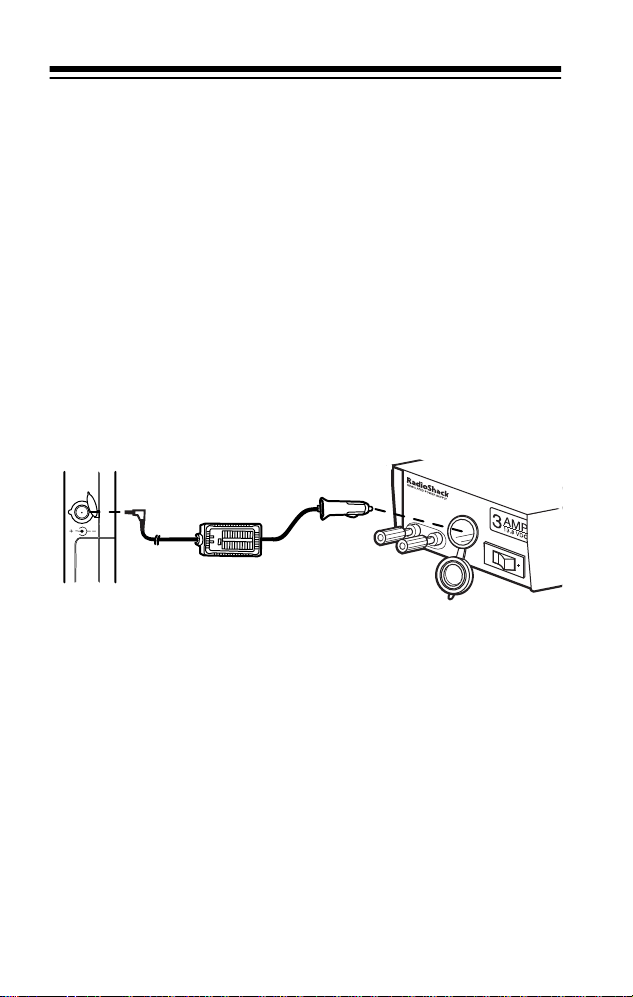
USING AC POWER
You can operate the HTX-200 from AC power using a regulated
power supply capable of supplying 13.8 VDC at least 1A and a
vehicle power adapter (see “Using Vehicle Battery Power” on
Page 12). The supply should also have an accessory power
socket into which the DC-to-DC power adapter fits. If your power
supply does not have an accessory power socket, you can either
wire the power cord directly to your power supply or add an accessory power socket to the supply. Suitable connectors, power
supplies, power cords, and sockets are available at your local
RadioShack store.
The following illustration shows how to connect a typical power
supply, a DC-to-DC power adapter, and the HTX-200.
RE
GUL
AT
ED
PO
W
ER
SU
PP
LY
AMP
3
13.8 VDC
USING NI-CD OR NI-MH BATTERY
POWER
You can use either Ni-Cd or Ni-MH batteries to power your HTX200; however, you cannot re charge th ese batte ries while they are
inside the HTX-200. You can use a separate external charger for
recharging the batterie s outside the radio. Your lo cal RadioSha ck
store carries a selection of suitable batteries and chargers.
As these batteries provide less voltage than that typically
Note:
supplied by alkaline batteries, expect less transmitting output
power when you use the HTX-200 with Ni-Cd or Ni-MH battery
power.
11
Page 12

USING VEHICLE BATTERY POWER
You can power the HTX-200 from a vehicle’s 12V power source
(such as cigarette-lighter socket) using an 9-volt, 900 mA DC-toDC power adapter and a size I Adaptaplug® (neither supplied)
with TIP se t to +. Both are available at your local RadioShack
store.
Cautions:
Y ou mu st use a pow er sourc e that supp lies 9V DC
and delivers at least 900 mA. Its center tip must
!
be set to positive and its plug must fit the HTX-
DC 9V
200's
these specifications could damage the HTX-200 or the
adapter.
• Always connect the DC adapter to the HTX-200 before you
connect it to the power source. When you finish, disconnect
the adapter from the power source before you disconnect it
from the HTX-200.
Follow these steps to operate the HTX-200 from a vehicle’s battery power.
1. Insert the Adaptaplug into the HTX-200’s
2. Plug the other end of the adapter into the cigarette-lighter
socket in the vehicle.
jack. Using an adapter that does not meet
jack.
DC 9V
12
Page 13
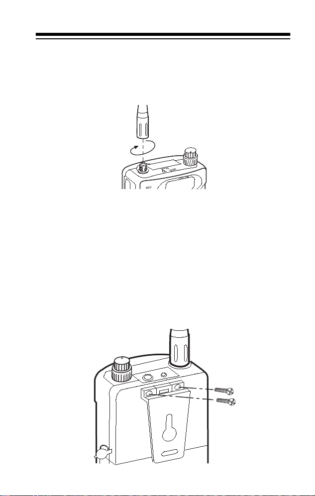
CONNECTING THE ANTENNA
Place the threaded ba se socket of the supp lie d an ten na over the
antenna connector on to p of the transc eiver and tu rn the antenna
clockwise to tighten it
. Turn it clockwise to remove it.
Caution:
Note:
an SMA-to-BNC adapter. This adapter, as well as suitable antennas, are available through your local RadioShack store.
Do not over-tighten the antenna
You can connect an external antenn a to the HTX-200 using
ATTACHING THE BELT CLIP
Use a Phillips screwdriver and the two supplied screws to attach
the supplied belt clip to your transceiver. Do not overtighten the
screws.
13
Page 14
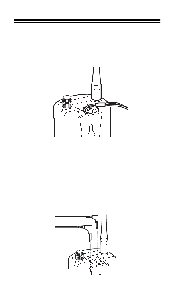
ATTACHING THE WRIST STRAP
To attach the supp lied wrist s trap to the top of the b elt clip, thread
the strap’s small loop through the opening in the top of the clip.
Then insert the longer loop through the smaller loop and pull on
the strap until the loop is tight.
CONNECTING A MICROPHONE/
SPEAKER
You can connect an external communications headset (consisting of a microphone and speaker) to the transceiver so you
can use it privately. Lift the hinged, rubber dust cover from the
and
MIC
the plug of an optional voice activated headset with microphone, or an optional communication headset, i nto t he j acks.
jacks on the top of the transceiver, then insert
SPK
14
Page 15
Caution:
not share a common gro und for the speaker and the m icrophone .
Doing otherwise might damage the transceiver.
Note:
ternal spea ker.
Use only microphone and speaker accessories that do
Inserting a head set’s plug automati cally disconnec ts the in-
You can also connect an optional mono earphone to the
jack. This lets you use the transceiver’s push-to-talk button to
transmit as usual. Your local RadioShack store carries a wide selection of suitable communications headsets, earphones, and
separate components.
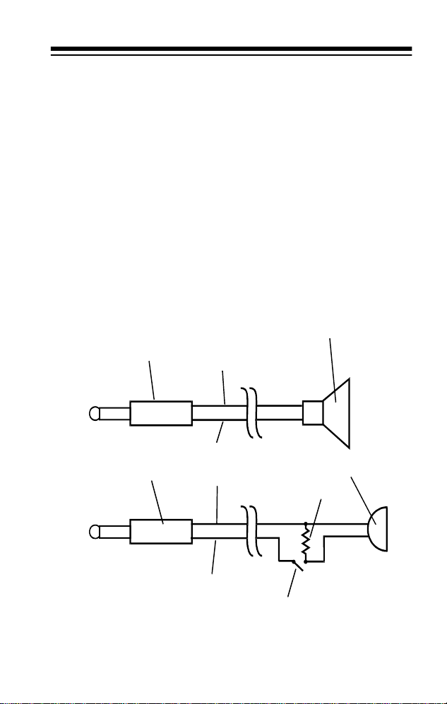
The following schematic diagram shows the typical wiring for a
suitable external mic and speaker.
External Speaker
Speaker Plug
Barrel
SPK
–
+
Tip
MIC Plug
Barrel
External Microphone
ΩΩΩΩ
22k
–
+
Tip
PTT
15
Page 16

USING THE MENUS
USING THE HTX-200’S MENUS
The HTX-200 provides two menus to access its features, the
Main Menu and the Tone Set Menu. To see details about each
operation, refer to the page number in the following chart.
To access the Main Menu, hold down
HTX-200. (The
option app ears). Hold down
CS
while turning on the
FUNC
FUNC
peatedly press W or V to step through the other options.
Release
Main Menu
Options
CS
Frequency
Step
bCLO
Busy Channel Lockout
t.dY
Transmit
Delay Time
Sd
Scan Delay
Time
and press V or W to change an option’s settings.
FUNC
Setting
( ) = default
setting Description Page
.0050
(MHz),
.0100
,
.0125, .0150
.0200
.0500, 1.000
(Off)
On
Off
(On)
1 to 30 seconds
(5)
.0250
, (
Sets the increment
for scanning the
band.
,
),
Prevents transmitting while receiving
a signal.
Prevents
squelch tail.
Sets the scanning
restart time.
then re-
39
41
41
32
16
Page 17

Main Menu
Options
Setting
( ) = default
setting Description Page
tot
Time out
Timer
PS
Power Save
rPt
Repeater
Offset
(Off)
On
10 – 990 seconds
(Off)
On
0.0
8.0
–
100kHz steps.
(0.6)
MHz in
Limits trans mit time. 40
Cycles power
(PS flashes) to the
receiver section to
conserve batteries.
The circuit remains
off then turns on
briefly to check for
an incoming signal.
Sets the offset in
100kHz steps
between the
repeater’s transmit
and receive frequencies.
40
27
17
Page 18

The Tone Set Menu lets you set featu res th at rel ate t o so und and
the CTCSS tones. To access these settings, turn on the HTX-200
then
hold down
pears.) Press
FUNC
and press
FUNC
+ V or W to select the opti on, the n V or W to
T.SET
. (The tone option ap-
change the setting.
Tone Set
Option
tone
Subaudible
Tone
rC
Receive
Tone
tC
Transmit
Tone
MEL
Tone Paging
Setting
( ) = default setting Description Page
(Off)
On
See the table
on Page 36.
(110.9)
See the table
on Page 36.
(110.9)
(1), 2, 3, 4, 5 Lets you select a
Lets the HTX-200
transmit and
receive the Subaudible Tone
(CTCSS) fre quencies so you
can listen only to
other units with
the same tone.
Lets you select
one of 47 different
receiving subaudible tones or
turn the feature
off
.
Lets you select
one of 47
different subaudible tones or turn
the feature off
tone to receive or
transmit.
.
35
35
35
37
18
Page 19

A QUICK LOOK AT THE CONTROLS
Most of the controls of t he H T X-200 hav e m ul tip le func tions. Use
the following chart to review the function of each control.
VOL/OFF
SQ
PTT
Speaker
Key/Control Use it to:
Microphone
Use with the
FUNC + Key to:
VOL/OFF
SQ
()
Turn the radio on/off.
Adjust the volume.
Set the squelch level to
block weak signals.
Change (increase) the
frequency by the value
set for
menu option on Page
16).
(see the first
CS
Access the Main
Menu.
N/A
Directly changes
the frequency, one
digit at a time.
Repeatedly press
V
to access each
digit of the displayed frequency.
19
Page 20

Key/Control Use it to:
Use with the
FUNC + Key to:
(T.SET)
MO (REV)
(BEEP)
MR (MW)
SC (RPT)
Change (decrease) the
frequency by the value
set for
menu option on Page
16).
Press to override
squelch. Press and
hold to cycle through
rC, tC, rPt
settings.
Turn on the display’s
backlight for 4 seconds.
Enter memory setting
mode.
used memory location
appear.
Starts and stops scanning. Hold down and
power on to access
expanded band coverage
(142–150 MHz).
(see the first
CS
, and CS
MR
and the last
Accesses the T one
Set Option menu
and settings.
Reverse the
repeater offset.
Enable/disable the
key tone.
appears when the
key tone is
enabled.
In memory mode,
starts the display
flashing. Then use
or to
access a frequency to store in
a memory location.
Set the radio to
simplex or duplex
mode when in
VCO mode. Set
the repeater offset
for a memory location when in memory mode.
20
Page 21

Key/Control Use it to:
Use with the
FUNC + Key to:
C (LOCK)
PTT
(Push To Talk)
Press once to display
and switch to the current call frequency.
Hold down to change
the call frequency and
associated parameters, such as repeater
offset and CTCSS
tones.
Hold down to transmit.
Press to store the settings.
Lock the controls
(except
VOL
Press again to
unlock the controls.
Swap the input
and output frequencies for
repeater operations.
,
PTT
, and SQ).
,
21
Page 22

A QUICK LOOK AT THE DISPLAY
1
2
3
4
5
6 7 8 9 10 11
1.F: appears when the
2.TX: appears when the radio is transmitting.
3.
4.
5. : indicates the battery strength.
6.
7.
8. : the stronger the signal, the more boxes appear.
9.
10.
11.MR (Memory Channel indicator): for use or for programming.
12. : paging tone active.
13. : key tone enabled.
14. : keypad control disabled to prevent accidentally
15.PS: appears when power save is enabled.
16.
17.ã: appears to indicate a positive repeater offset. – indicates a nega-
: appears when the radio receives a signal.
BUSY
: appears when tone squelch is on and the radio receives a
CALL
matching tone.
(Signal/RF Indicator): shows the level of an incoming signal.
S-RF
When transmitting, shows the relative output signal strength.
: appears when you turn on the radio — the signal strength
BAT
meter then indicates the battery strength.
Bars show remaining battery power when MO and
held down at the same time.
Alpha-Numeric Display
Memory Location
changing a setting.
: appears when Tone Squelch (CTCSS) is enabled.
TSQ
tive repeater offset.
: shows the memory channel in use.
key is pressed.
FUNC
: shows frequency and messages.
121314151617
PTT
switch are
22
Page 23

OPERATION
TURNING ON THE HTX-200
To turn on the HTX-200, rotate
The HTX-200 sounds a b rief melody if the k ey to ne fe ature is enabled. Then
used frequency appears.
HELLO
appears for about 2 seconds and the last
VOL/OFF
clockwise until it clicks.
SELECTING FREQUENCIES
(DIRECT TUNING)
You tune to the desired f requencies i n the VFO (variable frequency oscillator) mo de. You ca n either s tep to a s pecific frequenc y or
directly select the frequency.
To step to a frequency, repeatedly press or hold down
until the display shows the desired frequency.
The HTX-200 steps up or down in increments which you
Note:
set using the Frequency Step menu opti on. (See “Setting th e Frequency Step” on Page 39).
To directly enter a frequency, press
from the left flashes), then press or to change the number.
Press
each number of the desired frequency, then press
the selection.
Note:
and 174 MHz, and transmi t between 1 44 to 148 MHz. To expand
the frequency coverage, see “Changing the Transmit Frequency
Range” on Page 38.
+ again to select the next digi t. Repeat this to s elect
FUNC
The HTX-200 is preset to receive frequencies between 136
+ (the second digit
FUNC
PTT
or
to store
23
Page 24

RECEIVING TRANSMISSIONS
Follow these steps to receive standard transmissions.
1. With the radio on, rotate
a hissing sound. Then slowly rotate
the noise stops.
Notes:
•
• Volume, po wer , an d squelch are combined in on e c ontro l.
• If the HTX-200 picks up unwanted, weak transmissions,
2. Set
appears when the HTX-200 receives a standard
BUSY
transmission or if the squelch is open. If the transmission
uses CTCSS tones,
The inner control is
the outer control is
rotate
for these transmissions. If you want to hear weak transmissions, rotate SQ counterclockwise. When you do this,
you might hear hissing between transmissions.
VOL/OFF
clockwise to prevent the squelch from opening
SQ
to a comfortable listening level.
counterclockwise until you hear
SQ
clockwise just until
SQ
also appears.
CALL
(volume) and power on/off, while
VOL
(squelch).
SQ
TEMPORARILY OPENING SQUELCH
If you use the Tone Squel ch (CTCSS) featu re, you might not h ear
a trans
mission on the current fre quenc y. T
squelch so you ca n hear a ll trans mission s o n the freq uency , hold
down
. To resume normal operation, release MO.
MO
o temporarily open t he
24
Page 25

TRANSMITTING
There are two basic types of communication possible with this
transceiver: radio-direct-to-radio (simplex) or radio-to repeaterto radio (duplex). Simplex operation uses the same frequency
to send and receive. Duplex operation uses one frequency to
transmit and another to receiv e. For more in formation about duplex, see “Understanding Repeaters” on Page 26.
Caution:
Technician Class licen se is sued by the FCC.
Follow these steps to transmit.
1. Select the desired frequency usin g manual or direct entr y.
2. Hold the HTX-200 about 3 inches from your mouth.
3. Hold down
4. Release
It is illegal to transmit if you do not have at least a
, then speak slowly and clearly into the
PTT
microphone.
If you try to transmit outside the transmit frequency
Note:
range,
inhibit
appears while you transmit.
TX
briefly appears.
when you finish transmitting.
PTT
25
Page 26

UNDERSTANDING REPEATERS
Operation through a repeater, where you transmit on one frequency and recei ve on a nother , is ca lled
ation direct to a nother station , wh ere yo u tr ansmit a nd receive on
the same frequency, is called
A repeater is a station that receives a signal on one frequency
input
(the
ent frequency (the
ically located at the tops of tal l building s or on antenna tow ers, so
a relatively low-po wer s ig nal ca n re ac h th e re pea ter. The repeater retransmits th e sig nal a t a h igher power . This gives your transceiver the ability to communicate over a much greater range.
To use a repeater, you m ust kno w the rep eater’s input an d output
frequencies. Repeaters are usually identified by their output frequency. Thus, a repeater that has an output frequency of 146.94
is referred to as “the 146.942 repeater.” To determine the input
frequency, you mu st know the frequency
for the 2-meter band) and the
kHz to the output, or – if you subtract 600 kHz from the output).
Whether the offset is positive or negative depends on:
frequency) and then retransmits that signal on a differ-
output
• which part of the band the repeater operates on
• local convention
• proximity of repeaters using the same two frequencies
simplex
frequency). Repeater ant ennas are typ-
offset direction
duplex
operation.
offset
(+ if you add 600
operation. Oper-
(typically 600 kHz
To determine the offset and the direction, obtain a copy of
ARRL Repeater Handbook
dioShack store or directly from the ARRL) which lists the locations of repeaters as well as their frequency and offset
information.
above the displayed frequency indicates a positive offset,
A
+
while a – above the frequency indicates a negative offset. If neither
26
or – appears, the HTX-200 is set for simplex operation.
n
+
(available from your local Ra-
The
Page 27

SETTING THE REPEATER OFFSET
FREQUENCY
The HTX-200’s default re peater o ffset is 6 00 kHz , which a ppears
as
0.6
Note:
quency offset in a memory, that setting is not affected.
1. With power off, hold down
2. Hold down
current offset
set.
3. Repeatedly press or until the desired offset appears.
You can set an offset between 0 and 8 MHz in 100kHz
steps.
4. Press
)
. Follow these steps to change the offset.
(MHz
This setting on ly aff ect s the VFO mode. If yo u s av ed a fre-
and turn on the HTX-200,
FUNC
and repeatedly press until
FUNC
appear.
to store the setting and exit the menu.
PTT
appears if no offset is currently
0.0
rpt
and
the
TURNING DUPLEX
OPERATION ON AND OFF
To turn on duplex (repeater use) operation for the VFO mode,
press
ue is not
appears above the displayed frequency. Press
again to turn it off.
FUNC
0.0
+ SC (
, the current offset indicator (+ above or – below)
). Provided the current repeater offset val-
RPT
+ SC (
FUNC
RPT
27
)
Page 28

SETTING THE REPEATER OFFSET
DIRECTION
1. Set an offset frequency other than 0.0.
2. Press
above or
3. Press
tion.
FUNC + SC (RPT)
below).
–
+ MO (
FUNC
to see the current offset direction (
) to change the repeater offset direc-
REV
+
To save this setting in a memory location, must be
Note:
flashing before you store the settings (see “” on Page 31 and
“Storing a Transmit/Rec eive Frequency” on Pa ge 29). Otherwise,
the setting revert s to its saved v alue the next time you turn on the
HTX-200.
MR
REVERSING THE TRANSMIT AND
RECEIVE FREQUENCIES
To swap the input and output frequencies, press
example, if you have set the radio to repeater operation on
146.940 wit h a positive of fset, the r adio would normally rec eive
on 146.94 and transmit on 146.340 MHz. After you press
FUNC+PTT,
146.940.
This feature is useful if you want to determine whether you are
close enough to anoth er station to commun icate on a simplex fre quency. While the other station is transmitting, reverse the frequencies. If you can still hear the other station, you are hearing
their signal directly and you do not need to use the repeater.
the radio will receive on 146.340 and transmit on
FUNC+PTT
. For
28
Page 29

MEMORY OPERATION
Your HTX-200 has 30 standard memory locations that you can
use to store frequenci es for quick acc ess. For each memory loca tion, you can also store ot her settings such as the repeater offset ,
CTCSS tones, and frequencies to pass or lock out during scanning.
STORING A TRANSMIT/RECEIVE
FREQUENCY
1. Press
2. Repeatedly press or to select the desired memory
location.
3. Press
flash.
4. Select the desired frequency by repeatedly pressing
or , or use direct frequency entry to select a frequency.
5. To enter a frequency offset for repeater operation, press
FUNC
calling frequency. Then press or to select the desired
offset. Press
6. Press
remove an offset for simplex operation, set the repeater offset to
7. If desired, set the tone squelch settings (see “Continuous
Tone Coded Squelch System Features” on Page 35).
8. Press
memory mode.
MR
and the last used memory location appear.
.
MR
appears if the memory location is empty.
------
FUNC+MR
+ SC. The HTX-200 displays the current offset for the
FUNC
0.0
PTT
. The selected memory location and
to store your setting.
PTT
+
to select the offset direction (+ or –). To
REV
.
to store all settings, then press MR to exit the
MR
29
Page 30

RECALLING MEMORIES
To recall saved memory settings, press MR so appears. Then
MR
press or to select the desired memory location.
Press MR again to return to the VFO mode. (See “Selecting Fre-
quencies (Direct Tuning)” on Page 23.)
CLEARING A SINGLE MEMORY
Follow these steps to clear any single memory location.
1. Press
2. Repeatedly press or to select the desired memory
location.
3. Press
flash.
4. Hold down
clears and
empty.
5. Press MR to exit the memory mode.
To clear all memory loca tions, see “Resetting the HTX-
Note:
200” on Page 44.
MR
. and the last used memory location appear.
MR
FUNC+MR
. The selected memory location and
for several seconds. The memor y loca tion
FUNC
appears to confirm that the location is
------
MR
30
Page 31

USING THE CALLING-FREQUENCY
MEMORY
The calling-freque nc y memory location l ets y ou quickly jump to a
specific frequency at any time. The default calling frequency is
146.52 MHz. You can store a differe nt frequen cy into m emory as
well as other settin gs as soci ated wi th that fre quenc y, suc h as the
repeater offset and CTCSS tone.
1. Press
2. To change the frequency, hold down
to display the current calling frequency.
C
until and C flash.
C
MR
3. Select a frequency. See “Selecting Frequencies (Direct Tuning)” on Page 23.
4. Press
to store the selected frequency in memory.
C
5. To enter a frequency offset for repeater operation, press
FUNC+SC
. The HTX-200 displays the current offset for the
calling freq uency. To select a new offset value, press or
. Select 0.0 Hz if you want to remove the offset. To store
the setting, press
6. To select the offset direction (+ or –), press
PTT
.
FUNC + REV.
To
remove an offset for simplex operation, set the repeater offset to
0.0
.
While and
Note:
MR
C
appear, you can program other settings such as CTCSS tones (see “Continuous Tone Coded
Squelch System Features” on Page 35.)
To enable the calling frequency, press
at any time. The trans-
C
ceiver immediately tunes to that frequency with the settings you
programmed. To exit the calling frequency mode, press
again.
C
31
Page 32

SCANNING OPERATION
SCANNING FOR ACTIVE FREQUENCIES
1. To search for activity on a frequency, press SC. The transceiver begins to scan up or down the full frequency range,
and it stops on each active frequency for the duration set by
the scan delay option (see “Using Scan Delay” on Page 32).
2. To change the scanning direction, press or .
3. To stop on a frequency or to stop scanning completely,
SC
again.
press
Using Scan Delay
If the HTX-200 stop s on a signal during scannin g, then
stops, the scan de lay fe ature de lays the co ntinua tion of scann ing
to allow time for the signal to restart. Access t he Main Men u (see
“Using the HTX-200’s Menus” on Page 16) to set the value. With
Sd
and the current delay time s hown,
new delay time (between 1 and 30 seconds).
press or to select the
that signal
SCANNING STANDARD MEMORY
LOCATIONS
1. Press
2. To change the scanning direction, press or .
3. To stop scanning, press
32
MR
scans all locations except empty locations and the ones you
programmed to be passed during scanning.
MR
appears), then press SC. The transce iver
(so
again.
SC
Page 33

Setting A Memory Location to Always Skip
During Scanning
The HTX-200 is preset to include all memory locations (except
empty locations) during memory scanning . Follow these steps
to set the transceiv er to ha ve it a lways skip (or resum e sc anning )
a specific location during scanning.
MR
1. Press
2. Repeatedly press or to select the desired memory
location.
3. Press
flash.
4. To set the HTX-200 to skip the memory location, press
then press or so
. and the last used memory location appear.
MR
FUNC+MR
. The selected memory location and
SCSP ON
(scan skip) appears.
MR
SC
,
To include the displayed location during scanning, press
or so
SCSP oF
5. When yo u fini sh, pre ss SC again, then press
appears.
to store the
PTT
setting.
33
Page 34

Temporarily Locking Out (Skipping) Locations
During Memory Scanning
You can set the transceiver to lock out a location while scanning
the frequencies stored in memory.
When the transceiver stops at a memory location you want to
PASS
FUNC
.
skip, press
tinues to scan, locking out (skipping) that location from then on.
Repeat this for each location you want to skip.
To cancel the settings a nd have the HTX-200 inc lude th e skipp ed
frequencies once again, turn the radio off then on again.
You cannot lock out all memory locations. One location is
Note
:
always active. If you l ock ou t all bu t two acti ve loc ation s and th en
lock out one more,
briefly appears a nd the transceiver c on-
EMPTY
briefly appears and scanning stops.
34
Page 35

CONTINUOUS TONE CODED
SQUELCH SYSTEM FEATU RES
Your HTX-200 can transmit and receive a low-level, selectable
subaudible tone at th e s ame tim e a s i t tran sm its (TX) o r rec eiv es
(RX) a regular signal. This speci al ton e lets you lis ten on ly to other radios set to the same tone frequency when y ou us e the HTX200 in simplex operation. It also lets you match your radio to the
subaudible tone frequency used by a local repeater.
To enable the TX and RX tones for the HTX-200, follow these
steps.
1. Press
tone on
or
2. Press or to turn on the option .
+ . The current tone setting appears (
FUNC
).
tONE on
tONE oF
appears
.
3. To set a receive (RX) tone, press
Then press or to select a tone frequency from the list
on Page 36.
both the transmit and receive frequencies.
4. To set a transmit (TX) tone, press
Then press or to select a tone frequency from the list
on Page 36.
5. Press
For this example, 67.0 MHz was selected for
to store all the settings.
PTT
+. rC appears.
FUNC
+. tC appears.
FUNC
35
Page 36

To select and store a CTC SS subaudible tone in a mem ory loc a-
MR
.
tion, press
MR
and the last used memory location appear.
(In the examples sho wn on the pre cedin g page , memo ry loc ation
2 is used.) Then follow the preceding Steps 1–5.
Subaudible Tone Frequencies (Hz
)
67.0 114.8 186.2
69.3 118.8 189.9
71.9 123.0 192.8
74.4 127.3 196.6
77.0 131.8 199.5
79.7 136.5 203.5
82.5 141.3 206.5
85.4 146.2 210.7
88.5 151.4 218.1
91.5 156.7 225.7
94.8 159.8 229.1
97.4 162.2 233.6
100.0 167.9 241.8
103.5 173.8 250.3
107.2 179.9 254.1
110.9 183.5 Off
36
Page 37

TONE PAGING
You can set the HTX-20 0 t o s oun d an alert tone when it rec eiv es
a transmission th at inc ludes the c urrentl y se t suba udible rece ivetone (or any transmission, if the receive-tone or the tone feature
is set to off). Turn off the radio, then press while you turn the
HTX-200 on again. appears.
The first time the HTX-200 receives a transmission that matches
the current CTCSS settings, it sounds the selected alert tone,
then turns off the tone paging feature. To turn the featur e back on,
turn the power off then on again while holding down .
Follow these steps to change the alert tone.
1. Select the VFO mode. (See “Selecting Frequencies (Direct
Tuning)” on Page 23.)
2. Hold down
number from
3. Repeatedly press either or to step through the five different tones. If key tone is enabled, each tone sounds as
you select its number.
4. Press
PTT
and press (
FUNC
to 5 appear. Release
1
to store your selection and exit the menu.
T.SET
) four times.
.
FUNC
MEL
and a
SENDING PAGING TONES
To transmit the selected paging tone, press
PTT
.
while pressing
37
Page 38

OTHER SPECIAL FEATURES
CHANGING THE TRANSMIT FREQUENCY
RANGE
You can change the standard transmit frequency range from
144–148 MHz to an extended range of 142–149.885 MHz.
To set the transceiv er to its extended ra nge, turn off the tra nsceiver, then hold down
To return to the standard frequency range, turn off the transceiver, then hold down SC and turn it on again.
Transmitting out of the normal band is allowed only for
Note:
MARS (Military Amateur Radio Service) and CAP (Civilian Air Patrol) operators. You must have the appropriate license.
LOCKING THE KEYPAD
To lock the transceiver’s keypad so you do not accidentally
change a setting, press
buttons except
and turn on the transceiver again.
SC
PTT
FUNC+LOCK
VOL
, ,
, and SQ.
. appears. This loc ks all
To unlock the keypad, press
FUNC
+
LOCK
again.
LIGHTING THE DISPLAY
Press to turn on the display’s backlight for about 4 seconds. If
you press any key while the light is on, the light remains on for
about 4 seconds more. Hold down for at least 1 second to hav e
the light remain on until you press again.
38
Page 39

TURNING THE KEY TONE ON AND OFF
The transceiver is preset to sound a beep each time you press a
key. To turn off the beep, pr ess
To restore the key tone, press
Note
: If the key tone feature is disabled, the power-on tone does
not sound.
FUNC
FUNC
+ (
+ (
BEEP)
. disa ppears.
BEEP
) again.
CHECKING THE CURRENT MEMORY
SETTINGS
If you hold down MO (
opens and the set valu es for receive tone (
tone (
tt on/off
offset (
rPt
Release
MO (REV
), scan skip co ndition (
), and frequency step (CS) appear.
) to turn on the squelch again.
) for longer than 1 second, the squelch
REV
rT on/off
)(if any), repeater
SCSP
), transmit
SETTING THE FREQUENCY STEP
To change the frequency increment used during scanning and
stepping to a frequency , use the Main Men u to access the CS op tion setting (see “Using the HTX-200’s Menus” on Page 16). Then
repeatedly press or until you reach the desired settin g. You
can change the frequency step to 5 kHz, 10 kHz, 12.5 kHz, 15
kHz, 20 kHz, 25 kHz, 50 kHz, or 1 MHz. (The example shown
here is 25 kHz.)
39
Page 40

POWER SAVE
The power save feature lets the radio conserve battery power by
turning off power to the receiver section and periodically turning
it on to check for a transmission. Use the Main Menu to set the
power save option (see
With PS and the curre nt sta t us (on or
16).
or to turn this feature on or off.
“Using the HTX-200’s Menus” on Page
oFF
) displayed, press
TIME-OUT TIMER
When you communicate using repeaters, keep your transmissions as brief as possible. Most repeat ers have built-in tim ers that
limit single transmissions to 3 minutes or less. You can set the
transceiver to stop transmitting and sound a beep if you exceed
a set time limit with a single transmission.
Use the Main Menu (see “Using the HTX-200’s Menus” on Page
16) to set a value fo r the ti me-ou t time r. With
setting displayed, press or to choose a value from 0 to 990
seconds.
tot
and the current
40
Page 41

REDUCING SQUELCH TAIL
If you are communicating with a repeater or an other stat ion using
subaudible tones, you can eliminate the squelch tail (the burst of
noise the other person hears wh en you stop transmitt ing) by turning on the transmit delay option. When you turn on this feature
and use CTCSS, the radio continues to transmit for a sho rt period
of time after you release
subaudible tone. This causes th e other radio to close the sq uelch
before there is “dead air,” preventing the squelch tail.
Use the Main Menu (see “Using the HTX-200’s Menus” on Page
16) to set the transmit delay option. Then , with
rent status displayed, press or to turn this feature on or off.
, but then it immediately drops the
PTT
t.dy
and the cur-
BUSY CHANNEL LOCKOUT
Use the Main Menu to set the busy channel lockout (see “Using
the HTX-200’s Menus” on Page 16). The lockout prevents the
transceiver from transmitting while it is receiving a signal. With
the radio’s preset value
change the display to
display back to
bCLO
bCLO oF
bCLO
oF
to disable the lockout .
displayed, press or to
oN
. Repeat this step to change the
41
Page 42

TROUBLESHOOTING
If your transceiver is not working as it should and it displays an
error message, these suggestions might help you eliminate the
problem. If the transceiver still does not operate properly, take it
to your local RadioShack store for assistance.
You see Possible Cause Remedies
S-SHORT
PLL-Error
EEP-Error
If the transceiver
detects a shorted
external microphone
connection, it automatically s witches off
power to the audio
amplifier and dis-
S-SHORT
plays
indicate a short circuit.
Indicates a PLL circuit malfunction due
to a defect in the
VCO circuit or bias
supply.
The EPROM information needs to be
reset.
to
Remove the connected microphone and
replace it, or use
the internal microphone.
Turn power off
then on again.
Reset the transceiver. See
“Resetting the
HTX-200” on
Page44.
42
Page 43

CARE AND MAINTENANCE
Your RadioShack HTX-200 Mini Handheld Two-Meter FM Amateur Transceiver is an example of superior design and craftsmanship. The following suggestions will help you care for your
transceiver so you can enjoy it for years.
Keep the transceiver dry. If it gets wet, wipe it dry
immediately. Liquids might contain minerals that
can corrode the electronic circuits.
Use and store the transceiver only in normal temperature environments. Temperature extremes
can shorten the life o f el ec tron ic dev ic es , da ma ge
batteri es, and distort or melt pl astic parts.
Keep the transceiver away from dust and dirt,
which can cause premature wear of parts.
Handle the transcei ver ge nt ly an d caref ul ly. Dro pping it can damage circuit boards a nd cases and
can cause the transceiver to work improperly .
Use only fresh batteries of the required size and
recommended type. Batteries can leak chemicals
that damage your transceiver’s electronic parts.
Wipe the transceiver with a damp cloth occasionally to keep it looking new. Do not use harsh
chemicals, cleaning solvents, or strong detergents
to clean the transceiver.
Modifying or tampering with the transceiver’s internal components can cause a malfunction and might invalidate its warranty
and void your FCC authorizat ion to opera te it. If your transcei ver is not performing as it should, take it to your local RadioShack store for assist ance.
43
Page 44

USING THE KEYPAD DIAGNOSTIC
The HTX-200 has a bu ilt-in diagnostic p rogra m tha t l ets y ou c onfirm whether the keypad switches are functioning correctly. To
use this diagnostic program, follow these steps.
1. Hold down
2. Press
3. Press . If the action is correct,
4. Press . If the action is correct,
5. Press
6. Press
7. Press
appears.
8. Press
9. Press
10. Press
briefly and then the set frequency appears again.
MO (REV
MO (REV
MR (MW)
SC (RPT)
(BEEP)
LOCK (C)
. If the action is correct,
FUNC
MO (REV)
) and turn on the transceiver.
) again.
. If the action is correct,
. If the action is correct,
. If the action is correct, F appears.
PrESS dn
. If the action is correct,
. If this action is correct,
appears.
PrESS Up
PrES Mr
PrESS Sc
PrESS bp
PrES Mo
appears.
appears.
appears.
GOOD
appears.
appears.
PrESS Lc
appears
RESETTING THE HTX-200
If the transceiver’s display locks up or the transceiver does not
work properly after you turn it on, you might need to reset it.
Caution
grammed into the transceiver. Before you reset the transceiver,
try turning it off th en o n a gai n t o s ee if i t begins working properl y.
: This procedure clears all the information you have pro-
To reset the transceiver, turn it off then hold down
turn it on again.
tion. Release
44
iniTial
FUNC+MO
appears to confirm the reset opera-
.
FUNC +MO
and
Page 45

SPECIFICATIONS
GENERAL
Frequency:
RX .............................................................. 136–174 MHz
TX ............................................................... 144–148 MHz
Extended Range......................................... 142–150 MHz
Frequency Generation .............................. PLL Synthesizer
Frequency Stability ................................................ ± 5 ppm
Operating Temperature ......... 14° to 131° F (–10° to 55° C)
Power Source ............................................... DC 3.0V to 9V
Modulation .................................................................... F3E
Impedance .............................................. ...... .......... 50 ohm
Dimensions (HWD) ....................... 2
85 × 58 × 26.5 mm
Weight (without batteries) ............................. 4.2 oz (120 g)
RECEIVER
Circuit Type ................. Dual Conversion, Superheterodyne
IF Frequency:
1st IF ................................................................ 30.85 MHz
2nd IF ................................................................... 450 kHz
Sensitivity ........................................ 0.22 µV for 12 dB SND
Selectivity ........................................................... 50 dB Min.
Spurious and Image Rejection ........................... 60 dB Min.
Intermodulation .................................................. 60 dB Min.
Distortion ............................................................ 10% Max.
S/N Ratio ........................................................... 35 dB Min.
Audio Output @10%THD ................... 90 mW 16 Ohm, BTL
1
/4 × 33/8 × 11/16 inches
TRANSMITTER
Power Output .................... 200 mW, DC 3.0V/2W, DC 9.0V
Distortion ....................................................................... 5%
Deviation ................................................................. ± 5 kHz
S/N Ratio ................................................................... 36 dB
Current Drain ..................... 600 mA, DC 3V/900mA DC 9V
Specifications are typical; individual units might vary. Specifications are subject to change and improvement without notice.
45
Page 46

NOTES
46
Page 47

47
Page 48

Limited One-Year Warranty
This product is war ranted by RadioShac k against manufactu ring defects in
material and workmanship under normal use for one (1) year from the date of
purchase from RadioShack company-owned stores and authorized RadioShack franchisee s and dealers. EXCEPT AS PROVIDE D HEREIN, RadioShack MAKES NO EXPRESS WARRANTIES AND ANY IMPLIED
WARRANTIES, INCLUDING THOSE OF MERCHANTABILITY AND FITNESS FOR A PARTICULAR PURPOSE, ARE LIMITED IN DURATION TO
THE DURATION OF THE WRITTEN LIMITED WARRANTIES CONTAINED
HEREIN. EXCEPT AS PROVIDED HEREIN, RadioShack SHALL HAVE NO
LIABILITY OR RESPONSIBILITY TO CUSTOMER OR ANY OTHER PERSON OR ENTITY WITH RESPECT TO ANY LIABILITY, LOSS OR DAMAGE
CAUSED DIRECTLY OR INDIRECTLY BY USE OR PERFORMANCE OF
THE PRODUCT OR ARISING OUT OF ANY BREACH OF THIS WARRANTY, INCLUDING, BUT NOT LIMITED TO, ANY DAMAGES RESULTING
FROM INCONVENIENCE, LOSS OF TIME, DATA, PROPERTY, REVENUE,
OR PROFIT OR ANY INDIRECT, SPECIAL, INCIDENTAL, OR CONSEQUENTIAL DAMAGES, EVEN IF RadioShack HAS BEEN ADVISED OF
THE POSSIBILITY OF SUCH DAMAGES.
Some states do not allow the limitations on how long an implied warranty
lasts or the exclusi on of incide ntal or con sequenti al damage s, so the a bove
limitations or exclusions may not apply to you.
In the event of a pro duct de fect dur ing the w arra nty per iod, take the produ ct
and the RadioShack sales receipt as proof of purchase dat e to any RadioShack store. RadioShack will, at its option, unless otherwise provided by
law: (a) correct th e defect b y product r epair w ithout char ge for pa rts and la bor; (b) replace th e p ro duct w ith on e o f t he sam e o r simi lar d esign; or (c) refund the purchase price. All replaced part s and products, and produ cts on
which a refund is made, become the property of RadioShack. New or reconditioned parts and products may be used in the performance of warranty service. Repaired or replaced parts and products are warranted for the
remainder of the original warranty period. You will be charged for repair or replacement of the product made after the expiration of the warranty period.
This warranty does not cover: (a) damage or failure caused by or attributable
to acts of God, abuse, accident, misuse, improper or abnormal usage, failure
to follow instruction s, improper installation or m aintenance, alteration, l ightning or other incidence of excess voltage or current; (b) any r epairs other
than those provided by a RadioShack Authorized Service Facility; (c) consumables such as fuses or batter ies; (d) cosmetic damage; (e) transpo rtation, shipping or insu ra nce co sts; o r (f ) cos ts of p rod uct r em ova l, insta l lation ,
set-up service adjustment or rei nstallation.
This warranty gives you specific legal rights, a nd you may also have othe r
rights which vary from state to state.
RadioSha ck Customer Relations, 200 Taylor Street, 6th Floor,
Fort Worth, TX 76102
We Service Wh at We Sell
04/99
06A99 Printed in Korea
 Loading...