

Page 1
49-2512.fm Page 1 Wednesday, January 19, 2000 4:40 PM
B/W 1/3-INCH BASIC CCD CAMERA
Your RadioShack B/W 1/3-Inch Basic
CCD (Charge-Coupled Device) Camera is an important addition to your security system. While designed
primarily for use with the RadioShack
B/W 9-Inch 4-Channel Sec urity Monitor (Cat. No. 49-2511), you can also
connect it to a standard TV/monitor.
The camera includes a 65-foot cable
to provide extra flexib ility in your system. The CCD camera provides supe rior 78° wide pict ures even in low- light
conditions, and it includes a microphone so you can hear sound from the
area around the camera.
Warning:
This camera is not waterproof. To reduce the risk of electric
shock or damage, do not expose this
camera to rain or moisture.
FCC INFORMATION
This equipment comp lies with the limits for a Class B digital device as specified in Part 15 of
limits provide reasonable protection
against radio and TV inte rference in a
residential area.
However, your equipment might cause
TV or radio interferen ce even when it
is operating properl y. To elimin ate interference, you can try o ne or mor e of
the following corrective measures:
FCC Rules
. These
• reorient or relocate the receiving
antenna
• increase the distance between the
equipment and the radio or TV
• use outlets on different electric al circuits for the equipment and the radio
or TV
Consult your local Radi o Shack store if
the problem still exists.
: You must use shielded interface
Note
cables with this equipment.
WARNING:
shock hazard, do not expose this product to rain
or moisture.
CAUTION:
ELECTRIC SHOCK, DO NOT REMOVE
COVER OR BACK. NO USER-SERVICEABLE PARTS INSIDE. REFER SERVICING
TO QUALIFIED PERSONNEL.
!
Cat. No.
To reduce the risk of fire or
CAUTION
RISK OF ELECTRIC SHOCK.
DO NOT OPEN.
TO REDUCE THE RISK OF
This symbol is intended to alert
you to the presence of uninsulated dangerous voltage within
the product’s enclosure that might
be of sufficient magnitude to constitute a risk of electric shock. Do
not open the product’s case.
This symbol is intended to inform
you that important operating and
maintenance instructions are
included in the literature accompanying this product.
49-2512
!
RadioShack is a registered trademark used by Tandy Corporation.
©
1999 Tandy Corporation.
All Rights Reserved.
Page 2
49-2512.fm Page 2 Wednesday, January 19, 2000 4:40 PM
MOUNTING GUIDELINES
Before you mount and connect the camera, carefully plan where you will position the camera and r oute th e cable t hat
connects the camera to the monitor.
Keep in mind the following when planning the installation.
• This system is designed for indoor
use only.
• Do not install the camera where it
will be exposed to high humidity or
rain.
• Select a location fo r the camera so
you will have a clear view of the
area you want to monitor. Be sure
the location is free from dust, and
not in a direct line-of-sight with a
light source or in direct sunlight.
• Do not route the cable close to pow er or telephone lines, transformers,
or other electrical equipment that
could interfere with your security
system or with other sys tems or devices.
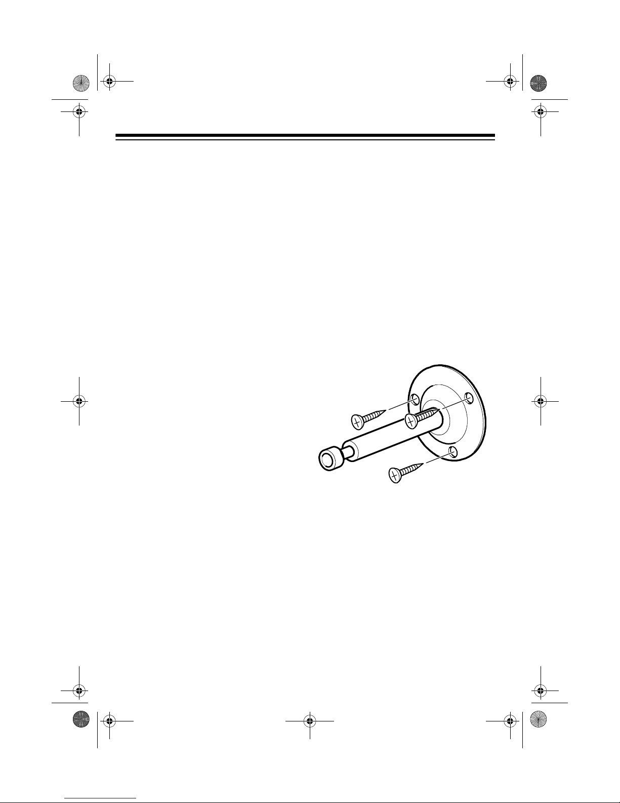
MOUNTING THE CAMERA
The supplied swivel-ball joint post assembly is des igned to let you mount th e
camera on a wood surface. If you plan to
mount the camera on a differ ent type of
surface, purchase appropriate hardware at your local hardware store. Obtain mounting hardwar e that will s upport
at least 10 pounds (4.5 kg), which includes the weight of th e camera and the
cable assembly.
Follow these steps to mount the cam era
using the supplied post assembly.
• Select a location for the camera that
has an ambient temperature between 14° and 113°F.
• If you plan to i nstall t he camer a in a
location that has conditi ons not recommended in this manual, consult
with a professional installer and consider use of a s epa r ate ca mer a c ov er or housing.
1. Loosen the locking knob and remove the ball joint assembly from
the top of the lock bolt.
2. Using the base of the post assembly
as a guide, mark the locations on
the mounting surface for the three
supplied wall screws.
3. Drill a starter hole at each marked
location.
4. Thread the screws through the
holes in the base an d into the holes
in the mounting surface. Tighten
each screw until the flange is secure.
2
Page 3

!
49-2512.fm Page 3 Wednesday, January 19, 2000 4:40 PM
5. Be sure the lock bolt is tig ht. Th read
the short,
1
/4-20 post on the ball joint
assembly into the camer a's threaded mounting hole. D o not overtighten it.
Locking Kn ob
1
/4-20 Post
Ball Joint Assembly
Lock Bolt
6. Place the camera/ball joint assembly over the top of the lock bo lt then
swivel/rotate the camera as needed.
(You might need someone to watc h
the TV or monitor to confirm the
camera’s position onc e you connect
the camera to your monitor, as
some small adjustm ent might be required.) Then tighten the locking
knob only enough to secure the
camera. Do not overtighten it.
CONNECTING TO A
STANDARD TV/MONITOR
You can connect the camera to a TV/
monitor that is equipped with audio/video input jacks. Follow these steps to
connect the camera.
: For the best results, mount the
Note
camera securely before connecting the
cable.
1. Connect the yellow
the supplied cable to the TV/monitor’s video input jack. See “Typical
Connections Overview” on Page 5.
2. Connect the cable’s white
plug to the TV/monit or’s audio i nput
jack.
3. Insert the supplied AC adapter’s
barrel plug int o th e re ce ptacle of the
cable’s DC12V jack. Then connect
the adapter to a standard AC outlet.
Caution:
You must use a
Class 2 power source that
supplies 12 volts DC and
delivers at lea st 200 mA. Its center
tip must be set to positive and its
plug must fit the CCD camera's
power cable jack. The supplied
adapter meets these spec ifications.
Using an adapter that does not meet
these specifications could damage
the CCD camera or the adapter.
VIDEO
plug of
AUDIO
4. Connect the 4-pin k eyed cable plug
into the matching socket on the
back of the camera.
The plug fits only one way. If it
Note:
does not immediately fit, do not
force it! Turn it over and try again.
3
Page 4

49-2512.fm Page 4 Wednesday, January 19, 2000 4:40 PM
CONNECTING TO A
4-CHANNEL SECURITY
MONITOR
To connect the camera to a RadioShack
4-Channel Security Monitor, see the
monitor’s owner's manual for complete
installation and operating instructions.
CARE
To enjoy your B/W 1/3-Inch Basic CCD
Camera for a long ti me:
• Keep the camera dry. If it gets wet,
wipe it dry immediately.
• Use and store the camera only in
normal temperature environ men ts .
• Handle the camera gentl y and carefully. Don’t drop it.
• Keep the camera away from dust
and dirt.
SPECIFICATIONS
Video Receptor .............. B&W 1/3” CCD
Receptor Resolution ...... 270,000 pixels
Video Resolution: More than 380 lines
Minimum Required
Illumination ............................. 0.2 LUX
AGC ............................. ....... ...... Built in
Lens ............... 4.3mm F/1.8 fixed focus
Angle of View ................................. 78°
Dimensions
(HWD) ............ 2
Weight ....................................... 1.7 oz
Specifications are typical; individual
units might var y. Specifi cations a re subject to change and im provement wi thout
notice.
1
/8 × 21/8 × 121/
(54 × 54 × 42 mm)
32
Inches
(50 g.)
• Wipe the camera with a da mp cloth
occasionally to keep it looking new.
Modifying or tampering with the camera’s internal components can cause a
malfunction and invalidate its warranty.
If your camera is not performing as it
should, take it to you r local RadioShac k
store for assistance.
4
Page 5

49-2512.fm Page 5 Wednesday, January 19, 2000 4:40 PM
TYPICAL CONNECTIONS OVERVIEW
Camera
Supplied Cable
Camera
TV/Monitor
A/V Input Jacks
Video (Yellow)
Audio (White)
AC Adapter
DC12V Jack
9-Inch Security Monitor Cat. No. 49-2511
Supplied Cable
Video (Yellow)
Audio (White)
Cable Supplied
with Cat. No. 49-2511
Mini-DIN Jack
DC12V Jack
5
Page 6

49-2512.fm Page 6 Wednesday, January 19, 2000 4:40 PM
Limited Ninety-Day Warranty
This product is warrante d by RadioShack aga inst manufact uring defects in mate rial and workma nship under normal u se for nine ty (90) days from the date o f purchase fro m RadioShack companyowned stores and authorized RadioShack franchisees and dealers. EXCEPT AS PROVIDED
HEREIN, RadioShack MAKES NO EXPRESS WARRANTIES AND ANY IMPLIED WARRANTIES,
INCLUDING THOSE OF MERCHANTABILITY AND FITNESS FOR A PARTICULAR PURPOSE,
ARE LIMITED IN DURATION TO THE DURATION OF THE WRITTEN LIMITED WARRANTIES
CONTAINED HEREIN. EXCEPT AS PROVIDED HEREIN, RadioShack SHALL HAVE NO LIABILITY OR RESPONSIBILITY TO CUSTOMER OR ANY OTHER PERSON OR ENTITY WITH RESPECT TO ANY LIABILITY, LOSS OR DAMAGE CAUSED DIRECTLY OR INDIRECTLY BY USE
OR PERFORMANCE OF THE PRODUCT OR ARISING OUT OF ANY BREACH OF THIS WARRANTY, INCLUDING, BUT NOT LIMITED TO, ANY DAMAGES RESULTING FROM INCONVENIENCE, LOSS OF TIME, DATA, PROPERTY, REVENUE, OR PROFIT OR ANY INDIRECT,
SPECIAL, INCIDENTAL , OR CONSEQUENT IAL DAMAGES, EVEN IF RadioShack HAS B EEN ADVISED OF THE POSSIBILITY OF SUCH DAMAGES.
Some states do not allow the limitations on how long an implied warranty lasts or the exclusion of incidental or consequential damages, so the above limitations or exclusions may not apply to you.
In the event of a pr oduct defect durin g the warranty pe riod, take the product and the RadioShack
sales receipt as proof of purchase date to any RadioShack store. RadioShack will, at its option, unless otherwise provid ed by la w : ( a) correct the de fect by product repair wi th ou t ch arg e f or par ts a nd
labor; (b) replace the product w ith one of the same or similar design; or (c) refund the purchase
price. All replace d parts a nd produ cts, and p roducts o n which a refund is made, become th e property of RadioShack. New or recondi tioned parts and products may be used in the per formance of
warranty service. Re paired or replace d parts and pro ducts are warran ted for the rem ainder of the
original warranty period. You will be charged for repair or replacement of the product made after the
expiration of the warranty period.
This warranty does not cover: (a) damage or failure caused by or attributable to acts of God, abuse,
accident, misuse, impr op er or abnormal usag e, failure to follow i n str uctio ns, i mprop er i nst all atio n or
maintenance, alterati on, lightning or other incidence of excess voltage or cur rent; (b) any repairs
other than those provided by a RadioShack Authorized Service Facility; (c) consumables such as
fuses or batteries; (d) cosmetic dama ge; (e) tra nsportation , shipping or insurance co sts; or (f) costs
of product removal, installation, set-up service adjustment or reinstallation.
This warranty give s you specific le gal rights, an d you may also h ave other right s which vary fr om
state to state.
RadioShack Customer Relations, 200 Taylor Street, 6th Floor, Fort Worth, TX 76102
We Service What We Sell
04/99
07A99 Printed in Korea
RadioShack
A Division of Tandy Corporation
Fort Worth, Texas 76102
 Loading...