

Page 1
216MH z
user guide
920SR speaker
921T body-worn transmitter
922T handheld transmitter
923C charging stand
Page 2

contents
introduction . . . . . . . . . . . . . . . . . . . . . . .1
understanding sound field . . . . . . . . . . . .2
setup tips . . . . . . . . . . . . . . . . . . . . . . .3-5
daily operating tips . . . . . . . . . . . . . . . .6-8
parts and accessories included
with system . . . . . . . . . . . . . . . . . . . . . 9 -10
920SR column speaker features . . .11-14
921T body-worn transmitter features . .15-16
922T handheld transmitter features . . . .17
923C charging stand features . . . . . . . . .18
system setup and operation . . . . . .19-28
920SR speaker placement
and mounting . . . . . . . . . . . . . . . . . . .29-34
921T body-worn transmitter
operation . . . . . . . . . . . . . . . . . . . . . . . .35-40
922T handheld transmitter
operation . . . . . . . . . . . . . . . . . . . . . . . .41-46
aux in – connecting to
TV, CD, VCR, etc. . . . . . . . . . . . . . . . . . . . . .47
aux out – connecting to
personal devices . . . . . . . . . . . . . . . . .48-49
additional system accessories . . . . . . 50- 51
troubleshooting . . . . . . . . . . . . . . . . . 52- 53
Radium channel numbers and
corresponding frequencies . . . . . . . . . . . . 54
product specifications . . . . . . . . . . . . . 55 -5 7
warranty . . . . . . . . . . . . . . . . . . . . . . 58-60
regulatory approvals and clearances . .61-64
Page 3

introduction
Congratulations on the purchase of your new Radium sound field system! With proper care
and use it will become one of your most valuable classroom educational tools. Students will
be able to consistently and easily understand the teacher, regardless of their location in the
classroom, or competing internal or external background noise. Teachers can now speak all
day in their normal voice without having to raise their voice to get their students’ attention.
Numerous studies show that classrooms using sound field enjoy better student comprehension, increased student participation, better grades and fewer behavioral referrals.
Read this manual carefully to become familiar with your system and to get the most out of
its many features and options.
1
Page 4
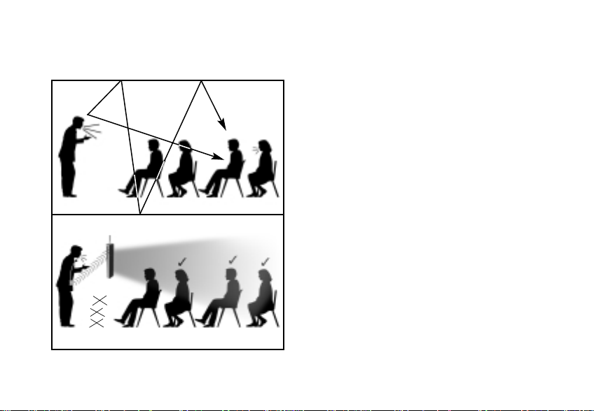
understanding sound field and its benefits
without sound field
• distance
• noise
• echo
• distance
• noise
• echo
?
?
cough!
with sound field
2
Page 5
setup tips
IMPORTANT!
Be sure you place your Radium speaker and transmitter units on their charger overnight –
for a minimum of 12 hours – before turning the power on and/or using them for the first
time. Failing to do so can reduce battery capacity.
Basic setup tips
First – Identify a front corner of the room – the location from where the teacher
normally teaches.
Second – Take a good look around, paying close
attention to power outlet and other electronic
equipment locations. Ideally, the speaker should
be placed at a 5-foot distance from other electronic equipment, such as computers or radios.
Third – Determine whether to mount the
speaker on the wall as shown in diagram 1, or
place it on a sturdy surface using the T-bar table
3
diagram 1
Page 6
setup tips (cont’d)
mount stand in diagram 2. In either case,
diagram 2
the speaker should be placed at a height of
3 feet/1 meter from the floor, or at level
closest to the listener‘s ears.
Fourth – Consider whether other Radium,
EasyListener 2, or other radio-based active
learning systems are in use in the building,
and set transmitter and receiver channels
accordingly. Every transmitter in a building
should be on its own channel. See
diagrams in section 12 for guidance.
If placing the speaker on a table or surface top, consider the following:
• Choose a location that provides easy access for the teacher, and is out of
the way of students and main traffic areas. The speaker should be placed at
least 6 feet/1.8 meters away from where the teacher stands.
4
Page 7

setup tips (cont’d)
• Choose a table or surface top that is sturdy.
Make sure the table or cabinet is structurally solid, sturdy and out of the way of foot traffic.
• Properly mount and securely fasten the T-bar speaker stand onto the bottom
of the speaker. Make sure the stand is screwed on tightly, and that the speaker does
not wobble when in an upright position.
If mounting on the wall, consider the following:
• The power supply cord needs to reach the wall outlet. Make sure the power
supply is within reach of the speaker from its wall-mounted position.
• The teacher should be able to reach the controls located on top of the speaker
once it’s mounted. Once the volume is set at a comfortable level, the speaker power
switch located on the lower right side of the speaker can be easily accessed by the
teacher. Follow the instructions on page 28 for setting the volume at the proper level.
• Never mount the speaker upside down, or horizontally. The speaker unit must be
mounted such that the controls are located at the top of the unit.
5
Page 8

daily operating tips
In the morning –
• Turn transmitter power ’on’ and put microphone on.
• Turn speaker column power ’on’. The speaker should remain plugged into a wall
power outlet during the day – with the power in the ‘on’ position. Turn power switch
to the ‘off’ position at night after each use. The internal battery is not being used while
the speaker is plugged into a wall outlet.
• To operate using the internal battery as a portable system, simply unplug the
speaker before use and plug back in after use – making sure you return power switch
to ‘off’ position while plugged-in and charging. The battery takes 6 hours to reach a full
charge; at full charge, the speaker column battery will last up to 8 hours unplugged.
In the evening after each use –
• Turn transmitter power ’off ’, and place it back onto the charg ing stand; confirm
that the ‘charge’ indicator light illuminates. Transmitters not in use should always be
placed on the charging stand – this is their home base station.
• Turn speaker column power ’off ’. Leave speaker plugged into wall power outlet,
but confirm that the power has been turned ‘off.’
6
Page 9

daily operating tips (cont’d)
Battery care and maintenance tips –
• The speaker battery will last approximately 2 years depending on usage.
• When not in use, leave speaker plugged into wall outlet with power switch in
‘off’ position.
• Keep speaker away from heating units – use/store in a cool dry place.
• When using speaker battery power (unplugged from wall), always remember to return
power switch to ‘off’ position after use.
• Never mount/use speaker horizontally or upside down. Controls should be accessible
from top of unit.
• Plan on buying new NiMH batteries for your transmitter every 12 months. Alkaline
batteries can also be used as back-ups, however, the 923C charger will not recharge
alkaline batteries. Never attempt to recharge alkaline batteries – this will cause damage
to the unit and void the product warranty.
• Remember to charge all batteries overnight before initial use.
7
Page 10

daily operating tips (cont’d)
Do not coil the microphone – since it also acts as your antenna, coiling or wrapping the
cord will affect its range and may also reduce its life.
Speak at a normal level – the system is projecting your voice for you.
8
Page 11
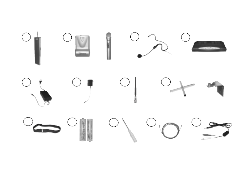
parts and accessories included with system
1
2
3
4
and/
or
5
6
7
8
or
9
9
10
11
12
13
Page 12

1 column speaker receiver
(920SR)
2 body-worn transmitter
(921T)
and/or
handheld transmitter
(922T)
3 plug-in mic for body-worn transmitter
(AT0655 shown)
4 charg ing stand
(923C)
5 power supply, receiver
(040-7402-106)
6 power supply, charging stand
(AT0819)
7 receiver antenna
(AT0831)
8 speaker table stand
(AT0823)
or
wall mounting bracket (set of 2)
(AT0820)
9 elastic belt
(AT0712)
10 AA rechargeable NiMH batteries
(AT0807)
11 channel changer screwdriver
(330-3000-101)
12 auxiliary input/output cable
(AT0532-05)
13 auxiliary input cable (3.5mm– dual RCA)
(300-6332-107)
10
Page 13
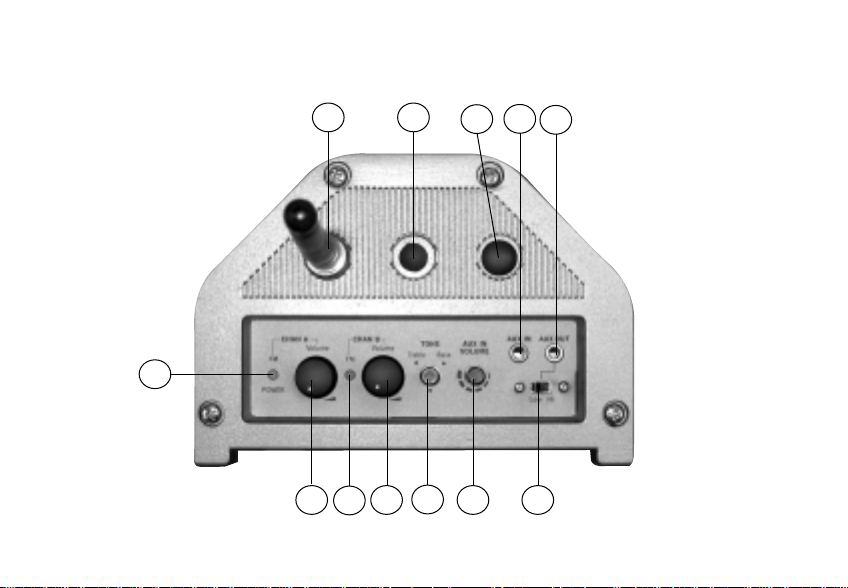
920SR column speaker features (top)
11
8 9
1
2 4 6 7
3
5
10
11
12
Page 14

1 power, low battery, and
reception status indicator
for channel A
2 power switch and volume
control for channel A
7 aux output level switch
See page 42 for level setting chart
8 antenna
9 wall mount hole
3 reception status indicator for
channel B
4 power switch and volume
control for channel B
5 tone control
6 aux input volume control
10 extra antenna hole (not used)
11 aux input jack (3.5mm, mono)
12 aux output jack (3.5mm, mono)
12
Page 15
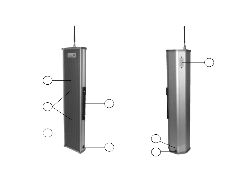
920SR column speaker features (front and back)
13
20
13
14
15
16
18
17
19
Page 16

13 speaker grille
19 power jack
14 two built-in speakers
15 internal rechargeable battery
(non-user removable)
16 handle
17 main power on/off switch
18 power and charging indicator
20 channel selectors
14
Page 17
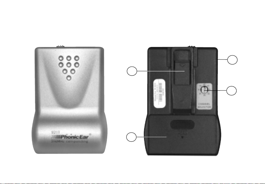
921T body-worn transmitter features
15
front
back
3
1
4
2
Page 18
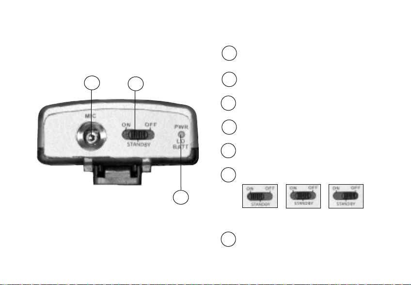
921T body-worn transmitter features (cont’d)
top
5
6
1 belt clip
2 battery compartment
3 volume control
4 channel selector
5 microphone input (2.5mm)
6 3 position power switch
7
on
standby
(mute)
off
7 power and low battery indicator light
16
Page 19
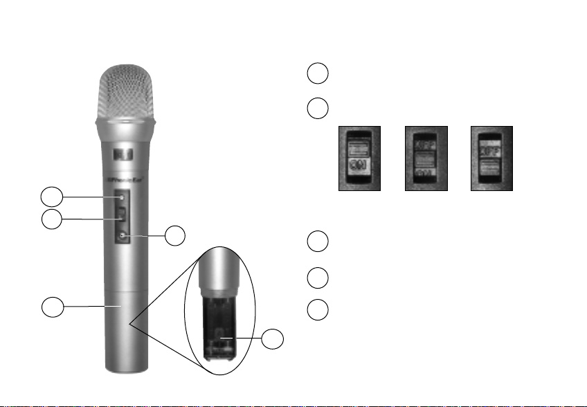
922T handheld microphone features
1 LED indicator light
2 3 position power switch
1
2
3
on
(mute)
3 channel selector
offstandby
4 battery compartment
4
5 channel selector key
(inside battery compartment)
5
17
Page 20
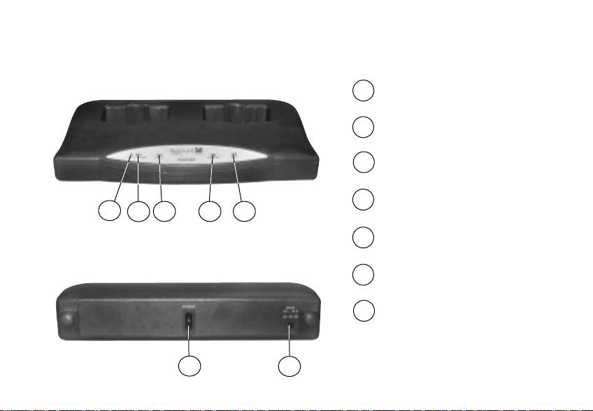
923C charging stand features
front
1 power indicator
2 pocket 1 charg ing indicator
3 pocket 1 full charge indicator
1
3 4 5
2
4 pocket 2 charg ing indicator
5 pocket 2 full charge indicator
back
6 power switch
7 DC power socket
6
7
18
Page 21
19
1
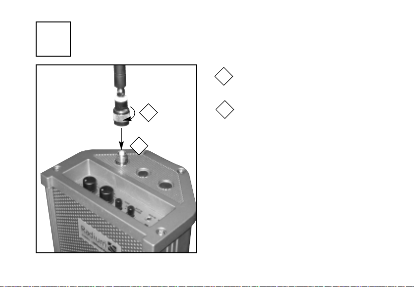
system setup and operation
attach antenna
Attach antenna to top of speaker
1
2
1
2
Turn metal base of antenna clockwise until secured tightly (do not
over-tighten)
Page 22

2
NOTE:Light is not illuminated
during normal battery operation
turn on main power
3
if using wall outlet
Plug power supply into
1
2
1
power/charging socket
Plug power supply into
2
wall socket
Turn speaker on
3
if using already charged battery
Turn speaker on
3
NOTE: Battery operating time is 5-8 hours.
20
Page 23

3
charge battery
2
1
Red light=charging
Flashing red/green (equal duration)= 80-90% charged
Long flash green, short flash red= fully charged
NOTE:Light is not illuminated during normal battery operation
21
charge nightly after every use
Plug power supply into
1
power/charging socket
Plug power supply into wall socket
2
Recharging time is 8 hours if the battery is
completely discharged and 4 to 7 hours if
battery is only partially discharged.
NOTE: Battery operating time is 5-8 hours.
Page 24

4
insert batteries in body-worn transmitter
Switch power off
1
1
Remove battery cover
2
(push and slide off)
3
_
+
2
+
_
Insert two AA rechargeable
3
NiMH batteries
WARNING: Never recharge alkaline
batteries! This will cause damage to the
unit and will void the product warranty.
22
Page 25

5
insert batteries in handheld microphone
Switch power off
1
AA Rechargeable
NiMH batteries
+
_
_
+
23
Remove battery cover
1
3
2
2
(turn counter-clockwise)
Insert two AA rechargeable
3
NiMH batteries
WARNING: Never recharge alkaline
batteries! This will cause damage to the
unit and will void the product warranty.
Page 26

6
charge transmitter(s)
Never attempt to recharge alkaline batteries! This will cause damage to
the unit and will void the product warranty.
charger back
charger front
4
Plug power supply into power jack
1
3
2
1
4
5
on back of charger stand
Plug power supply (AT0819) into
2
wall socket
Turn charger on
3
Turn transmitters off while charging
4
When green charge ready indicator
5
lights, the transmitter batteries are
full charged and ready to go. (4 to 5
hours)
24
Page 27

25
7
wait until green charge indicators light (4-5 hours)
PWR:
1
Red light = charger is turned on
CHARGING:
2
Amber light = units are being charged
READY:
3
Green light = units are fully charged
ERROR:
4
Blinking Amber light = charging
error. Improper batteries have been
detected. Check your batteries and
2
1
3
4
replace as required. Only NiMH AA
batteries can be charged. Unit will
not charge disposable Alkaline batteries or NiCad batteries.
Page 28

8
select channel
1
921T
match
match
922T
Use a screwdriver to adjust the
1
Channel A selector on the back of
the speaker to match the channel
number of either the 921T and/or
the 922T transmitter(s).
NOTE: Consider whether other Radium,
EasyListener 2, or other radio-based
active learning systems are in use in
the building, and set transmitter and
receiver channels accordingly. Every
transmitter in a building should be on
its own channel. See diagrams in section
12 for guidance.
26
Page 29

27
9
activate receivers
3
2
1
Turn receiver on by turning Channel A
1
and/or Channel B volume control
knob(s) to the right
Check power indicator light
2
(remember that main power must
also be on – see
Flash red once = adequate power
Continuous red =low battery
No light = battery does not have
power and requires recharging or
power supply is not connected properly
Turn on a 921T or 922T transmitter
3
and check FM indicator light(s):
Green= receiving FM signal
2 ):
Page 30

10
setting FM volume
Follow steps or below to adjust FM
volume
needed to set the volume level. It is difficult to
hear your own voice and make adjustments to it.
NOTE: The average volume setting is in the
11:00 position (see photo), but may change
depending on room acoustics and noise level.
With a sound level meter - Take a level reading in the “A” setting in the center of the
1
room during normal classroom activity, and another reading of the teacher's amplified voice
(without the class activity). The level of the teacher's voice should be set between 10-15
decibels above room noise level.
Without a sound level meter - First, ask someone other than yourself (if you are the
2
teacher) to listen to the amplified voice and make volume adjustments. An ideal volume level
is achieved when the listener can hear the amplified voice at a comfortable level and the volume level from the speaker and teacher’s mouth is comparable. If you can hear yourself
through the loudspeakers, the volume setting may be too high and should be decreased.
setting to proper level. Two people are
2
1
28
Page 31

11
1m/3ft
29
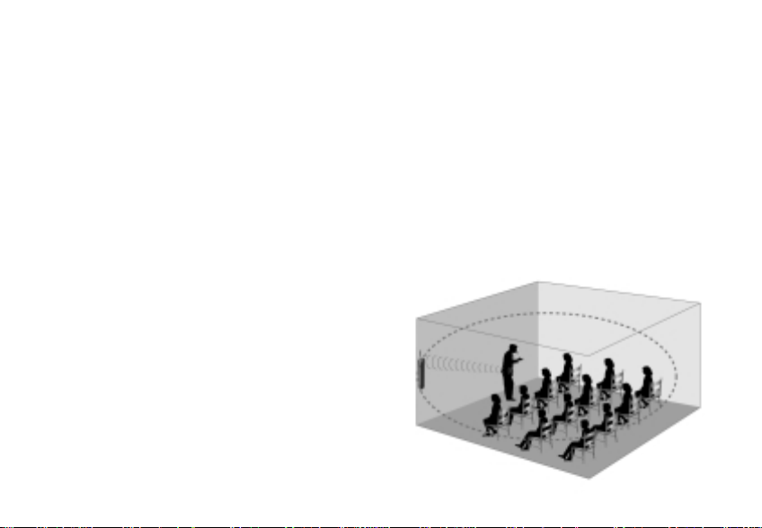
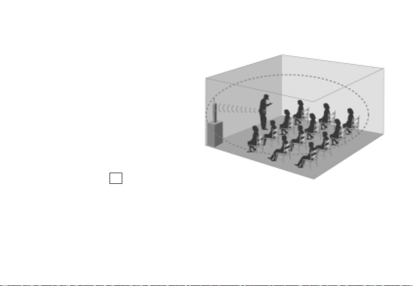
920SR speaker placement and mounting
speaker positioning
Place speaker in a corner of the room facing
listeners. Mount speaker on wall using brackets or place speaker on a surface using a
speaker stand. The bottom of the speaker
should be about 1 meter/3 feet from the floor.
(See setup tips on page 3).
Page 32

12a
channel mapping: placement diagram for multiple
system installations (double channel - 8 rooms total)
= suggested placement of
920SR speaker
Channel A: 44
Channel B: 54
Channel A: 48
Channel B: 58
Channel A: 41
Channel B: 51
hallway
Channel A: 45
Channel B: 55
Channel A: 46
Channel B: 56
Channel A: 47
Channel B: 57
Channel A: 42
Channel B: 52
Channel A: 43
Channel B: 53
30
Page 33

12b
channel mapping: placement diagram for multiple
system installations (single channel - 16 rooms total)
31
Channel: 41
Channel: 45
Channel: 51
Channel: 55
hallway
Channel: 42
Channel: 46
Channel: 52
Channel: 56
Channel: 43
Channel: 47
Channel: 53
Channel: 57
hallway
Channel: 44
Channel: 48
Channel: 54
Channel: 58
Page 34

13a
wall mounting (option 1)
Attach brackets to wall
1
2
AT0820
Screw mounting brackets to top and
2
bottom of speaker
1
32
Page 35

13b
33
mounting on floor stand (option 2)
Screw speaker stand into hole on
1
bottom of speaker.
• Turn clockwise to tighten
• Turn counter-clockwise to loosen
1
AT0823
AT0824 floor stand
is also available
Page 36

13c
seal wall mounting hole if using table stand
Place plastic plug into mounting
1
bracket hole on top of speaker to
keep out dust
1
34
Page 37

14
35
921T body-worn transmitter operation
plug microphone in
Plug microphone cord into
Boom mic cord
1
1
mic jack on top of body-worn
transmitter
Page 38

15
put on microphone and adjust for proper distance
from mouth
Maximum distance from mic to mouth is 6 in/(15cm); 3 in/(7.5cm) is ideal.
optimum
AT0655 boom mic (two wearing options)
performance:
7.5cm/3in
AT0816 collar mic
performance: ★★★
optional
★★★★
AT0814 earhook mic
performance: ★★★★
15cm/
6in max.
AT0291-L directional lapel mic
performance: ★★
36
Page 39

16
turn power on
Switch power on
1
37
1
2
Check indicator light:
2
Continuous green = adequate power
Continuous red =low battery
battery life
NiMH rechargeable AA = 12 hours (approx.)
Alkaline disposable AA =15 hours (approx.)
WARNING: Never recharge alkaline
batteries! This will cause damage to the unit
and will void the product warranty.
Page 40

17
adjust transmitter(s) frequency
1
921T
2
922T
must match
must match
920SR
Use a screwdriver to turn frequency
1
selector to channel number that matches the channel set on column speaker
If using both body-worn and hand-
2
held transmitters set one transmitter
channel to match a Channel A on
the speaker column, and the other
transmitter channel to match
a Channel B channel on the
speaker column.
NOTE: Never operate two transmitters on
the same channel or interference will result.
To use two transmitters, set the first to
match receiver Channel A and the second
to match receiver Channel B.
38
Page 41

18
39
adjust body-worn transmitter volume
1
2
Increase transmitter volume for
1
greater mic sensitivity and sound
clarity
Reduce transmitter volume if feed-
2
back occurs
Page 42

19
activate standby/mute mode
1
Activate standby mode to
1
eliminate white noise when
not speaking
MUTE: Standby mode can also be used as
a microphone/transmitter mute switch.
The mute feature allows teachers to have a
private conversation without needing to
turn the transmitter off.
40
Page 43

20
41
922T handheld transmitter operation
turn power on
Turn power on by pushing power
1
switch up
1
Page 44

21
check indicator light
Check indicator light:
1
Continuous green = adequate power
Continuous red = low battery
1
battery life
NiMH rechargeable AA = 12 hours (approx.)
Alkaline disposable AA = 15 hours (approx.)
WARNING: Never recharge alkaline
batteries! This will cause damage to the unit
and will void the product warranty.
42
Page 45

22
43
remove channel adjustment key
1
2
2
1
Open battery compartment door and
remove batteries
Remove channel adjustment key
Page 46

23
adjust transmitter channel to match receiver channel
Using adjustment key, turn channel
1
frequency selector to channel number
that matches the channel set on
column speaker
atch
ust m
1
m
920SR
NOTE: Never operate two transmitters on
the same channel or interference will result.
To use two transmitters, set the first to
match receiver Channel A and the second
to match receiver Channel B.
44
Page 47

24
45
standby mode
Activate standby mode to mute
1
voice and eliminate white noise
when not speaking
1
Page 48

25
transmitters that can be used with 920SR receiver/speaker
★★★★ = most compatible ★ = least compatible
transmitter
921T ✔ ★★★★ none
Radium
922T ✔ ★★★★ none
Radium
330T ✔ ★★★★ none
EasyListener 2
300TS-216 ✔ ★★★ none
Sprite
Lexis transmitter ✔ ★★★ ✔
(as mic)
Phonak ✔ ★★★ ✔
Campus S TX5
Phonak N/A N/A N/A
HandyMic TX3
compatible performance accessory
(no adaptor
cord required)
rating needed
comments
best when used with AT0655 boom mic
a) Lexis requires the use of the AT0655R boom mic
b) may require use of external antenna for better
range (389-02-120-02)
c) set microphone to omni mode
d) set sensitivity level to HI
due to feedback, use of external boom mic from
Phonak is recommended
a) built-in mic prone to feedback
b) requires use of external mic, which the
HandyMic does not accommodate
46
Page 49

26
aux in – connecting to TV, CD, VCR, etc.
connecting speaker to TV, CD, VCR, etc.
Using either the AT0532-05 or
1
300-6332-107 adaptor cords,
1
2
connect VCR, TV, CD, computer
or other audio source to AUX IN
port on top of speaker
Use AUX IN VOLUME control to
2
adjust volume
47
AT0532-05
or
VCR
300-6332-107
NOTE: AUX IN can be used simultaneously
with both Channel A & B.
Page 50

27
AT0529A
Ant jack
2
aux out – connecting to personal FM devices
connecting to SOLARIS, EASY LISTENER, SPRITE or other transmitter
(for rebroadcast of audio to students with hearing impairment)
Connect AT0532-05(ft) cord to
1
3
AT0532-05
Aux In
1
1
AUX input jack of either SOLARIS,
EASY LISTENER
,SPRITE, or other trans-
mitter. Connect other end of cable to
AUX OUT port on top of speaker.
Connect antenna AT0529A (included
2
with transmitter system) to Mic/Ant
jack on transmitter
Refer to level setting gide on next
3
page to identify proper level for
your transmitter
PE 571T PE 300T PE 300TS
OR OR
48
Page 51

28
aux out transmitter compatibility chart and level setting guide
NOTE: Common transmitters and recommended level settings are shown below. Because the level
setting is universal, other transmitters not listed below may be used as well – simply set the aux
out
level to the position at which the receiver wearer hears a strong distortion-free signal.
product name/part aux in jack size aux out level setting
Easy Listener 300T 3.5mm High
Sprite 300TS 3.5mm High
Sprite 300TS-216 3.5mm High
Solaris 571T 3.5mm High
Lexis 871T transmitter 3.5mm High
Phonak Campus S TX5 3.5mm High
Phonak HandyMic TX3 3.5mm† High
Phonak MicroVox TX2 2.5mm* High
* For transmitters with a 3.5mm jack size, simply attach the transmitter to the AT0805 aux out accessory
cord. For 2.5mm products, use the aux out adapter plug (310-2544-1341)
† Requires special adaptor cord provided by Phonak (P/N 52117) and Radio Shack adaptor (P/N 274387).
49
Page 52

additional system accessories
microphone options
AT0655
behind-the-neck
boom microphone
AT0814
earhook microphone
receiver accessories
AT0820
wall mounting bracket
(set of 2)
AT0823
speaker table stand
AT0816
FM collar microphone
with mute switch
AT0824
speaker floor stand
AT0291-L
directional microphone
with lavalier cord
AT0822
carrying bag
AT0801
aux-box (adds four
additional audio inputs)
50
Page 53

additional system accessories (cont’d)
transmitter accessories
AT0532-15
auxiliary input/
output cable
(3.5mm–dual RCA)
(15ft/4.6m)
51
AT0529A
transmitter antenna
310-2544-1341
aux-out adaptor plug
(3.5mm– 2.5mm)
AT0807
AA rechargeable
NiMH batteries
Page 54

troubleshooting
no FM reception (Channel A, Channel
B indicator does not have green light)
• Verify the transmitter is turned on
• Verify the frequency number on the transmitter matches the frequency number
on receiver
• Verify transmitter batteries are charged
• Verify speaker antenna is connected properly
weak sound from speaker
• Increase volume on the speaker
• Turn up transmitter volume
• Make sure AT0655 boom microphone (or
other mic) is being worn correctly
speaker is receiving a signal but no
sound is coming out
• Verify microphone is connected properly to
transmitter and is working correctly
feedback from speaker
• Turn down the volume on the transmitter
• Turn down the volume on the speaker
• Make sure the person wearing the transmitter is not too close to the speaker
• Move speaker so that it is facing away from
presenter and toward listeners
• Make sure AT0655 boom microphone (or
other mic) is being worn correctly
52
Page 55

troubleshooting (cont’d)
speaker does not turn on (power
indicator does not flash red)
• Verify main power switch on the bottom of
the unit is turned on
• Verify Channel A and Channel B volume
control knobs are turned on
• Verify power supply is plugged securely into
speaker and wall socket
• Verify wall socket works
speaker battery does not charge
• Connect power supply to speaker and
charge for four hours. If speaker battery
does not hold a charge, send the unit to
Phonic Ear Service department for replacement (battery must be replaced after one
year of continuous use).
53
speaker is picking up FM interference
or hum
• Check to make sure no other wireless systems are operating on similar frequencies
• Check to make sure the system is not placed
too close to a computer
• Check to make sure metal objects are not
placed too close to transmitter or speaker
(i.e. jewelry, metal shelves)
amber charge light is flashing when I
attempt to charge my transmitter
• Replace your batteries with a set of new
NiMH cells (AT0807).
Page 56

Radium channel numbers and corresponding frequencies
Channel # Channel A Channel # Channel B
41 . . . . . . . . . . . 216.025 MHz 51 . . . . . . . . . . 216.525MHz
42 . . . . . . . . . . .216.075MHz 52 . . . . . . . . . .216.575MHz
43 . . . . . . . . . . . 216.125MHz 53 . . . . . . . . . . 216.625MHz
44 . . . . . . . . . . .216.175MHz 54 . . . . . . . . . .216.675MHz
45 . . . . . . . . . . .216.225MHz 55 . . . . . . . . . .216.725MHz
46 . . . . . . . . . . .216.275MHz 56 . . . . . . . . . .216.775MHz
47 . . . . . . . . . . . 216.325MHz 57 . . . . . . . . . . 216.825MHz
48 . . . . . . . . . . .216.375MHz 58 . . . . . . . . . .216.875MHz
54
Page 57

product specifications
two channel column speaker: 920SR
carrier frequency range/ 216.025–216.875MHz
frequencies 16 total
modulation FM (F3E)
output power maximum 36W @ 4Ω x2
power requirements 110V/240V AC adaptor 15V DC/2A,
Battery 12V/2.7A
(rechargeable, sealed lead-acid,
1- 1.5 year life with continuous usage)
frequency response 100Hz –9kHz
total harmonic distortion <2%
system signal-to-noise >65 dB (at rated output)
ratio
inputs AUX x 1, power & charge
output AUX x 1 (High: 700 mV/Low: 100mV)
controls tone, channel A & channel B
power/volume, aux volume,
high/low output, master power,
channel selector
55
dimensions (WxHxD) 100 x 660 x 145 mm/ 3.9 x 26 x 5.7 in
weight 5kg/11lbs
recharging time 8 hours for initial charging
4– 7 hours for recharging
battery operating time 5–8 hours (continuous operation)
speaker stand optional table stand (AT0823),
floor stand (AT0824), or
wall brackets (AT0820)
de-emphasis 75µs
squelch RSSI
Page 58

product specifications (cont’d)
body-worn transmitter: 921T
carrier frequency range/ 216.025 –216.875MHz
frequencies 16 total
modulation FM (F3E)
total harmonic distortion <1.5%
frequency response 50Hz to 12KHz
frequency stability .0005%
maximum modulation ± 25KHz, with level limiting
pre-emphasis 75µs
dynamic range 100dB
operating range >34m/110ft
dimensions (WxHx
inputs/outputs 2.5mm microphone input jack
D
) 65 x 90 x 25 mm/ 2.5 x 3.5 x 1 in
weight 51g/1.8oz
controls on/standby/off/channel selector/volume
battery NiMH rechargeable (1600mA);
alkaline disposable (2AA)
battery life NiMH rechargeable: 12 hours (approx.)
alkaline disposable: 15 hours (approx.)
recharging time 6 hours
56
Page 59

product specifications (cont’d)
handheld mic transmitter: 922T
carrier frequency range/ 216.025–216.875MHz
frequencies 16 total (see chart below)
mic dynamic microphone
antenna built-in
RF output 15mW
battery NiMH rechargeable battery;
alkaline disposable; 1.5V x 2 AA
battery life NiMH rechargeable: 12 hours (approx.)
alkaline disposable: 15 hours (approx.)
recharging time 6 hours (NiMH batteries)
dimensions (dia x length) 54 x 237 mm/2.1 x 9.3 in
weight 230g/8.1oz
controls on/standby/off/channel selector
57
charging stand: 923C
power supply AC adaptor (DC 12V/0.5A)
indicator lights LED green = battery ready
recharging time NiMH (1300mA): 4 hr
dimensions (Wx
controls on/off switch
LED orange = recharging
LED red = power on
LED blinking orange = fault (battery bad)
xD) 135 x 47 x 230 mm/5.3 x 1.9 x 9 in
H
weight 360g/12.7oz
Page 60

warranty
time period of warranty
This warranty will go into effect upon the date
of purchase and will stay in effect as long as
the instrument remains the property of the original owner. E
O
NWAVE
ASYLISTENER 2
™
have a 3-year warranty. All other prod-
™
,VOCAL
IGHT
™
and
ucts have a 1 year warranty.
what is covered by this warranty
Any electronic component, which because of workmanship, manufacturing or design defects, fails to
function properly under normal use during the life of
this warranty will be replaced or repaired at no charge
for parts or labor, when returned to the factory
service center. Transportation in is paid by the customer. If it is determined that repair is not
feasible, the entire unit may be replaced with an equivalent unit upon mutual agreement of the
manufacturer and customer.
what is not covered by this warranty
This limited warranty does not apply to:
1. Malfunctions resulting from abuse, neglect
or accident
2.
I
nstruments connected, installed, used or adjusted
in any manner contrary to instructions provided
by the manufacturer
3. Consequential damages and damages resulting
from delay or loss of this instrument. The exclusive remedy under this warranty is strictly limited
to repair or replacement as herein provided
4. Products damaged in transit unless investigated
by the shipper and returned to the warrantor
with the investigation report
5. Peripheral accessories as itemized within the
product specification sheet as applicable, when
such items are not returned within 1 year from
original purchase
6. Batteries if applicable
58
Page 61

warranty (cont’d)
Phonic Ear Inc. reserves the right to make changes in
the design or construction of any of its instruments at
any time without incurring any obligation to make any
changes whatsoever on units previously purchased.
This warranty is in lieu of all other expressed warranties.
All expressed and implied warranties will terminate upon
the expiration of this written warranty . No repr esentative
or person is authorized to represent or assume for us any
liability in connection with the sale or use of our products other than as set forth above.
what to do if you have questions
If you have any questions about service, call the service
department at
59
800.227.0735, then press 7.
what to do if you need service
If you require service under the warranty terms, obtain a
service order form either online at
com/support.asp
service department at
or through our U.S. customer
800.227.0735, then press 5
www.phonicear .
(or +1.707.769.1110 outside the U.S.). Fill the form
out completely remembering to include:
1. Description of the problem
2. Your billing address
3. Your shipping address (if different from
billing address)
4. Contact name and phone number
5. A P.O. number if the equipment is not under a
warranty or service contract
Page 62

warranty (cont’d)
Then, carefully package the equipment in the
original shipping container
to prevent damage
and send it postpaid to the service center near you:
USA/International:
Phonic Ear Inc.
3880 Cypress Drive
Petaluma, CA 94954-7600
U.S.A.
In Canada:
Phonic Ear Ltd.
10-7475 Kimbel Street
Mississauga, Ontario
L5S 1E7 Canada
what to do if you have questions
If you have any questions about service, call the service
department at
800.227.0735, then press 7.
about your batteries
To ensure that your batteries are as fresh as possible
upon arrival, we have intentionally not installed
them in your equipment.
install your batteries in your equipment now,
then charge overnight before initial use
(see user guide for charging procedure).
avoid battery corrosion
To avoid battery corrosion and damage to your
equipment,
rechargeable alkaline batteries.
do not recharge disposable or
Before charging any Phonic Ear equipment make sure only
NiMH rechargeable batteries are installed. As an
added precaution, remove batteries if the equipment
will not be used for several weeks.
60
Page 63

regulatory approvals and clearances
transmitter
This transmitter is authorized by rule under the Low
Power Radio Service (47 C.F.R. Part 95) and must
not cause harmful interference to TV reception or
United States Navy SPASUR installations. You do
not need an FCC license to operate this transmitter.
This transmitter may only be used to provide: auditory assistance to persons with disabilities, persons
who require language translation, or persons in educational settings; health care services to the ill; law
enforcement tracking services under agreement with
a law enforcement agency; or automated maritime
telecommunications system (AMTS) network control
communications. Two-way voice communications
and all other types of uses not mentioned above are
expressly prohibited.
This device may not interfere with TV reception or
federal government radar, and must accept any interference received, including interference that may
cause undesired operation.
61
IM PO RTANT NOTE: To comply with FCC RF
exposure compliance requirements, only use supplied antenna that is sold with this transmitter.
Use of any other antenna which has not been
approved by the manufacturer will violate FCC
rules and regulation and void the user’s authority
to operate this device. This device and its antenna(s)
must not be co-located or operating in conjunction
with any other antenna or transmitter.
Page 64

regulatory approvals and clearances (cont’d)
receiver: part 15, subpart B
Radium Receiver/Speaker 920SR
Tested to comply with
FCC Standards
FOR HOME OR OFFICE U SE
This equipment has been tested and found to
comply with the limits for a Class B digital
device, pursuant to Part 15 of the FCC Rules.
These limits are designed to provide reasonable
protection against harmful interference in a residential installation. This equipment generates,
uses and can radiate radio frequency energy and,
if not installed and used in accordance with the
instructions, may cause harmful interference to
radio communications. However, there is no guarantee that interference will not occur in a particular installation. If this equipment does cause
harmful interference to radio or television reception, which can be determined by turning the
equipment off and on, the user is encouraged to
try to correct the interference by one or more of
the following measures:
• Reorient or relocate the receiving antenna.
• Increase the separation between the equipment
and receiver.
• Connect the equipment into an outlet on a
circuit different from that to which the receiver
is connected.
• Consult the dealer or an experienced radio/TV
technician for help.
62
Page 65

regulatory approvals and clearances (cont’d)
FCC notes
The Radium sound field system is approved by
the FCC (Federal Communications Commission).
The use of the system may be governed by specific
FCC rules and FCC licensing or notifications may
be required. Consult your local FCC office for
detailed information.
Phonic Ear FM receivers and FM transmitters,
when required, are approved by the Federal
Communications Commission (FCC) in the U.S.
and Industry Canada. Other government
approvals are available upon request. (Other international regulations may also apply.)
Any changes or modifications made to any government-approved element of this instrument,
without the express approval of Phonic Ear Inc in
writing, could void the user's authority to operate
those elements of the system.
63
Par t 95
This transmitter is authorized by rule under the
Low Power Radio Service (47 CFR Part 95) and
must not cause harmful interference to TV reception or United States Navy SPASUR installations. You do not need an FCC license to operate this transmitter. This transmitter may only be
used to provide auditory assistance to persons
with disabilities, persons who require language
translation, or persons in educational settings;
health care services to the ill; law enforcement
tracking service under agreement with a law
enforcement agency; or automated maritime
telecommunication system (AMTS) network
control communications. Two-way voice communications and all other types of uses not mentioned above are expressly prohibited.
Page 66

regulatory approvals and clearances (cont’d)
This device may not cause interference and must
accept any interference received, including interference that may cause undesired operation.
These devices may not interfere with TV reception or Federal Government radar.
IC notes
This Class B digital apparatus complies with
Canadian ICES-003.
Cet appareil numérique de la classe B est
conforme à la norme NMB-003 du Canada.
The term "IC:" before the radio certification
number only signifies that Industry of Canada
technical specifications were met.
If TV channel 13 is used in the area, the installer
shall reduce or adjust the RF radiated power so
that near-by TV channel 13 receivers do not
receive radio interference from the system
installed. Suggestions: A test with a TV receiver
equipped with "rabbit-ear antenna" and tuned to
channel 13 should be conducted, at the perimeter
of the users' intended coverage area and not
over-lapping other user's areas without the latter's
consent. If this does not solve the problem, a
channel near the 217 MHz edge and not near
216 MHz should be tried.
This product has been cleared
by the U.S. Food and Drug
Administration for use by persons with normal
hearing and hearing impairment.
64
Page 67

u.s.a. 800.227.0735, then press 5•canada 800.263.8700 • international +45 3917 7101
© 2005 Phonic Ear Inc. Phonic Ear and the names of Phonic Ear products are trademarks or registered trademarks of Phonic Ear Inc. in the U.S. and
other countries. Product specifications and accessories subject to change without notice. 821-7403-101/Rev. D/4724 0205
 Loading...