

Page 1

B/W 9-Inch 4-Channel
Security Monitor
Owner’s Manual
Please read before using this equipment.
Page 2
ˆ
Introduction
Your RadioShack B/W 9-Inch 4-Channel Security Monitor is a n i mp orta nt add iti on to y ou r
existing security system. It features flexible
operation with many security-oriented benefits. Your monitor includes these features.
9-Inch (measured diagonally) Monitor —
provides a clear view for security detail.
800-Line Resolution
picture clarity.
Operates Up to Four Cameras
rately) — for maximum security coverage.
Standard TV Controls
sound and picture settings.
Provided Connector Cables —
quickly make connections to cameras, VCRs
and standard TVs.
Automatic View Sequencing of Al l Came r as
— lets you check each camera’s scene
quickly and automatically.
Adjustable Sequenced Viewing Time for
All Connected Cameras
specific view times for special requirements.
Adjustable Sequence Order
designate the order in which you view multiple camera installations.
— provides superior
(sold sepa-
— let you adjust
let you
— lets you set
— lets you
Warning:
reduce the risk of electrical shock or damage, do not expose this system to rain or
moisture.
WARNING:
shock hazard, do not expose this product to rain
or moisture.
This system is not waterproof. To
To reduce the risk of fire or
CAUTION
RISK OF ELECTRIC SHOCK.
DO NOT OPEN.
CAUTION:
ELECTRIC SHOCK, DO NOT REMOVE
COVER OR BACK. NO USER-SERVICEABLE PARTS INSIDE. REFER SERVICING
TO QUALIFIED PERSONNEL.
!
TO REDUCE THE RISK OF
This symbol is intended to alert
you to the presence of uninsulated dangerous voltage within
the product’s enclosure that might
be of sufficient magnitude to constitute a risk of electric shock. Do
not open the product’s case.
This symbol is intended to inform
you that important operating and
maintenance instructions are
included in the literature accompanying this product.
!
Instant Camera Selection
any camera at the press of a button.
VCR Connections
and record and play back all camera operations.
Two-Way Audio
nication bet ween a camera lo cation and the
monitor.
2
— let you connect a VCR
— provides audio commu-
RadioShack and RadioShack.com are trademarks used by RadioShack Corporation.
— lets you check
©
1999, 2000 RadioShack Corporation.
All Rights Reserved.
Introduction
The graphical symbols with supplemental markings are located on the back of the monitor.
INSTALLATION GUIDELINES
Before you install the monitor and any cameras, carefully plan the location for each and
plan where you will route the connection cables. Keep in mind the following when planning the installation.
Page 3
• This system is designed for indoor use
only.
• Do not install any camera or monitor
where it will be exposed to high humidity
or rain.
• Select a location for the monitor that will
not be blocked by objects or traffic.
Make sure the selected location is not in
direct sunlight or in line-of-sight with a
direct light source that might make
observing the monitor difficult.
• Do not route any of the connecting
cables close to power or telephone
lines, transformers, or other electrical
equipment that could interfere with your
security syst em or with any nearby systems or devices.
• Select a location for the camera and
monitor so the ambient temperature is
between 14° — 113°F (–10° — 45°C).
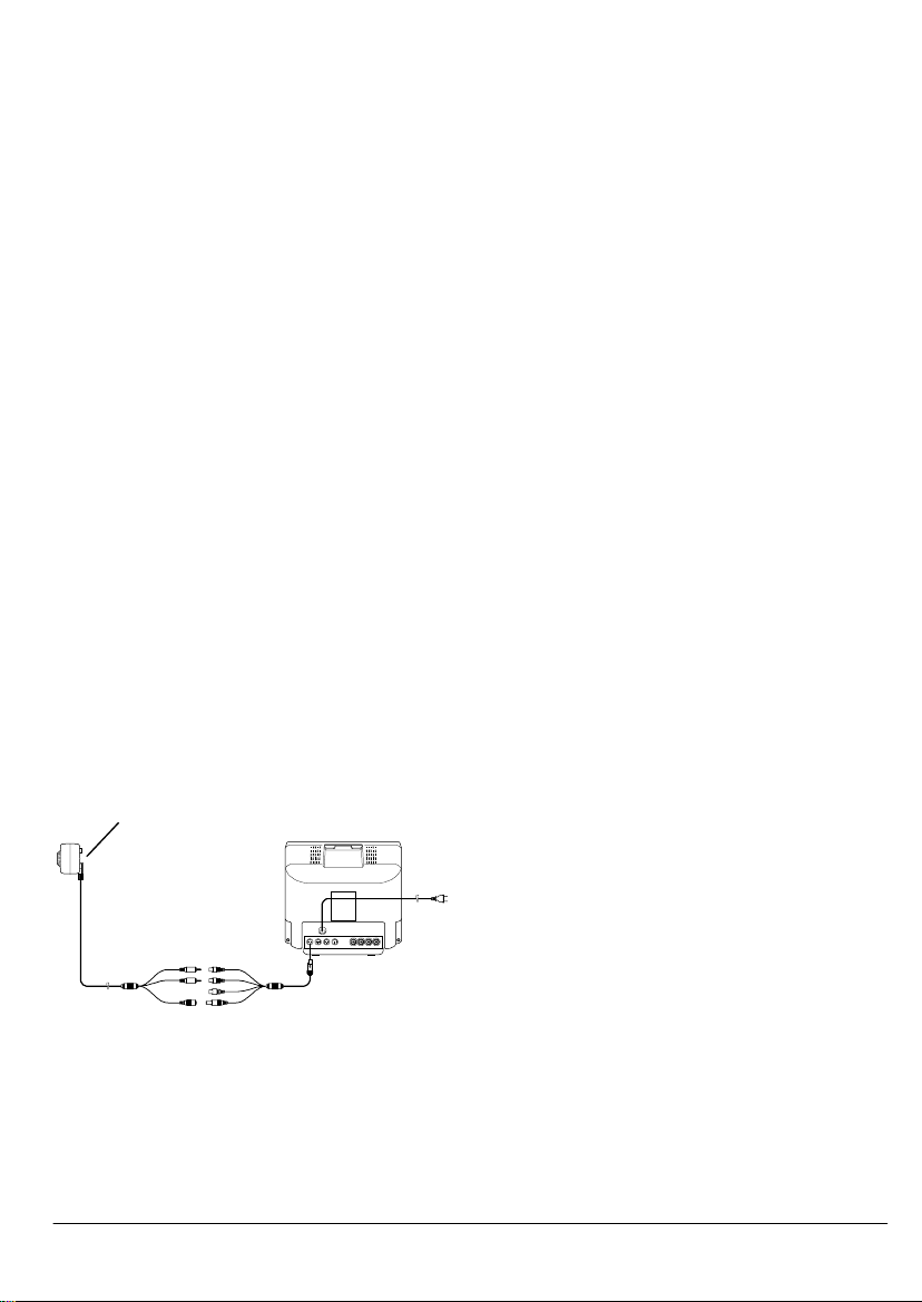
CONNECTING A CAMERA
The monitor comes with two cables that let
you connect one or two cameras to the monitor. Additional cables for more cameras are
available at your local RadioShack store.
Follow these steps to connect either the RadioShack Cat. No. 49-2512 or 49-2513 model cameras.
Camera
Cat. No. 49-2512
1. Connect the mini-DIN plug at one end of
the supplied 2-foot cable to one of the
four mini-DIN jacks (
CA1
rear of the monitor.
2. The other end of the cable has three
jacks and one barrel plug: a white
to
CA4
) on the
AUDIO (IN), a yellow VIDEO (IN), a
black AUDIO (OUT) and a DC 12V
(OUT) barrel plug. Connect the yellow
jack, the white jack, and the barrel plug
to the long cable that comes with your
camera as follows:
• Connect the yellow AUDIO (IN) jack
to the yellow AUDIO plug.
• Connect the white VIDEO (IN) jack to
the white VIDEO plug.
• For the Cat. No. 49-2512 camera
only, connect the DC 12V (OUT) barrel plug to the DC12V 200mA barrel
receptacle on the long cable. The
CA
jacks on the monitor, rather than the
external adapter supplied with the
camera, provide the operating power
to the camera.
• For the Cat. No. 49-2513 camera
only, connect the black AUDIO (OUT)
jack to the the camera’s red audio
input plug.
Warnings:
• Do not connect the Cat. No. 49-2513
camera to the DC 12V (OUT) plug.
Doing so can damage the monitor or
camera. Use only the AC adapter
supplied with the camera.
• To use this m onitor to power cameras
other th an Cat. No. 49- 2512, be sure
the selected camera requires 12V DC
at no more than 200mA and has a
matching connector tha t fits the barrel
plug of the monitor’s provided cable
with the TIP +. If you are not sure, do
not attempt to connect that camera.
Instead, use the power supply provided with the camera.
3. Connect the mini-DIN plug on the end of
1
the 79
/2-foot cable (supplied with Cat.
No. 49-2512) into the mini-DIN jack on
the back o f the Cat. No. 4 9-2512 camera, or the distribution box of Cat. No.
49-2513.
4. Plug th e mon it or ’s A C pow er co rd i nto a
standard AC outlet.
Introduction
3
Page 4

ˆ
Operation
POWER
Press
dicator lights and the monitor automatically
scans the input to all of its jacks in sequence.
If you did not connect a camera to one or
more of the jacks, the monitor displays a
blank screen when it scans those jacks. To
have the monitor skip a blank screen, see
“Programming a Viewing Sequence.”
To manually select a single camera’s view,
AUTO.
press
Then press the camera button of the camera
you want to observe (
CA4
).
on the monitor. The AUTO in-
The AUTO indicator turns off.
CA1, CA2, CA3
, or
Note
: When you turn off th e m on ito r’s po wer,
the view time resets to 5 seconds for each
camera.
Programming a Viewing
Sequence
The monitor scans cameras 1 through 4 in
that order each time you turn on the system.
To set a different scan order, with the AUTO
indicator on, press
CA4
in the desired order. To skip any cam-
era, do not press that camera's button.
For example, to view cameras 3, 2, and 1,
and skip camera 4, press
CA1
. (Do not press
To reset the viewing sequence, press
AUTO
then
all four cameras in order (1–4).
Note:
change the view time settings.
. The system re sumes scanning
Pressing
CA1, CA2, CA3,
CA3, CA2
CA4
.)
VCR
then
AUTO
and
, then
VCR
does not
Adjusting the Picture/Sound
Controls
Setting the Camera View Time
When you turn on the monitor, it is preset to
scan all the camera connections, pausing 5
seconds at each.
To change the view time for all the connected cameras , hold do wn
button for the amount of time you want them
to scan (during each cycle). For example, to
set the view time to 10 seconds, hold down
AUTO
both buttons. You can set a view time of up
to 60 seconds.
4
and
CA4
for 10 seconds then rele ase
AUTO
and the
CA4
Operation
The monitor has picture and sound controls
similar to a standard TV. To access the controls, press
er.
PUSH
on the front panel flip cov-
Page 5

CONT
(Contrast) — Adjusts the contrast be-
tween the dark and light parts of the picture.
BRT
(Brightness) — Adjusts the overall
brightness of the screen.
jacks of your VCR using video-quality shielded cables (not supplied).
Monitor
V-HOLD
from rolling.
H-HOLD
tal tearing.
AUDIO
ume picked up by all camera microphones.
(Vertical H old) — St ops the picture
(Horizontal Hold) — Stops horizon-
(Volume) — Adjusts the sound vol-
Using the Monitor Microphone
If you use the monitor with a camera capable
of 2-way audio communications, follow these
steps to speak to someone near the camera.
1. Hold down
lights. Speak into the
beneath the screen in the lower right
corner.
Note:
scanning of each connected camera.
2. When you finish speaking, press
to resume scanning all cameras, if
desired.
TALK.
Pressing
The TALK indicator
MIC
located
TALK
interrupts the
AUTO
Using a VCR
To record the audio and video input from
each camera, you can connect a VCR
equipped with separate audio and video input jacks to the monitor . You can then play
back the recording on the monitor or on a
standard TV equipped with AV input jacks.
To record the sound and picture from your
cameras, connect the monitor’s
A OUT
jacks to the audio and video input
V OUT
and
VCR
If you plan to play the recorded tape through
the monitor, connect the monitor’s
A IN
jacks to the VCR’s audio and video output jacks using a v ideo-qu ality shiel ded c able
(not supplied).
V IN
and
VCR Recording
Follow these steps to record the input from
one or more cameras.
1. Turn on the system and the VCR.
2. Load a blank video cassette, or one you
want to record over, into the VCR.
3. Most VCRs have either a separate
switch or built-in ele ctr oni c p r ogra mm in g
to let you switch between a TV source
as input and another source connected
to the audio/video jacks. Using the
method appropriate for you r VCR , se lec t
the source connected to the audio/video
input jacks.
Note:
If your VCR has no provision for
recording a separate external source,
special accessories are available at your
local RadioShack store.
4. Selec t the desired record ing speed and
other settings on your VCR.
5. Begin recording.
Operation
5
Page 6

VCR Playback to the Monitor
To view a recorded ta pe thro ugh th e m on itor ,
follow these steps.
1. Turn on the monitor and the VCR.
2. Press
ˆ
VCR
on the monitor's front panel.
The VCR indicator lights.
Care
3. Begin playback on the VCR.
4. When you finish playing the recorded
tape and have turned off the VCR, press
AUTO
to return to sequential camera
scanning
Keep the monitor dry; if it gets wet, wipe it
dry immediately. Use and store the monitor
only in normal temperature environments.
Handle the monitor carefully; do not drop it.
Keep the monitor away from dust and dirt,
and wipe it with a damp cloth occasionally to
keep it looking new.
Modifying o r tamperi ng wi th the mo nitor’ s internal com ponents can ca use a malfuncti on
and might invalidate its warranty and void
your FCC authorization to operate it. If your
monitor is not performing as it should, take it
to your local RadioShack store for assistance.
TROUBLESHOOTING
If your monitor is not working as it should,
these suggestions might help you eliminate
the problem. If the monitor still does not operate properly, take it to your local RadioShack store for assistance.
No picture appears
• Be sure the monitor's power is on.
• Check the connections between the
camera and the monitor. Be sure audio
and video cable connections are not
reversed and that power connections
are secure. Try all the CA jacks on the
rear apron of your monitor.
•Adjust
CONT
.
.
Image is not clear
•Adjust
•Adjust
•Adjust
• Be sure the selected camera is not
Cannot record to a VCR.
• Check the cable connections. Be sure
• Be sure the VCR is set to audio/video
• Check the connections between the
Cannot play back using the monitor
• Check the cable connections. Be sure
• Be sure the VCR is set to play.
CONT
BRT
V-HOLD
pointed directly at a light source.
audio and video cables are not
reversed.
input and is set to record.
camera and the monitor.
the audio and video cables are not
reversed.
.
.
.
H-HOLD
or
.
.
6
Care
Page 7

ˆ
Specifications
Picture Tube ............................................................................B/W 10" tube with 90° deflection
Power Source ................................................................................................... AC 120V, 60 Hz
Power Consumption ................................................................................................. Max. 40 W
Resolution .................................................................................... More than 800 lines at center
TV System ............................................................................................................. EIA standard
Camera Scan Time .............................................................................................. 1–60 seconds
Video-in ....................................................................................... 1 V p-p composite at 75 ohm;
4 DIN from camera, 1 phono from VCR
Audio-in ....................................................................... 4 DIN from camera, 1 phono from VCR
Video-out ......................................... .................................. ..... ...... ...... ..... ......... 1 phono to VCR
Audio-out ........................................................................................... 4 DIN/1 phono to camera
Operating Tempe ratu re ............................... ...... .................................. ..... ...... ...... ..14° to 122° F
(–10° to 50° C)
Operating Humidity ............................................................................................ Under 90% RH
1
1
2
Dimensions (HWD) ....................................................................................... 9
(242 × 266 × 254 mm)
Weight .............................................................................................................................. 1.06 lb
Provided Accessories .....................................................................................Two 2-foot cables
(3 phono jacks/1 DC plug to 4-pin DIN plug)
×
/
/2 × 10 In
10
(4.8 kg)
Specifications are typical; individual units might vary. Specifications are subject to change and
improvement without notice.
Specifications
7
Page 8

Limited Ninety-Day Warranty
This product is warran ted by RadioShack against manuf acturing defects in ma terial and workm anship under norma l use for ni nety (90) days fr om the date of purchase f rom RadioSh ack companyowned stores and authorized RadioShack franchisees and dealers. EXCEPT AS PROVIDED
HEREIN, RadioShack MAKES NO EXPRESS WARRANTIES AND ANY IMPLIED WARRANTIES,
INCLUDING THOSE OF MERCHANTABILITY AND FITNESS FOR A PARTICULAR PURPOSE,
ARE LIMITED IN DURATION TO THE DURATION OF THE WRITTEN LIMITED WARRANTIES
CONTAINED HEREIN. EXCEPT AS PROVIDED HEREIN, RadioShack SHALL HAVE NO LIABILITY OR RESPONSIBILITY TO CUSTOMER OR ANY OTHER PERSON OR ENTITY WITH RESPECT TO ANY LIABILITY, LOSS OR DAMAGE CAUSED DIRECTLY OR INDIRECTLY BY USE
OR PERFORMANCE OF THE PRODUCT OR ARISING OUT OF ANY BREACH OF THIS WARRANTY, INCLUDING, BUT NOT LIMITED TO, ANY DAMAGES RESULTING FROM INCONVENIENCE, LOSS OF TIME, DATA, PROPERTY, REVENUE, OR PROFIT OR ANY INDIRECT,
SPECIAL, INCIDENTAL, O R CONSEQUENTIAL DAMAGES, EVEN I F Radi oShack HAS BEEN ADVISED OF THE POSSIBILITY OF SUCH DAMAGES.
Some states do not allow limitations on how long an implied warranty lasts or the exclusion or limitation of incidental or conseq ue ntial da ma ges , so the ab ove lim itations or exclusions may not apply to
you.
In the event of a p roduct defect du ring the warranty p eriod, take the p roduct and the Ra dioShack
sales receipt as proof of purchase date to any RadioShack store. RadioShack will, at its option, unless otherwise pro vi de d b y law : (a ) correct the def ect by p ro duct re pai r wi th out cha rge fo r p art s an d
labor; (b) repla ce the product with o ne of the same or s imilar design; or (c ) refund the purcha se
price. All repla ced parts and pro ducts, a nd products on which a refun d is m ade, beco me the p roperty of RadioSha ck. New or reconditi oned parts and products may be used in the p erformance of
warranty service. Repaired or rep laced parts an d products are wa rranted for the remainder o f the
original warranty pe riod . You will be charged for rep air or rep l acem en t of th e pro du ct mad e after the
expiration of the warranty period.
This warranty does not cover: (a) damage or failure caused by or attributable to acts of God, abuse,
accident, misuse, improper or abnormal usage, failure to follow instructions, improper installation or
maintenance, alter ation, lightning or ot her incidence of excess vo ltage or current; (b) any repairs
other than those provided by a RadioShack Authorized Service Facility; (c) consumables such as
fuses or batteri es; ( d) co sme tic da ma ge; ( e) tr an spo rtat ion, sh ipp in g or insur an ce cos ts; or ( f) co sts
of product removal, installation, set-up service adjustment or reinstallation.
This warranty gives you specific leg al rights, and you m ay also have oth er rights which va ry from
state to state.
RadioShack Customer Relations, 200 Taylor Street, 6th Floor, Fort Worth, TX 76102
We Service What We Sell
12/99
RadioShack Corporati on
Fort Worth, Texas 76102
49-2511
11A00
Printed in Korea
A
 Loading...