

Radio Shack 12-2156 Owner's Manual

12-2156.fm Page 1 Wednesday, November 24, 1999 10:39 AM
Cat. No. 12-2156
OWNER’S MANUAL
Please read before using this equipment.
CD Player
AM/FM Car Stereo

12-2156.fm Page 2 Wednesday, November 24, 1999 10:39 AM
FEATURES
Your RadioShack CD Player AMFM Car
Stereo has many practic al, easy-to-use
features, and you ca n install i t in almost
any vehicle using the sup plied mounting
bracket, hardware, and cables. Your
stereo is easy to operate, so you can
concentrate on driving safely.
Caution:
settings in heavy traffic or during hazardous driving conditi ons .
Do not change your stereo's
GENERAL
Detachable Flat-Face Front Panel
lets you quickly remove and store the
stereo’s control panel in the supplied
carry case. This discourages theft because the stereo ca nno t ope r ate w ith out
the control panel.
Buzz Alarm
rectly connect th e stereo’s wirin g during
installation.
— alerts you if you incor-
—
Loud Button
ume of sounds at very high and low
ranges, so you do not lose these sounds
when the stereo's volume is set very
low.
Line-Out Jacks
nect an equalizer/booster.
Built-In Noise Suppression Choke
reduces the nois e caused by your vehicle's electrical system.
— lets you bo ost the vol-
— make it easy to con-
—
CD PLAYER
Program Memory
and play up to 24 tracks.
Audible Search
a CD forward or backward to locate a
desired track or section of a track.
Random Play
plays tracks from the loaded CD.
— lets you program
— lets you rapidly play
— randomly selects and
Audio Mute
the stereo's sound by pressing a single
button.
Bass, Treble, Fader, and Balance
Controls
high and low sounds and the balance
between the left/right and front/rear
speakers, so you can ta ilor the so und to
suit your preferences.
2
— lets you quickly silence
— let you easily adjust the
©
1999 Tandy Corporation.
RadioShack is a registered trademark used by Tandy Corporation.
All Rights Reserved.
Repeat Play
the current track.
Intro Scan
10 seconds of each track, so you can
find a specific track.
— automatically repeats
— scans and plays the first

12-2156.fm Page 3 Wednesday, November 24, 1999 10:39 AM
AM/FM STEREO TUNER
Memory Tuning
store and tune up to 30 of your favorite
stations (12 AM and 18 FM).
Band Button
one of the tuner’s AM or FM bands.
Memory Scan Tuning
tions stored in memory, playing for 5
seconds on each station.
Seek Tuning
backward to the next strong station in
the selected band. This makes finding a
station quick and easy.
Local/Distance Tuning Control
you set the tuner to seek only st rong local stations or both strong and weaker
distant stations.
Advanced FM Optimizer Circuitry
automatically adjusts the tuner's stereo
separation and high-frequency response
to give you the best possible s ound, regardless of the signal level.
— lets you quickly
— lets you easily select
— scans all sta -
— searches forward or
— lets
—
This stereo is made an d tested to meet
exacting safety standar ds. It mee ts FCC
requirements and complies with safety
performance standar ds of the U.S. Department of Health and Human Services.
Warnings:
• This system employs a laser light
beam. Only a qua lified service person should remove the cover or
attempt to service this device, due
to possible eye injury.
• The use of controls, ad justments , or
procedures other than those specified herein might result in hazardous
radiation exposure.
3

12-2156.fm Page 4 Wednesday, November 24, 1999 10:39 AM
CONTENTS
Installation ............................................................................................................... 5
Before You Begin Installation ............................................................................. 5
Preparing the Mounting Area ....................................................................... 5
Routing Speaker Wires ................................................................................ 5
Removing the Shipping Screws ................................................................... 6
Making the Connections ..................................................................................... 6
Using an Adapter Harness ........................................................................... 7
Connecting Ground, Power, and Optional Components ............................. 7
Testing the Power Connections ................................................................... 8
Connecting an Equalizer/Booster ................................................................ 8
Connecting Two Pairs of Speakers .............................................................. 8
Completing the Connections ........................................................................ 9
Testing the Connections ..................................................................................... 9
Mounting the Stereo ........................................................................................... 9
Removing the Stereo from the Dash ................................................................ 11
Installing/Removing the Contro l Panel .................................. ...... ....... ...... ...... .. 11
Basic Operation .................................................................................................... 12
Setting the Clock .............................................................................................. 12
Adjusting the Sound ......................................................................................... 12
Resetting the Display ........................................................................................ 13
Radio Operation .................................................................................................... 14
Playing the Radio ............................................................................................. 14
Memory Tuning ................................................................................................. 14
Manually Storing Stations .......................................................................... 14
Replacing Stored Stations ......................................................................... 15
Selecting a Stored Station ......................................................................... 15
Scanning Stored Stations .......................................................................... 15
CD Player Operation ............................................................................................. 16
Playing a CD ..................................................................................................... 16
Selecting a Track .............................................................................................. 17
Audible Search ................................................................................................. 17
Scanning the Tracks ......................................................................................... 17
Repeat Play ...................................................................................................... 17
Repeat Selection (RPT A–B) ............................................................................ 17
Random Play .................................................................................................... 18
Program CD Tracks .......................................................................................... 18
Switching Between a CD and the Radio ........................................................... 18
Troubleshooting .............................. .......................................................... ........ 18
Care and Maintenance .......................................................................................... 19
Specifications ......................... .......................... .......................... ......................... .. 22
4

12-2156.fm Page 5 Wednesday, November 24, 1999 10:39 AM
INSTALLATION
BEFORE YOU BEGIN
INSTALLATION
Before you install your stereo, read all
the instructions in this owner's manual.
You should be able to answer all of
these questions about your vehicle's
electrical and sound systems .
• Which terminal in my vehicle’s fuse
box supplies power even when the
ignition is turned off?
• Which terminal in my vehicle's fuse
box is for accessories?
• How do I connect a wire to the fuse
box?
• Which stereo wires are line-level
outputs and which are speaker outputs?
Also, be aware that installation in your
vehicle might req uire cutting or modifying your vehicle.
Preparing the Mounting Area
Before you mount the stereo, make sure
you have all the necessary materials.
Then confirm th at t he s t er eo f it s yo ur ve hicle's mounting area. This autosound
stereo system is a DIN-E size unit that
requires a 2¼-inch high by 7½-inch
wide by 7¼-inch deep (57
mm) mounting area.
If the mounting area i s too large,
Note:
you might be able to mount the stereo
with an in-dash installation kit, available
at your local RadioShack store. Follow
the installation kit's instructions to mount
the stereo.
Cautions:
• Make sure the stereo will not tilt up
more than 30 degrees when it is
mounted.
• Be sure to avoid obstructions behind
the mounting surface.
× 190 × 186
Place the stereo as close as poss ible to
the selected mountin g location. We r ecommend that you install the stereo by
temporarily connectin g it to ground and
power, optional components, and your
speakers. Then test the connections,
disconnect the stereo, mount it in your
vehicle, and reconnect it. The instructions in this manual ar e arranged in this
order.
Routing Speaker Wires
If you install spea kers, avo id routing th e
speaker wires near moving parts or
sharp edges. You can usually route
them along the wiri ng channel beneath
the vehicle's door facings by carefully
removing the molding that holds the carpet in place. After you route the sp eaker
wires, replace the molding.
5
12-2156.fm Page 6 Wednesday, November 24, 1999 10:39 AM
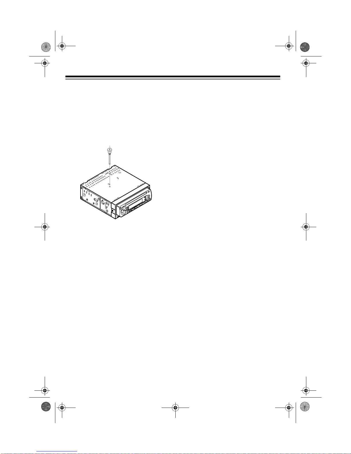
Removing the Shipping Screws
The shipping screws help protect the
stereo from be ing da maged d uring ship ment. Before you mount t he stere o, use
a Phillips screwdriver to remov e the two
screws from the top of the stereo.
Save the shipping screws in case
Note:
you ever want to ma il or s hi p the ste r eo.
You can secure them to the back of the
stereo with a piece of tape.
MAKING THE
CONNECTIONS
The supplied harness with the 14-pin
connector includes all the lead wires you
need to connect the stereo to ground,
power, some optional components, and
speakers.
Important:
you cut any wire, you cannot obtain a refund or exchange on this product. However, your local RadioShack store will
provide warranty service if you cut a
wire and find the product is defective.
Do not cut these wires. If
You might need additional wire, depending on your individual autosound system, to complete the conne ctions. Your
local RadioShack stor e carries a full lin e
of wire and wire manage ment accessories.
Cautions:
• For added safety and to protect your
stereo, disconnect the cable from
your vehicle battery's negative (–)
terminal before you begin.
• Be sure your speakers can handle
120 watts of power (30 watts per
channel if you ar e u sing two pai rs o f
speakers). Each speaker must have
an impedance of at least 4 ohms.
Your lo cal RadioShac k store carri es
a full line of speakers.
• You must connect the GROUND (–),
+12V TO IGNITION, and +12V TO
BATTERY wires fi rst, then make all
other connections as described in
the following sections before you
plug the harness with the 14-pin
connector into the ste reo. If you do
not make connections in the order
shown, damage to the stereo is possible if any wire connections are
made incorrectly.
• You must connect a separate wire to
each speaker terminal as described
in the following procedure. Do not
use a common wire or chassis
ground for any speaker connection.
6

)
12-2156.fm Page 7 Wednesday, November 24, 1999 10:39 AM
• The stereo’s buzzer alarm s ounds if
you make an incorrect connection.
For example, speaker wires make
contact to ground and the battery’s
positive (+) terminal for around 5
seconds with the powe r leads connected to the battery’s positive terminal and the ground wire
connected to the battery’s negative
terminal.
Using an Adapter Harness
If you are replacing an existing stereo,
or if your vehicle has been fac tory-wired
for autosound components, you might
be able to use an adapter harness to
connect the power and speakers. RadioShack stores sell adapter harnesse s
for most vehicles.
Follow the direction s that come with the
adapter harness to tempo rarily connect
the ground, power optional components,
and speakers. Then go to “Completing
the Connections” on Page 9.
Follow these steps to connect the harness with the 14-pin connector to
ground, primary and memory backup
power, and optional components.
1. Disconnect the cable from your
vehicle's negative ( –) battery terminal.
2. Connect the black ground wire to a
chassis ground, such as a metal
screw attached to a metal part of the
vehicle's frame. Be sure that the
screw is not insulated from the
chassis by a plastic part.
3. Connect the red po wer wire (with filter and fuse box) to a point in your
vehicle's fuse block that has power
only when you turn the vehicle's key
to either the accessory (ACC) or ON
position. This connection turns on
the stereo when you turn on the ignition or turn the key to ACC, and
turns off the stereo when you turn
off the ignition. This prevents your
vehicle's battery from being drained
if you leave the stereo o n when you
turn off the ignition.
Connecting Ground, Power,
and Optional Components
Black GROUND (–
Red +12V
TO IGNITIO N
Yellow +12V
To BATTERY
Blue/White
AMP REMOTE
TURN ON
500MA MAX
4. Connect the yellow power/memory
wire (with filter and fuse box) to your
vehicle battery's positive (+) terminal or to a point in your vehicle's
fuse block that provides a continuous source of 12 volts.
This connection p rovides power for
the stereo's components, and continuous power for the st ereo's me mory when the ignition is turned off.
7

12-2156.fm Page 8 Wednesday, November 24, 1999 10:39 AM
5. Connect the blue/white wire to any
optional equipment , designe d to run
from a switched source, that you
want the stereo to turn on and off
(such as a booster or a power
antenna).
This wire does not provide p ower to
the components. If you do not use
this wire, secure it with a wire tie
and do not let it touch metal.
Testing the Power Connections
Temporarily connect:
• The harness to the stereo's 14-pin
wiring socket
• Your vehicle battery's negative (–)
cable
Turn on your vehicle's ignition and install
your stereo's control panel (se e “Installing/Removing the Control Panel” on
Page 11). Verify that the stereo works
properly when the display lights.
If the display d oes not l ig ht, i mme dia tel y
turn off your vehicle's ignition and disconnect your vehicle battery's negative
(–) cable. Then recheck your connections.
Connecting an Equalizer/
Booster
If you are connecting the stereo to a
separate equalize r or boos ter, you nee d
additional wires (not included).
To increase the total power output from
your system, connect an equalizer or
booster to the
R
(right) and L (left) line
output jacks on the back of the stereo
(and the 14-pin connector’s blue/white
wire, if you want to use the stereo to turn
on and off the equalizer or booster).
Line Output Jacks
Booster
Blue-White AMP REMOTE
TURN ON 500MA MAX
Check the equalizer/booster's owner's
manual for directions.
Connecting Two Pairs of
Speakers
If the stereo wo rks proper ly, remov e the
control panel and disconnect:
• Your vehicle battery's negative (–)
cable
• The harness from the stereo's 14pin wiring socket
Then proceed with the installation.
8
Follow these steps to connect the harness with the 14-pin connector to the
speakers.
1. Connect the white wire to the left
front speaker's positive terminal.
This terminal is usual ly marked with
a plus (+) sign or red mark.
 Loading...