

Page 1
ION450
Ion Analyser
D21M079
Reference Manual
Page 2

D21M079 • Printed by Radiometer Analytical SAS • 2005-02B
Page 3

MeterLab
®
ION450 Reference Manual
Contents
Contents..................................................................................................................3
Introduction ..........................................................................................................11
Read me! ...............................................................................................................12
Practical examples ..............................................................................................15
Programming electrodes ...........................................................................................17
Programming methods ..............................................................................................23
Programming sequences ...........................................................................................27
Programming tips ................................................................................................29
Glossary ...............................................................................................................31
Accept a result ............................................................................................................33
Acceptance criteria ....................................................................................................33
Acceptation .................................................................................................................34
Access routine mode .................................................................................................34
Active electrode unknown in "method ID" ...............................................................34
Add method menu ......................................................................................................35
Address .......................................................................................................................35
Alarm: Locked .............................................................................................................35
Alarm: Unlocked .........................................................................................................35
Alphanumeric characters ..........................................................................................36
Applied signal (AC/DC) ..............................................................................................36
Archives data lost - Cal. Data lost - Methods kept ..................................................36
Archiving .....................................................................................................................37
Assistant function ......................................................................................................37
Autochaining ...............................................................................................................38
Auxiliary input .............................................................................................................39
Auxiliary output ..........................................................................................................40
Aux. on for ...................................................................................................................40
Bar code reader connection ......................................................................................40
Beaker menu ...............................................................................................................41
Beakers: [F;L] .............................................................................................................41
Beep .............................................................................................................................42
C0 (Detection limit) .....................................................................................................42
Cable capacity ............................................................................................................43
Cable resistance .........................................................................................................44
Calibrate conductivity cells .......................................................................................45
Calibrate ISE electrodes ............................................................................................45
Page 3
Page 4

MeterLab
Calibrate pH electrodes .............................................................................................45
Calibration = Manual ..................................................................................................46
Calibration curve of an ISE electrode .......................................................................47
Calibration delay elapsed ..........................................................................................47
Calibration parameters ..............................................................................................47
Calibration request/Calibration .................................................................................47
Calibration request = Fixed .......................................................................................48
Calibration request = Free .........................................................................................49
Calibration stack .........................................................................................................49
Calibration results parameters ..................................................................................49
Catalogue list ..............................................................................................................49
Cell constant (parameter) ..........................................................................................50
Cell constant (definition) ...........................................................................................51
Cell grounding ............................................................................................................51
Cell window .................................................................................................................52
Change electrode name .............................................................................................52
Change method name ................................................................................................52
Change sequence name ............................................................................................52
Check command .........................................................................................................53
Check electrodes ........................................................................................................53
Concentration x ..........................................................................................................54
Concentration unit ......................................................................................................54
Conductivity cell .........................................................................................................54
Conductivity cell calibration ......................................................................................54
Conductivity measurement method .........................................................................55
Configuration menu ...................................................................................................56
Connections ................................................................................................................56
Connect electrodes ....................................................................................................56
Contrast .......................................................................................................................56
Controlled by TTL IN ..................................................................................................56
Copy electrode ............................................................................................................57
Copy method ...............................................................................................................58
Coupled method .........................................................................................................58
Create electrode .........................................................................................................59
Create method ............................................................................................................60
Current value ..............................................................................................................60
Curve ...........................................................................................................................60
Curves data lost - Cal. Data kept - Methods kept ....................................................60
Customise ...................................................................................................................61
Date entry ....................................................................................................................61
Default parameters .....................................................................................................61
®
ION450 Reference Manual
Page 4
Page 5

MeterLab
Delete electrode ..........................................................................................................62
Delete method .............................................................................................................62
Demand: Locked .........................................................................................................62
Demand: Unlocked .....................................................................................................63
Detailed ........................................................................................................................64
Detection limit (C0) .....................................................................................................64
Direct ISE measurement method - definition ...........................................................65
Direct ISE measurement method - notes .................................................................66
Direct ISE measurement method - programmation .................................................66
Direct measurements .................................................................................................66
Disconnect electrodes ...............................................................................................67
Display contrast ..........................................................................................................67
Display measurement ................................................................................................68
E0 standard potential .................................................................................................68
EC socket ....................................................................................................................69
EC/pH measurement method - definition .................................................................70
EC/pH measurement method - programmation .......................................................71
Edit electrode menu ...................................................................................................72
Edit method menu ......................................................................................................73
Edit sequence menu ...................................................................................................74
Electrode calibration (Fixed mode, conductivity cell) .............................................75
Electrode calibration (Free mode, conductivity cell) ..............................................76
Electrode calibration (ISE) .........................................................................................77
Electrode calibration (Fixed mode, pH electrode) ...................................................78
Electrode calibration (Free mode, pH electrode) .....................................................79
Electrode calibration (sequence) ..............................................................................80
Electrode calibration not required ............................................................................80
Electrode calibration parameters ..............................................................................81
Electrode calibration stack ........................................................................................82
Electrode connection .................................................................................................83
Electrode connection - Important .............................................................................84
Electrode function ......................................................................................................84
Electrode icons ...........................................................................................................85
Electrode ID .................................................................................................................85
Electrode library .........................................................................................................86
Electrode not calibrated .............................................................................................86
Electrode system ........................................................................................................86
Electrode type .............................................................................................................87
Electrode window .......................................................................................................88
Empty sequence .........................................................................................................88
Error - Error messages ..............................................................................................89
®
ION450 Reference Manual
Page 5
Page 6

MeterLab
Fixed (calibration mode) ............................................................................................89
Format (printouts) ......................................................................................................90
Free beakers ...............................................................................................................90
Free (calibration mode) ..............................................................................................90
Function ......................................................................................................................91
Fuses ...........................................................................................................................91
GLP-Archives menu ...................................................................................................92
Ground conflict ...........................................................................................................92
Help ..............................................................................................................................92
High (result indicator) ................................................................................................92
Icons ............................................................................................................................93
ID ..................................................................................................................................93
Input address conflict ................................................................................................93
Insert method menu ...................................................................................................94
Insufficient number of beakers .................................................................................94
ION cell external Gnd .................................................................................................94
ISE calibration results parameters ...........................................................................94
ISE calibration solutions ............................................................................................95
Iso pH ...........................................................................................................................95
Keyboard connection .................................................................................................96
Keyboard connection - Important .............................................................................97
Language .....................................................................................................................97
Linear (temperature correction) ................................................................................97
Low (result indicator) .................................................................................................97
Main window ...............................................................................................................98
Mains frequency .........................................................................................................98
Maintenance ................................................................................................................99
Manual (calibration mode) .........................................................................................99
Max. stab reached ....................................................................................................100
Max. stab time ...........................................................................................................100
Measurement ............................................................................................................100
Measurement method ..............................................................................................101
Method .......................................................................................................................101
Method library ...........................................................................................................102
Method parameters menu ........................................................................................102
Method results menu ...............................................................................................103
Method wrong type ...................................................................................................103
Min. cell cst - Max. cell cst .......................................................................................103
Min. pH0(25) - Max. pH0(25) .....................................................................................104
Min. sensitivity - Max. sensitivity ............................................................................104
Min. Temp. - Max. Temp. ..........................................................................................104
®
ION450 Reference Manual
Page 6
Page 7

MeterLab
Minimum value - Maximum value ............................................................................105
Mode ..........................................................................................................................105
Molar weight ..............................................................................................................105
Nat. water (temperature correction) ........................................................................106
Nb lines per page (printouts) ...................................................................................106
None (temperature correction) ................................................................................106
Notification message ...............................................................................................106
Number of beakers ...................................................................................................106
Number of buffers ....................................................................................................107
Number of cycles ......................................................................................................107
Number of decimals .................................................................................................107
Number of digits .......................................................................................................107
Number of rinses ......................................................................................................108
Number of solutions .................................................................................................108
Number of tests ........................................................................................................108
OK (result indicator) .................................................................................................108
Others list ..................................................................................................................109
Parameters menu .....................................................................................................109
PC cable - A95X501 ..................................................................................................109
PC connection ..........................................................................................................109
PC keyboard ..............................................................................................................109
Periodicity .................................................................................................................110
Periodicity for QC samples ......................................................................................110
pH0(25) ......................................................................................................................110
pH buffer ....................................................................................................................111
pH int .........................................................................................................................111
Potential versus SHE ...............................................................................................112
Preprogrammed list ..................................................................................................112
Printer ........................................................................................................................113
Printer cables - A95P201, A95X506 .........................................................................114
Printer connection ....................................................................................................115
Print in table ..............................................................................................................115
Printouts ....................................................................................................................116
Printouts detailed .....................................................................................................116
Printouts menu .........................................................................................................117
Printouts setup .........................................................................................................117
Printouts title ............................................................................................................117
Programming method ..............................................................................................118
Programming sequence ...........................................................................................119
QC (result indicator) .................................................................................................120
QC analysis required ................................................................................................120
®
ION450 Reference Manual
Page 7
Page 8

MeterLab
QC data menu ...........................................................................................................120
QC ID ..........................................................................................................................120
QC not required ........................................................................................................120
QC periodicity elapsed .............................................................................................121
QC sample .................................................................................................................121
QC sample (Yes/No) .................................................................................................121
Ref. electrode conflict ..............................................................................................121
Reference Temp. .......................................................................................................121
Reject a result ...........................................................................................................121
Remove method from a sequence ..........................................................................122
Replace electrodes ...................................................................................................122
Reset memory ...........................................................................................................122
Reset to factory settings ..........................................................................................122
Result accepted (Yes/No) ........................................................................................123
Result indicators ......................................................................................................124
Result unit .................................................................................................................124
Results .......................................................................................................................125
Results factor (Yes/No) ............................................................................................126
Results menu ............................................................................................................126
Rinse aux. output .....................................................................................................127
Rinse time .................................................................................................................127
Routine mode ............................................................................................................127
Run window ..............................................................................................................128
Run window (continued) ..........................................................................................129
Running a method/sequence ..................................................................................130
SAC80/SAC90 ...........................................................................................................131
SAC80/SAC90 cable - A95A202 ...............................................................................131
SAC ext. cell GND .....................................................................................................131
SAC Method ..............................................................................................................131
SAC Sequence ..........................................................................................................131
Same buffer change buffer ......................................................................................132
Sample changer ........................................................................................................132
Sample ID ..................................................................................................................132
Sample stack .............................................................................................................133
Select electrode ........................................................................................................134
Select method ...........................................................................................................134
Select sequence .......................................................................................................134
Sensitivity ..................................................................................................................135
Sequence/SAC sequence ........................................................................................135
Serial number (of an electrode) ...............................................................................136
Setup menu ...............................................................................................................136
®
ION450 Reference Manual
Page 8
Page 9

MeterLab
Skip empty position .................................................................................................136
Software version .......................................................................................................136
Solution menu ...........................................................................................................137
Stability ......................................................................................................................138
Standard (conductivity standard) ...........................................................................139
Standard potential ....................................................................................................140
Standard solution (conductivity measurements) ..................................................140
Standard solution (ISE measurements) .................................................................140
Statistics ....................................................................................................................140
Stirring .......................................................................................................................141
Stop analysis ............................................................................................................142
Supervisor code .......................................................................................................143
Supervisor mode ......................................................................................................144
T°C minimum/maximum value ................................................................................144
Temp. coef. ................................................................................................................144
Temp. correction None/Linear/Nat. water ..............................................................145
Temp. limit exceeded ...............................................................................................146
Temperature Probe/ Fixed at 25°C/Entered ............................................................146
Temperature sensor ID ............................................................................................147
The sequence is empty ............................................................................................147
Time max (result indicator) ......................................................................................147
Title ............................................................................................................................147
TTL 5 V OUT/TTL 12 V OUT (sockets) .....................................................................148
TTL IN (sockets) .......................................................................................................148
Type of method .........................................................................................................148
User ID (Yes/No) .......................................................................................................149
User list .....................................................................................................................149
User’s rights ..............................................................................................................149
Valency ......................................................................................................................150
Working mode ...........................................................................................................150
Wrong buffer .............................................................................................................150
Zero pH ......................................................................................................................150
®
ION450 Reference Manual
Appendixes ........................................................................................................151
Appendix 1: Preprogrammed methods ..................................................................153
Appendix 2: General information ............................................................................155
Appendix 3: Result calculations .............................................................................157
Appendix 4: Technical specifications ....................................................................167
Page 9
Page 10

MeterLab
®
ION450 Reference Manual
Page 10
Page 11

MeterLab
®
ION450 Reference Manual
Introduction
The ION450 Ion Analyser is dedicated for routine use. It offers two distinct user levels:
• Supervisor
Dedicated for operators who wish to edit their methods to fit their specific needs. They can
also assign a password to protect the programmed data from eventual changes.
•Routine
Dedicated for operators wishing to use the routine functions to guide them step by step
through the analyses.
The ION450 can store up to 50 methods and 30 electrodes. In addition 30 electrodes have
been pre-defined to help you save time setting up your application.
Thanks to the preprogrammed applications, the Ion Analyser is ready for use as soon as it has
been installed. Refer to "Appendix 1: Preprogrammed methods", page 153..
The ION450 also allows you to automatically sequence and repeat measurements.
The purpose of the ION450 Reference Manual is to give detailed information on the
Ion Analyser and the data displayed during operations. The information is listed in
alphabetical order for quick access and cross-references are listed in italics.
In addition to this handbook, a general User’s Guide (part no. D21M075) is available giving
descriptions and overviews of the workstation menus and operating concepts to guide you
through programming and running of the analyses.
Page 11
Page 12

MeterLab
®
ION450 Reference Manual
Read me!
An important feature of this instrument interface is that it controls the presence of different
elements necessary to run the defined application for a selected method/sequence, before the
method/sequence is run.
Working in Supervisor mode
A Supervisor has access to all the libraries for creation purposes.
When programming the instrument in “SUPERVISOR” mode, it is recommended to work in
stages. These stages must be carried out in the order described below:
A.To program method
1. Define your electrode(s)
Identify electrodes (including temperature sensors) to be used for the analysis:
Electrodes can be created from the following lists:
Catalogue, see "Catalogue list", page 49.
Other, see "Others list", page 109.
Copy from, see "Copy electrode", page 57.
When creating the electrode, define if electrode calibration is required (or not), if yes specify
the "periodicity" of the calibrations and the pH, ISE or conductivity standards to be used.
Refer to "Calibrate pH electrodes", page 45.
Refer to "Calibrate ISE electrodes", page 45.
Refer to "Calibrate conductivity cells", page 45.
2. Create new method or Edit a pre-programmed one
Create the method to be used for the analyses. Enter the parameters required to calculate the
results, see "Programming methods", page 23.
When you have finished programming, select the method/sequence or pre-programmed
application, see "Select method", page 134. or see "Select sequence", page 134.
If your methods are to be performed in a sequence, program the sample stack, see "Sample
stack", page 133.
Page 12
Page 13
MeterLab
®
ION450 Reference Manual
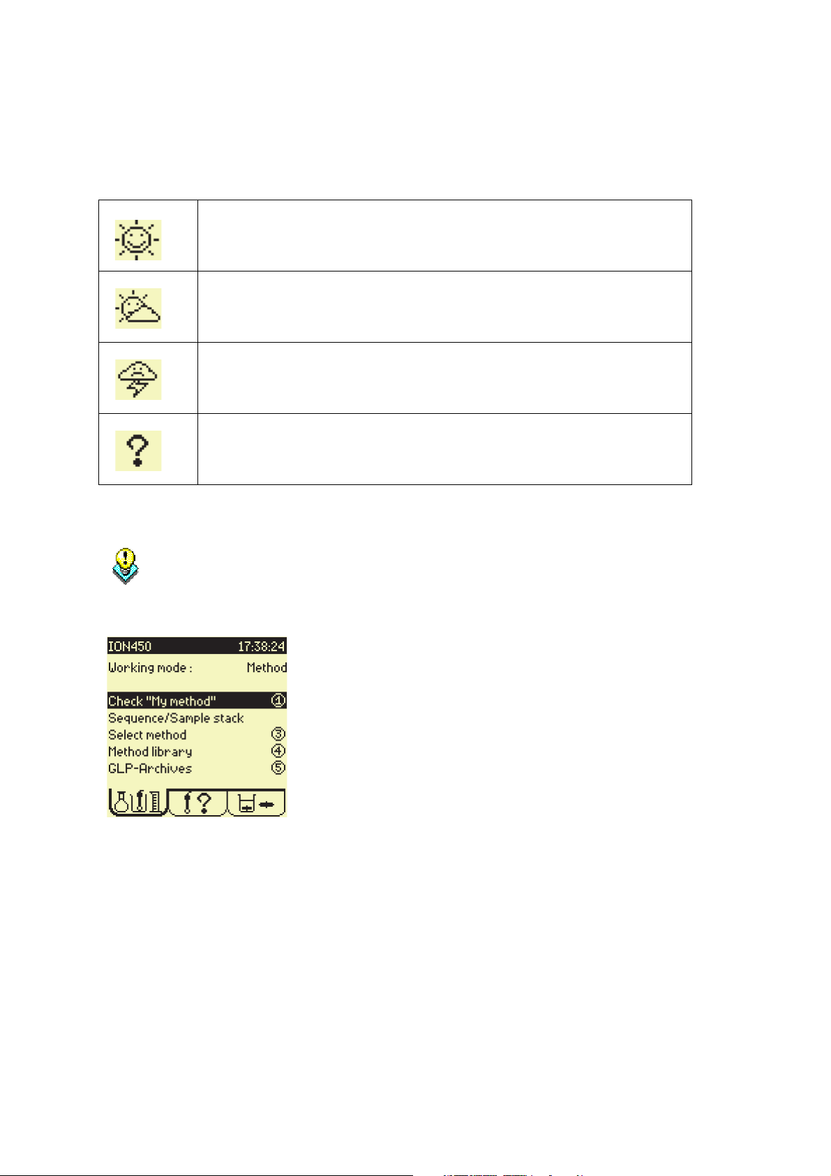
3. Check icons
The following icons indicate the exact state of your working system:
Sunny icon:
Everything is OK. Run the method or sequence.
Cloudy icon:
Electrode calibration is required within 12 or 24 hours.
Stormy icon:
Electrode calibration date elapsed or electrodes not installed.
Question mark:
Programming error.
Refer to "Electrode icons", page 85.
A Sunny icon is needed in order to run the selected method.
If a Cloudy/Stormy/Question mark icon is displayed in the Electrode window press 1
to activate the “Check” command. The ION450 will automatically guide you through
the operations required to solve the errors encountered.
B.Running methods
To run a method or sequence, see "Working in Routine mode", page 14.
Page 13
Page 14
MeterLab
®
ION450 Reference Manual
Working in Routine mode
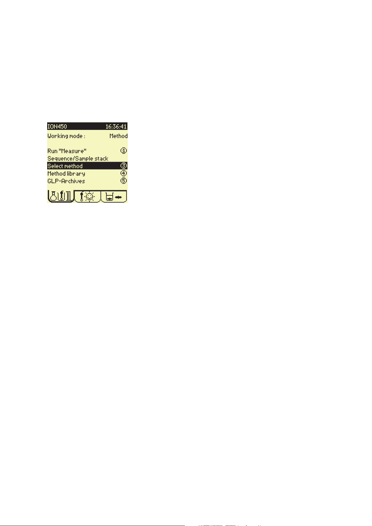
A.Access methods
A Routine operator has access to all the methods “Select method” and programmed
parameters “Display method” for checking purposes
B.Running methods
When working in “ROUTINE” mode, it is necessary to install your measurement system
according to the selected method or sequence, prior to running a method or sequence.
1. Select the method or sequence
Refer to "Select method", page 134.
Refer to "Select sequence", page 134.
2. Check icons
Refer to "Check icons", page 13.
Depending on the icon displayed, the ION450 will automatically guide you through the steps
necessary to run the analysis, see below:
a. Connect the electrode(s)
Connect/install electrodes and temperature sensors, Refer to "Electrode connection",
page 83.
b. Calibrate electrode(s)
Now, run the calibration.
Refer to "Calibrate pH electrodes", page 45.
Refer to "Calibrate ISE electrodes", page 45.
Refer to "Calibrate conductivity cells", page 45.
c. Run the method or the sequence
Refer to "Running a method/sequence", page 130.
Page 14
Page 15

Practical examples
Page 16

Page 17
MeterLab
®
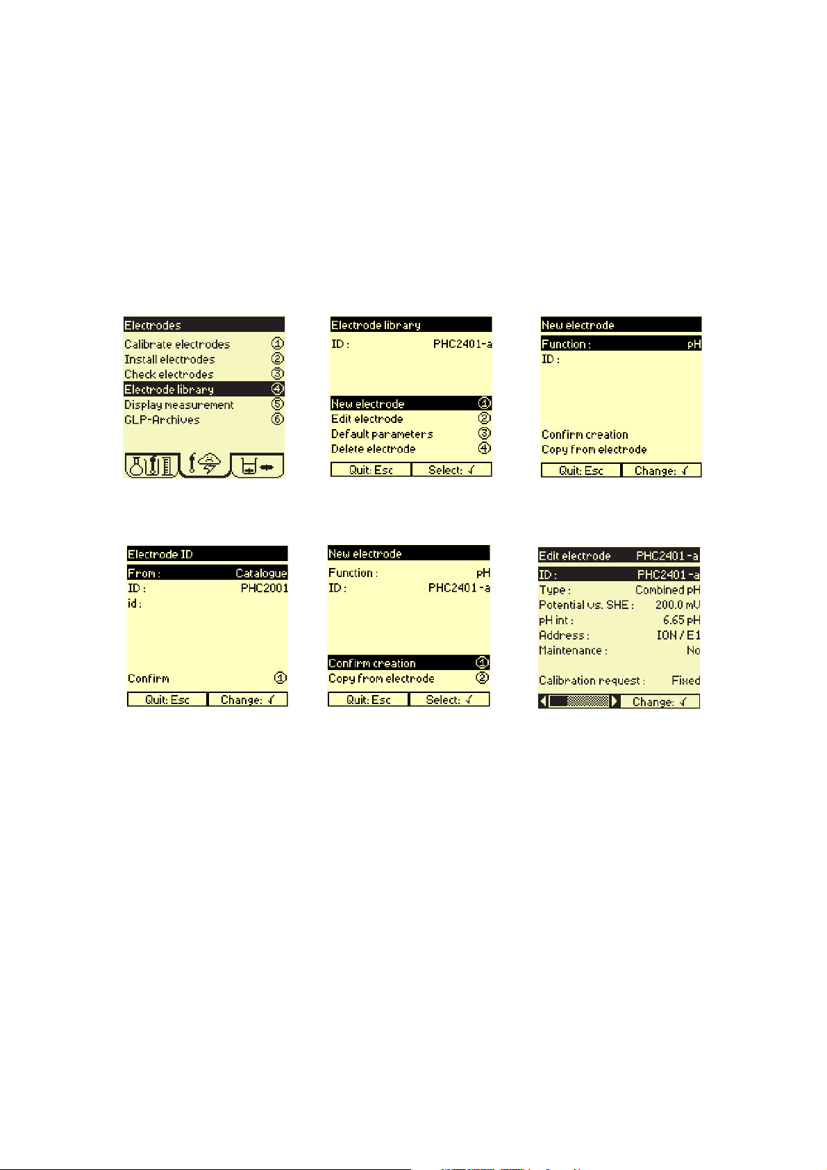
Programming electrodes
pH electrodes
ION450 Reference Manual
1.
Press 4.
4.
2.
Press 1.
5.
3.
Select function and ID.
6.
Select ID from Catalogue or
Others list.
Press 1 to confirm.
Press 1 to confirm the creation
of the new electrode.
For a combined or a simple or
reference electrode, enter the
potential (in mV) of the reference versus the Standard Hydrogen Electrode (SHE).
For a combined or a simple
electrode if you have selected
the Others list, enter the internal pH of the electrode.
Enter the electrode address.
If you want a message to be
displayed once a week concerning this electrode, select
Maintenance = Yes and enter
the message.
Select Fixed or Free if a calibration is required, go to step 7.
Select No, for no calibration,
press Esc to leave the menu.
Programming is completed.
Page 17
Page 18
MeterLab
Calibration request = Fixed
Calibration with automatic recognition of the buffer among a list of predefined values. The buffer
values are entered during method edition.
Calibration request = Free
The buffer values are entered FREEly by the user. Use this option to calibrate pH electrode with
buffers that do not belong to the predefined list.
®
ION450 Reference Manual
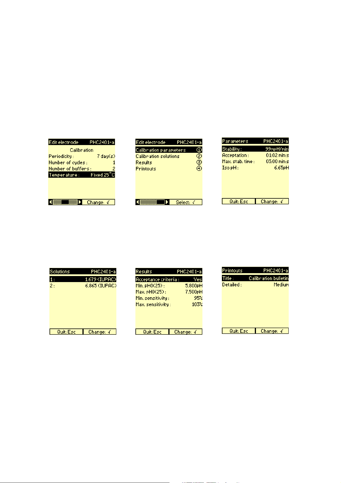
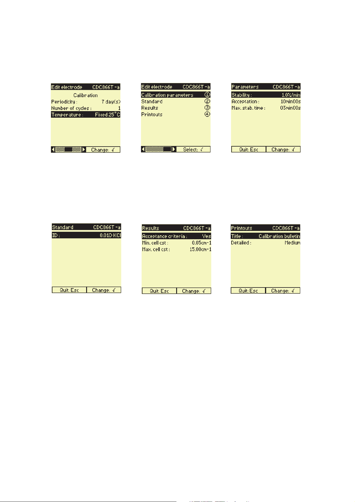
7.
Enter the calibration
parameters.
10.
8.
Press 1.
11.
9.
Enter the electrode calibration
parameters.
For a Fixed calibration, press
Esc then 2. Go to step 10.
For a Free calibration, press
Esc then 3. Skip to step 11.
12.
Fixed calibration only.
Select the buffer solutions
used. Press Esc then 3.
Page 18
Enter the results parameters.
Press Esc then 4.
Enter the printouts parameters.
Press Esc twice. Electrode
programming is completed.
Page 19
MeterLab
®
ISE electrodes
ION450 Reference Manual
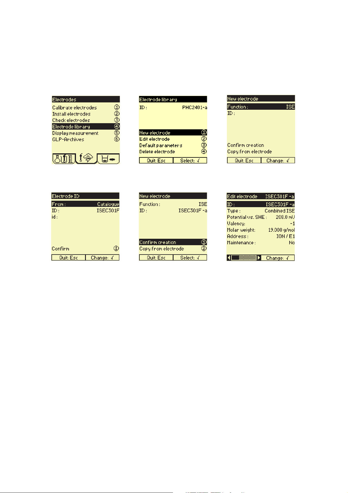
1.
Press 4.
4.
2.
Press 1.
5.
3.
Select function and ID.
6.
Select ID from Catalogue or
Others list.
Press 1 to confirm.
Press 1 to confirm the creation
of the new electrode.
For a combined or a simple or
reference electrode, enter the
potential (in mV) of the
reference versus the Standard
Hydrogen Electrode (SHE).
IfyouhaveselectedtheOthers
list, select the valency and
enter the molar weight of the
ion under study.
Enter the electrode address.
If you want a message to be
displayed once a week
concerning this electrode,
select Maintenance = Yes and
enter the message.
Press the Left or Down arrow
key.
Select Manual if a calibration is
required then go to step 7.
Select No, for no calibration,
press Esc to leave the menu.
Programming is completed.
Page 19
Page 20
MeterLab
Calibration = Manual
Calibration using 1 to 9 standards of known concentration.The standard concentrations are entered
during method edition. This method requires 1 to 9 calibration beakers.
®
ION450 Reference Manual
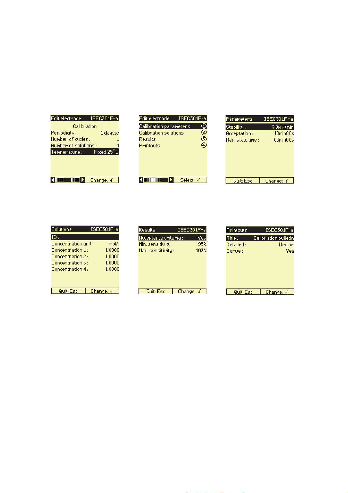
7.
Enter the calibration
parameters.
10.
8.
Press 1.
11.
9.
Enter the electrode calibration
parameters.
Press Esc then 2.
12.
Enter the standard solution ID
and standard concentrations.
Press Esc then 3.
Page 20
Enter the results parameters.
Press Esc then 4.
Enter the printouts parameters.
Press Esc twice. Electrode
programming is completed.
Page 21
MeterLab
®
Conductivity cells
ION450 Reference Manual
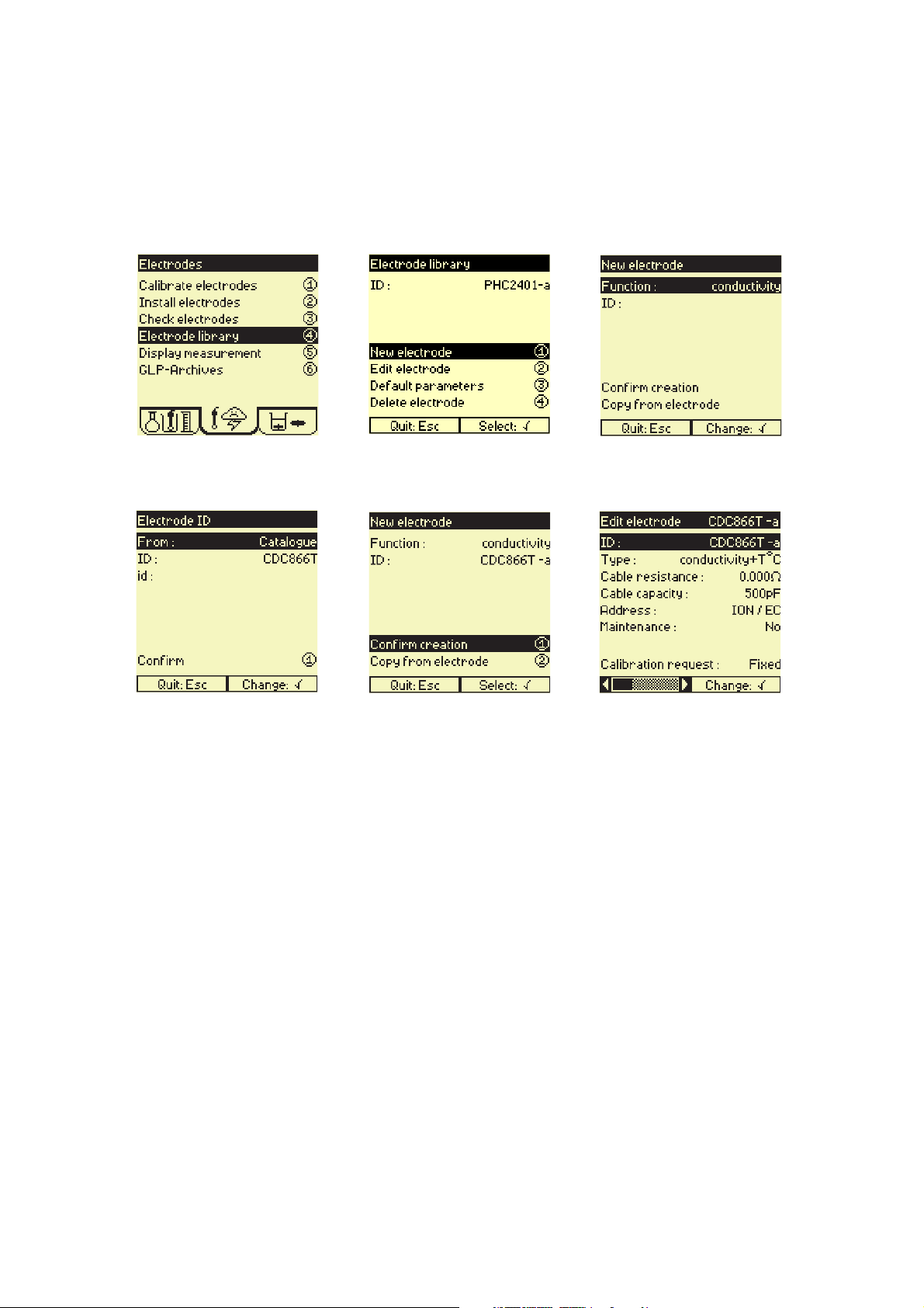
1.
Press 4.
4.
2.
Press 1.
5.
3.
Select function and ID.
6.
Select ID from Catalogue or
Others list.
Press 1 to confirm.
Calibration request = Free
Use the Free calibration mode when you use a standard that does not belong to the Catalogue list
and you know the conductance of this standard at a given temperature. During a Free calibration run
and after stabilisation of the measurement, you will adjust the cell constant in order to display the
correct conductance value.
Calibration request = Fixed
With the Fixed mode when you use a standard that belongs to the Catalogue list, the cell constant is
determined as the ratio of the conductivity (known by the instrument) divided by the measured
conductance.
Press 1 to confirm the creation
of the new electrode.
IfyouhaveselectedtheOthers
list, enter the cable resistance
and capacitance.
If you want a message to be
displayed once a week concerning this electrode, select
Maintenance = Yes and enter
the message.
Select Fixed or Free if a
calibration is required, go to
step 7.
Select No, for no calibration,
press Esc to leave the menu.
Programming is completed.
Page 21
Page 22
MeterLab
®
ION450 Reference Manual
7.
Enter the calibration
parameters.
10.
8.
Press 1.
11.
9.
Enter the electrode calibration
parameters.
For a Fixed calibration, press
Esc then 2. Go to step 10.
For a Free calibration, press
Esc then 3. Skip to step 11.
12.
Fixed calibration only.
Select the standard solution
used. Press Esc then 3.
Enter the results parameters.
Press Esc then 4.
Enter the printouts parameters.
Press Esc twice. Electrode
programming is completed.
Page 22
Page 23
MeterLab
®
Programming methods
Creating and editing a method
ION450 Reference Manual
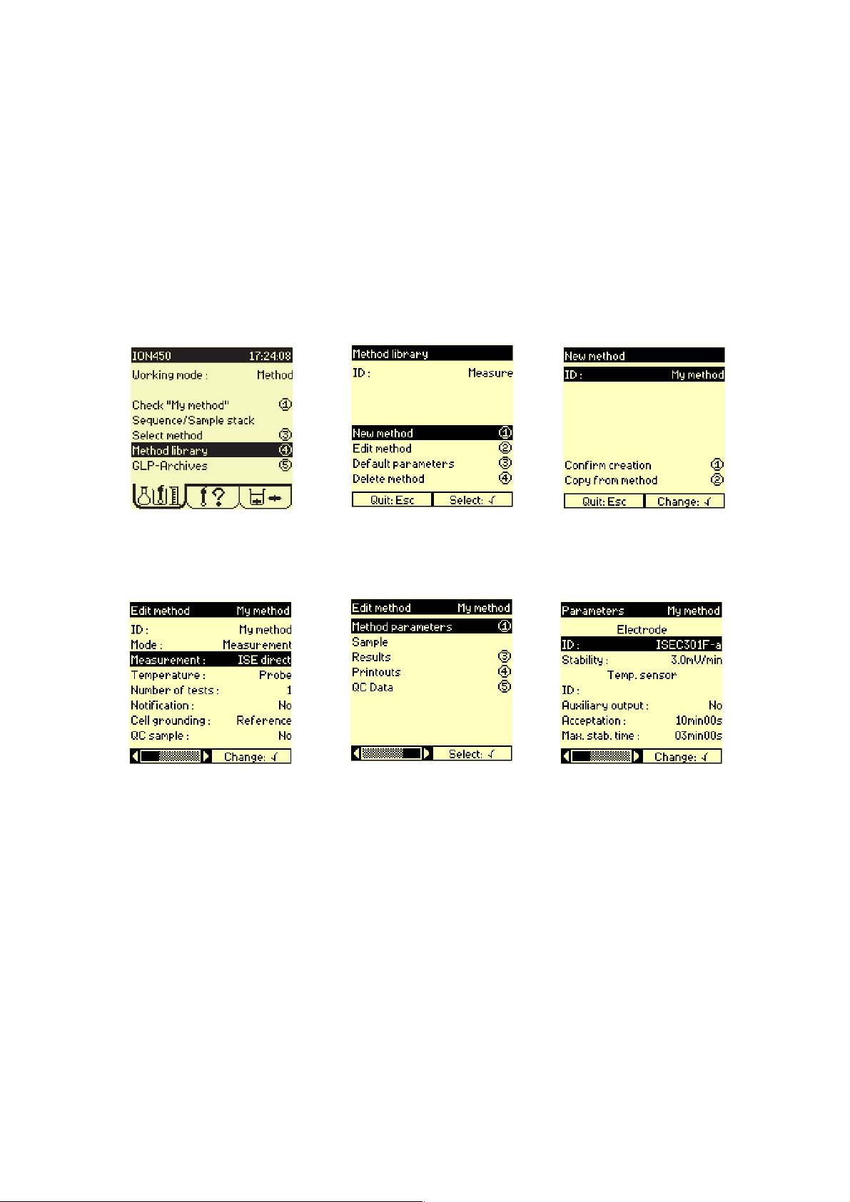
1.
Press 4.
4.
2.
Press 1.
5.
3.
Enter ID.
Press 1 to confirm.
6.
Enter method parameters.
Specify the Mode, see "Mode",
page 105.
Press 1.
Press ✓ and select the
electrode(s) and temperature
sensor from the lists.
Enter the other method
parameters.
Press Esc then 3.
Page 23
Page 24
MeterLab
®
ION450 Reference Manual
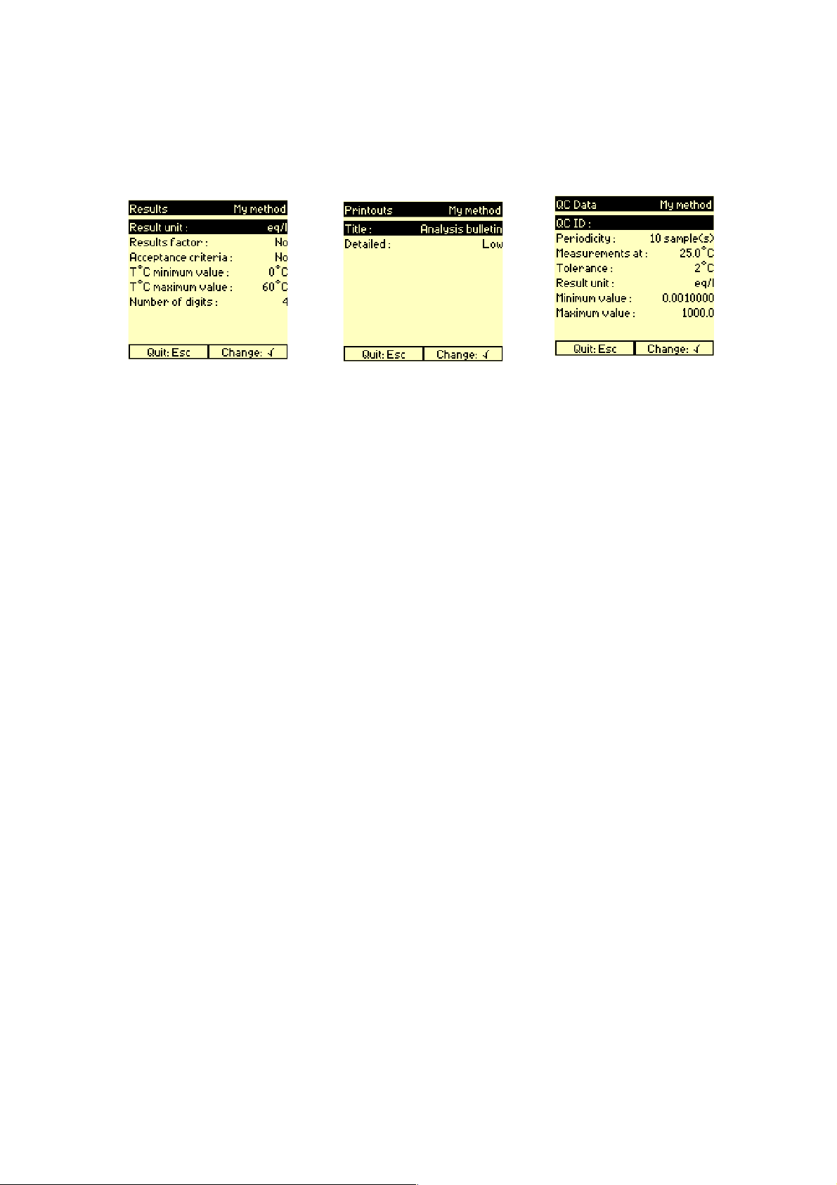
7.
Enter the results parameters.
Press Esc then 4.
8.
Enter the printouts parameters. If a QC sample has been
defined in step 4, press Esc
then 5.
9.
Enter the QC data. Press Esc
twice. Method programming is
completed.
Page 24
Page 25
MeterLab
®
For a Coupled method
ION450 Reference Manual
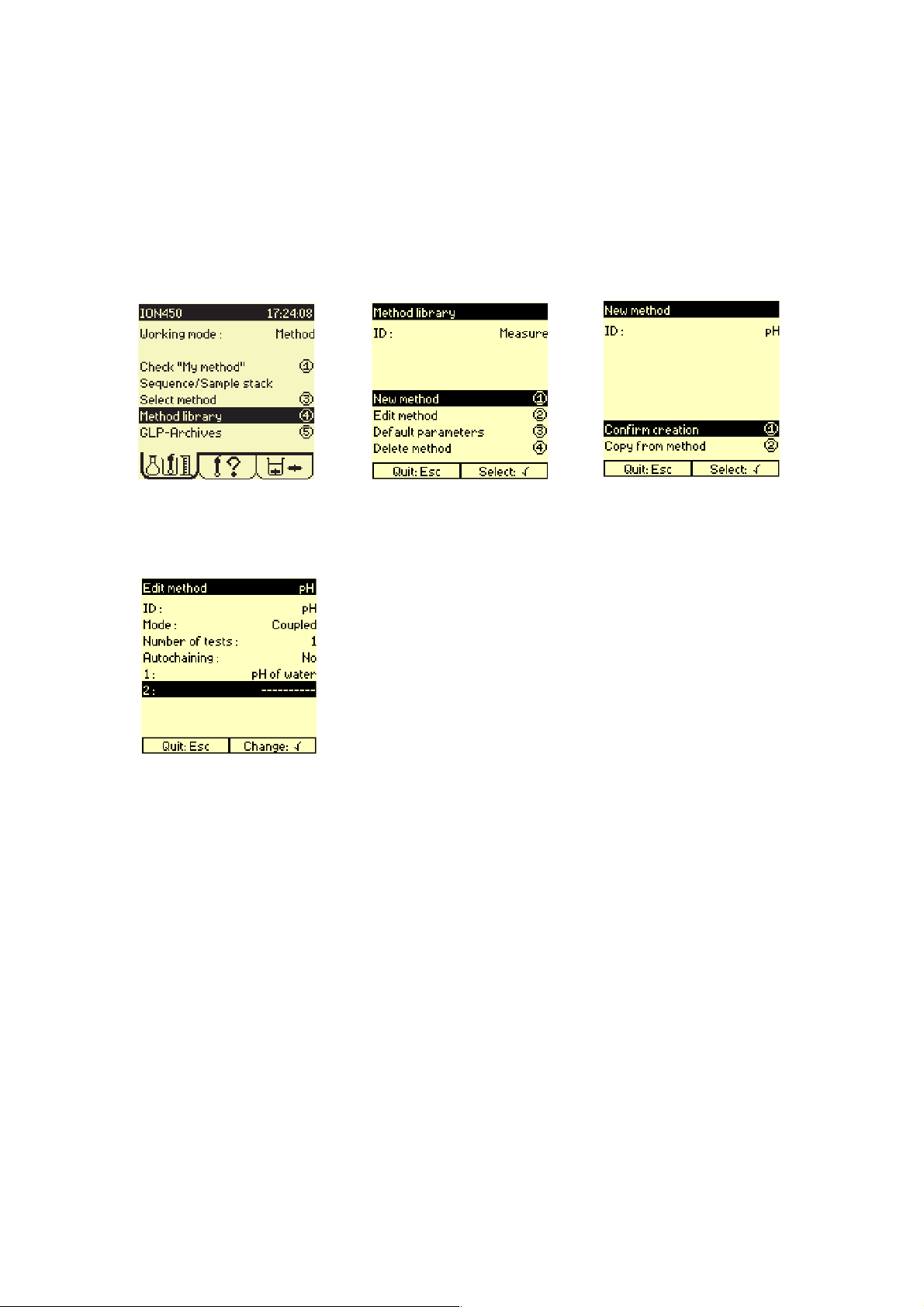
1.
Press 4.
4.
2
Press 1.
3.
Enter the Method ID and press
1 to confirm.
Select Mode = Coupled.
Enter the method to be linked.
Press Esc twice.
Method programming is
completed.
Page 25
Page 26

MeterLab
®
ION450 Reference Manual
Page 26
Page 27
MeterLab
®
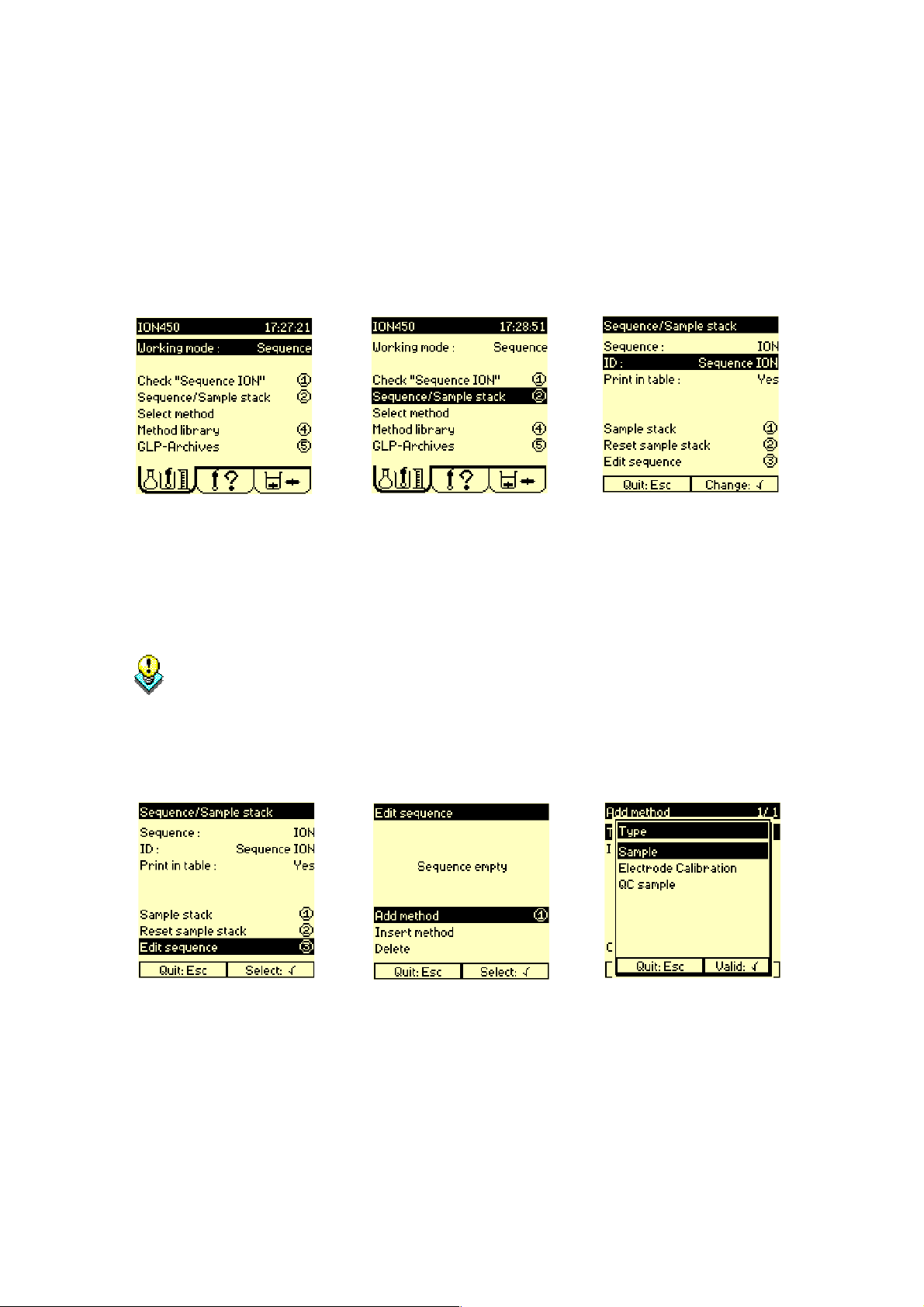
Programming sequences
ION450 Reference Manual
1.
Select:
Sequence:tocreatea
sequences of methods.
SAC Sequence:tocreatea
sequences of methods to be
performed using a Sample
Changer.
Define the Sample
Changer in the
Configuration menu
before selecting SAC
Method or SAC
Sequence.
2
Press 2.
3.
Enter a name for the sequence.
4.
Press 3.
5.
Press 1 to add a method.
6.
Select the type of method.
Page 27
Page 28
MeterLab
®
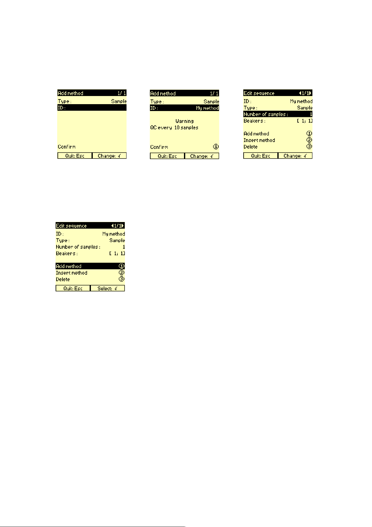
ION450 Reference Manual
7.
Selectamethodinthelistof
available methods.
10.
8.
Press 1 to add the method to
the sequence.
9.
If Sample has been selected in
step 6, enter the number of
samples (number of times you
wish to repeat the method in
the sequence).
Press 1 to add a second
method to the sequence.
Repeat steps 6 to 9.
Up to 10 methods can be
chained in a sequence.
After having added the last
method, press Esc twice.
Sequence programming is
completed.
Page 28
Page 29
MeterLab
®
ION450 Reference Manual
Programming tips
• Do not forget to declare electrode(s) when programming your method parameters
• If a Sample Changer is used, do not forget to declare one in the Configuration menu.
• If a printer is used, do not forget to declare one in the Configuration menu.
If no sun icon appears after the method has been selected, check the following points:
1. Install electrode(s) for selected method, see "Check electrodes", page 53.
2. If required, calibrate electrode.
Refer to "Calibrate pH electrodes", page 45..
Refer to "Calibrate ISE electrodes", page 45..
Refer to "Calibrate conductivity cells", page 45.
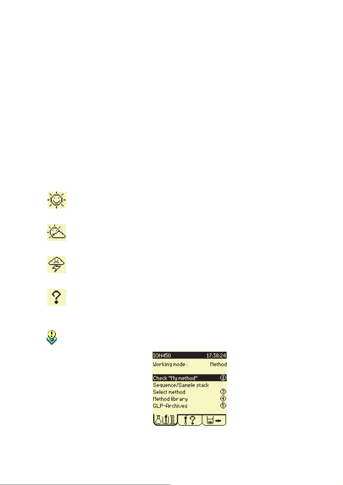
If a Sunny icon appears:
Everything is OK. A sunny icon is required to run the selected method.
If a Cloudy icon appears:
An electrode calibration should be performed within 24 hours.
This is a simple warning, it will not stop you from running the analysis.
If a Stormy icon appears:
Electrode required in the selected method is not installed. Electrode required in
the selected method has not been calibrated.
If a Question mark icon appears:
It is a programming error, electrode is not defined in the selected method. Revise
the method programming.
When a Stormy or a Question mark icon appears, press 1 “Check” . The ION450
will automatically guide you through the operations necessary to solve the errors
encountered.
Page 29
Page 30

MeterLab
®
ION450 Reference Manual
Page 30
Page 31

Glossary
Page 32

Page 33

MeterLab
®
ION450 Reference Manual
Accept a result
Acceptance criteria
Refer to "Result accepted (Yes/No)", page 123.
Acceptance criteria = Yes
Enables the user to enter preset minimum and maximum values for
measurement results. If the result lies outside these values an alarm
message appears and the results are rejected by the instrument. The
Supervisor is the only person allowed to accept a result that has been
rejected by the instrument, see "Result accepted (Yes/No)", page
123.
Therefore, acceptance limits can be set on:
• the conductivity cell constant,
see "Min. cell cst - Max. cell cst", page 103.
• the result value such as a pH, a potential, a concentration,
see "Minimum value - Maximum value", page 105.
• the response slope of a pH or an ISE electrode,
see "Min. sensitivity - Max. sensitivity", page 104.
• the pH0 of a pH electrode,
see "Min. pH0(25) - Max. pH0(25)", page 104.
Acceptance criteria = No
The Supervisor or Routine user is free to accept/reject the results.
Enter in:
Edit method > Results
Edit method > QC data
Edit electrode > Results
Irrespective of the Yes or No option selected for the
Acceptance criteria parameter:
•Acceptance limits must be set for the sample or the
standard measured temperature,
see "Min. Temp. - Max. Temp.", page 104,
see "T°C minimum/maximum value", page 144.
•A minimum limit is set by the instrument for the concentration measured by an ISE Direct measurement method. This
limit is the C
see "Minimum value - Maximum value", page 105.
•A maximum limit is set by the instrument for the concentration measured by an ISE Direct method. This limit is set to
30
, see "Minimum value - Maximum value", page 105.
10
concentration,
0
Page 33
Page 34

MeterLab
®
ION450 Reference Manual
Acceptation
Access routine mode
Result acceptance time limit.
When the time entered for the Acceptation has elapsed the
measurement will be accepted whether stable or not.
For the signal to be accepted once the Acceptation has
elapsed, the Max. Stab. time must be greater than the
Acceptation time.
Enter in:
Edit method > Parameters menu
Edit electrode > Calibration parameters menu
Range available:
0 to 59:59 min:s
Press Stop for 3 seconds from the Main window then press 2.
These rules can be set by the Supervisor to allow the routine user
access to certain operations.
Active electrode unknown in "method ID"
Page 34
Enter in:
Setup menu > Access routine mode
The method in use, has at least one electrode which has not been
defined. Press ✓ and declare the electrode in the Electrode ID field of
the Method parameters screen.
Page 35

MeterLab
®
ION450 Reference Manual
Add method menu
Address
Use this menu to set the ID and type of method to be added to a
sequence.
In the title bar, x/y (eg. 1/1) indicates the position "x" of the method in
the sequence and "y" the total number of methods in the sequence.
When a sequence is created <1/1> is displayed.
To access:
Press 1 in the Edit sequence menu.
The position where the electrode is placed during operation:
The electrode address is defined using the format “ION/x” where “x”
corresponds to the socket.
For example ION/E1, indicates that the electrode is connected to E1
socket on the ION450.
Refer to "Electrode connection", page 83.
Alarm: Locked
Alarm: Unlocked
The user cannot bypass an electrode and/or QC sample analysis if the
last result obtained lies outside the acceptance range.
Enter in:
Setup menu > Access routine mode
Enables the user to bypass an electrode and/or QC sample analysis
when the last result obtained lies outside the acceptance range.
Enter in:
Setup menu > Access routine mode
Page 35
Page 36

MeterLab
®
ION450 Reference Manual
Alphanumeric characters
The following alphanumeric characters can be obtained using the
ION450s Keypad:
Keys Characters
7 7,A,B,C,a,b,c,@
8 8,D,E,F,d,e,f
9 9,G,H,I,g,h,i
4 4,J,K,L,j,k,l
5 5,M,N,O,m,n,o,µ
6 6,P,Q,R,p,q,r
1 1,S,T,U,s,t,u
2 2,V,W,v,w
3 3,X,Y,Z,x,y,z
0 0,-,+,*,^,=,#,<,>,.
space, /, (, ), [, ], |, ?, !, %, °
Applied signal (AC/DC)
Archives data lost - Cal. Data lost - Methods kept
Table 1: Entering alphanumeric characters
Specifies the current type (alternative AC or direct DC) to be sent to
the Pt-Pt socket on the Ion Analyser. The AC signal frequency is
1.67 Hz. This option is available if mV(i>0) has been selected for
Measurement in the Edit method menu.
Enter in:
Method parameters menu
Instrument internal failure. Only the method parameters have been
kept.
Page 36
Page 37

MeterLab
®
ION450 Reference Manual
Archiving
Assistant function
Archiving = Yes (default setting)
All measurements (sample and electrode calibrations) are saved in the
archives. You can view these measurements as follows:
• Sample results: enter Main window and press 5
• Electrode calibration results: enter Electrode window and press 6
Refer to "GLP-Archives menu", page 92.
Archiving = No
No measurements are saved in the archives. The instrument saves
only the last electrode calibration.
When you set Archiving from No to Yes, you must recali-
brate your electrodes!
Enter in:
Setup menu > Configuration menu
Embedded instructions on the ION450 display to guide the user stepby-step through electrode installations. These instructions appear at
the start of a run method if the working system has not been correctly
installed.
By default this option is set to Yes. It is recommended to use
the default setting at all times!
If the setting is set to No, the ION450 considers that the working
system is correctly installed at the start of a run method.
However, this may not be the case, the user must know the status of
the working system at all times!
Enter in:
Setup menu > Configuration menu
Page 37
Page 38

MeterLab
®
ION450 Reference Manual
Autochaining
This option is valid for a Coupled method which is not part of a
sequence.
Autochaining = No
At the end of each method run, you must confirm the result in order to
perform the next method. If a Notification message has been selected,
a message is displayed between each method of the Coupled
method.
Autochaining = Yes
At the end of each method run, The methods are chained
automatically in the Coupled method. If a Notification message has
been selected, a message is displayed upon starting the first method
(no message is displayed after).
Refer to "Notification message", page 106.
Enter in:
Edit method menu (for a Coupled method)
Page 38
Page 39

MeterLab
®
ION450 Reference Manual
Auxiliary input
The auxiliary input socket can be connected to an external device unit
used to send an analysis start command to the ION450. The analysis
is a sequence of methods with manual change of the sample beakers
(Working mode = Sequence, see "Working mode", page 150).
The external device unit is to be connected to the red and black IN
banana sockets of the ION450. The red banana socket receives the
TTL 0 ± 5 V auxiliary signal and the black banana socket is connected
to the instrument electrical zero.
Proceed as follows to trigger a sequence of methods by an auxiliary
signal input:
• In the Configuration menu, select
Controlled by TTL IN = Yes.
• Connect the auxiliary control unit to red and black IN banana
sockets of the ION450.
• Run the sequence. The ION450 displays a waiting for auxiliary
signal message. The sequence is started as soon as the auxiliary
signal is received.
Spécifications of the auxiliary input signal
Refer to "TTL IN (sockets)", page 148.
Page 39
Page 40

MeterLab
®
ION450 Reference Manual
Auxiliary output
The auxiliary outputs are used to control external equipment such as
valves or pumps during analyses. This signal is sent between the red
and black banana sockets 5V OUT or 12V OUT of the ION450.
Auxiliary output (5 V, 12 V, No)
Activate to 5 V or 12 V or disable the auxiliary signal.
Specifications of the auxiliary ouput signal:
see "TTL 5 V OUT/TTL 12 V OUT (sockets)", page 148.
Aux. on for
Time during which the auxiliary signal is set to 5 V or 12 V.
Enter in:
Method parameters menu
Range available:
Aux. on for: 0 to 99:59 min:s
An auxiliary output can be activated:
•at the measurement start (duration set by Aux. on for)
•or during the whole measurement including measurement
stabilisation delay. In this case, select a 5 V or 12 V auxiliary
output and set Aux. on for = 0.
Aux. on for
Bar code reader connection
Refer to "Auxiliary output", page 40.
Connect a bar code reader to the ION450 via the 6-pin mini DIN port
situated on the right hand side of the instrument.
Page 40
Page 41

MeterLab
®
ION450 Reference Manual
Beaker menu
Use this menu to prepare a sample or calibration stack. This menu
defines individual data for all the samples or standards used in the
sequence.
Figure 1: Beaker menu (for a sample stack)
To access (for a sample stack):
1. Select Working mode = Sequence or SAC Sequence in the Main
window.
2. Press 2 Sequence/Sample stack.
3. Press 1 Sample stack.
Beakers: [F;L]
The sequence must have been edited in the Edit sequence
menu beforehand. Refer to "Edit sequence menu", page 74.
To access (for an electrode calibration stack):
1. Select Working mode = SAC Sequence in the Main window.
2. In the Electrode window, press 1 Calibrate electrodes.
3. Press 2 Calibration sequence.
The electrode calibration method must have been edited
beforehand. Refer to "Edit electrode menu", page 72.
Refer to "Sample stack", page 133.
Refer to "Electrode calibration stack", page 82.
The beakers information is displayed in the Edit sequence menu of a
sequence.
It indicates the First and Last positions occupied by the beakers in the
sequence.
Page 41
Page 42

MeterLab
®
ION450 Reference Manual
Beep
C0(Detection limit)
If Yes has been selected, three beeps will sound when a result is
obtained.
Enter in:
Setup menu > Configuration
Refer to "Direct ISE measurement method - definition", page 65.
Page 42
Page 43

MeterLab
®
ION450 Reference Manual
Cable capacity
A cable of a given length has a given capacity. When the measured
conductance is low (below 4 µS), the cable capacity is not
negligible and must be taken into account.
Enter the cable capacity when:
• measuring low conductances (below 4 µS),
• the cable capacity of the conductivity cell is greater than 350 pF.
The cable capacity is normally specified by the manufacturer. Cable
capacities of a few Radiometer Analytical conductivity cells are given
below :
Conductivity cell Cable capacity (pF)
CDC511T 500
CDC861T 500
CDC565 440
CDC749 170
CDC267-9 with cable A94L136 70
CDC267-9 with cable A94L336 200
CDC241-9 with cable A94L136 70
CDC241-9 with cable A94L336 200
XE100 with cable A94L136 70
XE100 with cable A94L336 200
Figure 2: Cable capacities of Radiometer Analytical conductivity cells
If you create a conductivity cell from the Catalogue list, the
cable capacity is automatically assigned to the
conductivity cell created (and cannot be modified).
Enter in:
When creating an electrode with the Conductivity function and the
option From = Other.
Refer to "Create electrode", page 59.
Available limits:
0 to 1999 pF
Page 43
Page 44

MeterLab
®
ION450 Reference Manual
Cable resistance
A cable has a given length, therefore a given resistance. When the
measured resistance is low (below 50 Ω), the cable resistance is not
negligible and must be taken into account.
Enter the cable resistance when:
• measuring low resistances (below 50 Ω) or high conductances
(above 20 mS).
• using a 2 or 3-pole conductivity cell.
The cable resistance is normally specified by the manufacturer.
Cable resistances of a few Radiometer Analytical conductivity cells
are given below:
Conductiivity cell Cableresistance(Ω)
CDC511T 0
CDC861T 0
CDC565 0
CDC749 0.180
CDC267-9 with cable A94L136 0.145
CDC267-9 with cable A94L336 0.350
CDC241-9 with cable A94L136 0.145
CDC241-9 with cable A94L336 0.350
XE100 with cable A94L136 0.145
XE100 with cable A94L336 0.350
Figure 3: Cable resistances of Radiometer Analytical conductivity cells
If you create a conductivity cell from the Catalogue list, the
cable resistance is automatically assigned to the
conductivity cell created (and cannot be modified).
Enter 0 for the cable resistance of a 4-pole conductivity cell
(whatever the conductivity cell used).
Enter in:
When creating an electrode with the Conductivity function and the
option From = Other.
Refer to "Create electrode", page 59.
Page 44
Available limits:
0.000 to 9.999 Ω
Page 45

MeterLab
®
ION450 Reference Manual
Calibrate conductivity cells
Calibrate ISE electrodes
Calibrate pH electrodes
Refer to "Electrode calibration (Fixed mode, conductivity cell)", page
75.
Refer to "Electrode calibration (Free mode, conductivity cell)", page
76.
Refer to "Electrode calibration (ISE)", page 77.
Refer to "Electrode calibration (Fixed mode, pH electrode)", page 78.
Refer to "Electrode calibration (Free mode, pH electrode)", page 79.
Page 45
Page 46

MeterLab
®
ION450 Reference Manual
Calibration = Manual
Available if Electrode type = ISE single, ISE combined (w/o temperature sensor),
In this ISE electrode calibration mode, 1 to 9 standard of known
concentration are to be prepared. The user enters each standard
concentration in the Edit electrode > Solution menu.
What you have to do What is done automatically by the instrument
In Edit mode,
enter:
Concentration n
(n=1 to 9)
Measurement
Standard no.1 =
Concentration 1
Measurement
Standard no.2 =
Concentration 2
Calibration
point no.1
E1, Concentration 1
Calibration
point no.2
E2, Concentration 2
Calibration
curve
Calibration
results
Measurement
Standard no.3 =
Concentration 3
9 standards
can be prepared
Calibration
point no.3
E3, Concentration 3
Figure 4: ISE electrode calibration in Manual mode
Page 46
Page 47

MeterLab
®
ION450 Reference Manual
Calibration curve of an ISE electrode
Calibration delay elapsed
Calibration parameters
This is the E = f (pC = -log C) curve obtained at the end of a
calibration cycle performed on an ISE electrode.
Displaying the calibration curve:
Refer to "Electrode calibration (ISE)", page 77.
Printing the calibration curve:
The curve is printed out automatically at the end of each calibration
cycle if asked for in the Printouts menu of the calibration method,
see "Printouts setup", page 117.
This message appears at analysis start. A new electrode calibration is
required. The delay Periodicity entered in the Edit electrode screen
has elapsed, see "Periodicity", page 110.
Press ✓ and perform a calibration.
For an electrode calibration method, see "Electrode calibration
parameters", page 81.
Calibration request/ Calibration
Available if Electrode type =
• pH single, pH combined (w/o temperature sensor),
• ISE single, ISE combined (w/o temperature sensor),
• Conductivity (w/o temperature sensor).
Select the option Calibration request = Fixed or
Free to calibrate a pH electrode or a conductivity cell.
Select the option Calibration = Manual to calibrate an ISE
electrode.
The corresponding calibration parameters and standards will be
displayed.
Enter in:
Edit electrode menu
Refer to "Calibration request = Fixed", page 48.
Refer to "Calibration request = Free", page 49.
Refer to "Calibration = Manual", page 46.
Page 47
Page 48

MeterLab
®
ION450 Reference Manual
Calibration request = Fixed
Available if Electrode type = pH single, pH combined (w/o temperature
sensor), conductivity (w/o temperature sensor).
In this calibration mode, the electrode is calibrated with standards that
belong to a list of predefined values.
Moreover, for a pH electrode, the buffers/standards are automatically
recognised.
The user selects the buffer/standard values during method edition.
Use this mode if you intend to calibrate the electrode using buffers/
standards of the ION450 predefined list.
pH Buffer
(value at 25°C)
IUPAC - 1.679 pH S11M001 (500 ml)
IUPAC - 4.005 pH S11M002 (500 ml)
IUPAC - 6.865 pH S11M003 (500 ml)
IUPAC - 7.000 pH S11M004 (500 ml)
IUPAC - 7.413 pH S11M005 (500 ml)
IUPAC - 9.180 pH S11M006 (500 ml)
Radiometer Analytical part no.
IUPAC - 10.012 pH S11M007 (500 ml)
IUPAC - 12.454 pH S11M008 (500 ml)
pH 4 S11M012 (500 ml)
pH 7 S11M013 (500 ml)
pH 10 S11M014 (500 ml)
Table 2: pH buffers of the ION450 predefined list
Conductivity standard Radiometer Analytical part no.
1 D KCl S51M001 (500 ml)
0.1 D KCl S51M002 (500 ml)
0.01 D KCl S51M003 (500 ml)
0.1 M KCl C20C250 (500 ml)
0.01 M KCl C20C270 (500 ml)
0.001 M KCl C20C280 (500 ml)
0.05 % NaCl S51M004 (500 ml)
Page 48
25 µS/cm NaCl S51M013 (250 ml)
Table 3: Conductivity standards of the ION450 predefined list
See also: "Calibration request = Free": see page 49.
Page 49

MeterLab
®
ION450 Reference Manual
Calibration request = Free
Calibration stack
Calibration results parameters
Available if Electrode type = pH single, pH combined (w/o temperature
sensor), conductivity (w/o temperature sensor).
In this calibration mode, the buffer/standard values are entered
FREEly by the user. Use this option to calibrate pH electrode or
conductivity cells with buffers/standards that do not belong to the
instrument predefined list. You must accurately know the
pH/conductivity of the buffer/standard at given temperatures.
When running a calibration in Free mode and after stabilisation of the
measurement, the user enters the pH buffer/standard conductivity value at the temperature measured in the buffer/standard.
See also: "Calibration request = Fixed": see page 48.
For an electrode calibration method, see "Electrode calibration
stack", page 82.
Refer to "Results menu", page 126.
Catalogue list
List of Radiometer Analytical names of electrodes. This list cannot be
modified.
Page 49
Page 50

MeterLab
®
ION450 Reference Manual
Cell constant (parameter)
Enter the cell constant value. The cell constant is a specification of the
conductivity cell and is normally provided by the cell manufacturer.
If you do not know the cell constant value or if you want to
check its value, select
or
Fixed
It is recommended to periodically check the constant value by
performing a cell calibration.
Refer to "Electrode calibration (Fixed mode, conductivity
cell)", page 75.
Refer to "Electrode calibration (Free mode, conductivity
cell)", page 76.
Refer to "Cell constant (definition)", page 51.
Access:
Edit Electrode menu (for a Conductivity type of electrode with
Calibration request = No)
Free
Calibration request =
, edit and run a calibration method.
Range available:
0.050 to 15.000 cm
-1
(by steps of 0.001 cm-1)
Page 50
Page 51

MeterLab
®
ION450 Reference Manual
Cell constant (definition)
Cell grounding
The ION450 calculates and displays the κ conductivity based on a G
measured conductance and the K cell constant of the conductivity cell
used.
-1
.cm
κ (in S
The K constant (expressed in cm
conductivity cell depending on the cell geometry.
To measure conductivities, you must know the cell constant value.
With the ION450, you can directly enter K in the Edit electrode menu (
see "Cell constant (parameter)", page 50)or
determine K by calibrating the conductivity cell
( see "Electrode calibration (Fixed mode, conductivity cell)", page 75
or see "Electrode calibration (Free mode, conductivity cell)", page
76).
Defines the grounding of the measuring cell. Select one of the
following options:
Reference
Grounding is ensured by a reference electrode - general use.
)=KxG(inS)
-1
) is a characteristics of the
Metal
Grounding is ensured by a metal electrode connected to the GND
socket on the ION450. Use this option in case of high
resistive solutions in order to avoid measuring background noise at
the electrodes.
Others
Grounding is not ensured by the reference electrode and is defined
outside the method.
Enter in:
Edit method menu
Page 51
Page 52

MeterLab
®
ION450 Reference Manual
Cell window
Change electrode name
Use LEFT/RIGHT arrow keys to access.
This window controls the stirring function of the measurement cell.
Start/stop stirrer
Select stirring speed: 100 to 1100 rpm
Animated icon: indicates when stirrer
or propeller is in operation
An external stirrer (propeller) can be connected to a ION450.
Refer to "Stirring", page 141.
1. Display the Electrode window.
2. Press 4 then 2.
3. In the ID field, enter the new name for the electrode
(16 characters maximum).
Change method name
Change sequence name
1. Display the Main window.
2. Press 4 then 2.
3. In the ID field, enter the new name (16 characters maximum).
1. Select Sequence in the Main window.
2. Press 2.
3. In the Sequence/Sample stack menu, select ID.
4. Enter the new name (16 characters maximum).
Page 52
Page 53

MeterLab
®
ION450 Reference Manual
Check command
If a Stormy or a Question mark icon appears in the Electrode
windows, press 1 to run the “Check” command. The ION450 will
automatically guide you through the operations required to solve the
problems encountered.
For example:
Press 1
Press ✓
Check electrodes
Press 1 to start the Electrode
Installation procedure.
Press 3 in the Electrode window to display the parameters of the
current electrode used in the system. For example, electrode ID and
address.
Page 53
Page 54

MeterLab
®
ION450 Reference Manual
Concentration x
Concentration unit
Concentration of the measured species present in the standard no. x
(x=1 to 9). These x standards are used to calibrate an ISE electrode.
Enter in:
Edit electrode > Solution (for an ISE electrode)
Range available:
-10
10
to 1010(unit = Concentration unit)
Refer to "Solution menu", page 137.
Standard concentration unit used for an ISE electrode calibration.
Enter in:
Edit electrode > Solution (for an ISE electrode)
Range available:
eq/l, meq/l, mol/l, mmol/l, g/l, mg/l, mg/ml, µg/ml, % or ppm
Refer to "Solution menu", page 137.
Conductivity cell
Conductivity cell calibration
Refer to "EC socket", page 69.
Refer to "Electrode calibration (Fixed mode, conductivity cell)", page
75.
Refer to "Electrode calibration (Free mode, conductivity cell)", page
76.
Page 54
Page 55

MeterLab
®
ION450 Reference Manual
Conductivity measurement method
Measurement method using a conductivity cell connected to the
ION450 EC socket.
You enter the cell constant of the conductivity cell or detemine it by
calibrating the conductivity cell using a standard solution of known
conductivity against temperature.
Refer to "Cell constant (definition)", page 51.
The ION450 measures the G conductance of the sample then
calculates the κ conductivity using the K cell constant and the
following equation :
-1
.cm
κ (in S
The conductivity determined at the sample temperature can be
corrected back to:
• a reference temperature of your choice (enter the reference temperature and a variation coefficient expressed in %/°C),
• 25 °C by using a correction table based on the variations of the
conductivity against temperature for a natural water.
How to define a conductivity measurement method?
1. In the Main window, press 4 then 2 Edit method.
)=KxG(inS)
2. For Mode, select Measurement.
3. For Measurement,selectConductivity.
4. Edit the other parameters of this measurement method.
How to calibrate a conductivity cell?
Refer to "Cell constant (parameter)", page 50.
Refer to "Electrode calibration (Fixed mode, conductivity cell)", page
75.
Refer to "Electrode calibration (Free mode, conductivity cell)", page
76.
How to run a conductivity measurement method?
Refer to "Running a method/sequence", page 130.
Page 55
Page 56

MeterLab
®
ION450 Reference Manual
Configuration menu
Connections
Press Stop 3 seconds in the Main window then press 1.
Contains the configuration parameters for the instrument. .
Refer to "Setup menu", page 136.
Bar code reader: Refer to "Bar code reader connection", page 40.
Electrodes: Refer to "Electrode connection", page 83.
PC keyboard: Refer to "Keyboard connection", page 96.
Connect electrodes
Contrast
Controlled by TTL IN
PC: Refer to "PC connection", page 109.
Printer: Refer to "Printer connection", page 115.
Sample changer: Refer to "Sample changer", page 132.
Refer to "Electrode connection", page 83.
The contrast of the display can be adjusted in the Main window.
•press0 to increase the contrast
•press7 to decrease the contrast
Refer to "Auxiliary input", page 39.
Page 56
Page 57

MeterLab
®
ION450 Reference Manual
Copy electrode
This procedure is used to create an electrode by copying an existing
one.
1. Enter the Electrodes window.
2. Press 4 then 1.
3. In the Function field, select the function according to the
electrode type then press ✓, see "Electrode type", page 87.
4. Press ✓ .
5. Select From = Catalogue.
6. In the ID field, select an electrode name from the Catalogue list.
7. In the id field, you can identify the electrode by assigning a
second id name. This electrode will be called "ID id".
8. Press 1 to confirm then 2 Copy from electrode.
9. In the Library field, select the Preprogrammed or User list.
10. In the ID field, select the electrode to be copied from the list of
available electrodes.
11. Press 1 to confirm. The electrode is created and saved in the
User list.
If you selected the option Preprogrammed, the list is limited to
electrodes of the same type as the "copied" electrode.
If you selected User, the list is limited to electrodes having the
same function (pH, mV (i=0), mV (i>0), ISE, Conductivity, T°C,
Reference or Ground) as the "copied" electrode.
It is not necessary to select Catalogue to create an
electrode using the copy function. An electrode ID created from
Other can also use the copy function.
Page 57
Page 58

MeterLab
®
ION450 Reference Manual
Copy method
Coupled method
This procedure is used to create a method by copying an existing one.
1. Switch to Main window.
2. Select Method.
3. Press 4 then 1.
4. Press 3 in New method menu.
5. Enter a method name.
6. Press 2 Copy from method.
7. In the Library field, select the Preprogrammed or User list.
8. In the ID field, select the method to be copied from the list of avail-
able methods.
9. Press 1 to confirm. The method is created and saved in the User
list.
A Coupled method is a combination of methods performed in the
same beaker. When using a coupled method, the instrument runs all
these methods on the same sample.
If you wish to run a series of methods in different beakers, it is
necessary to program a Sequence instead of a Coupled method.
Example: Combination of method 1 and method 2.
The number of test portions (for example 3) is entered during
programming. The method is then repeated in the number of beakers
specified.
Sample 1
1
Method 2
Test portion 2
2
Method 1
Test portion 1
1
Method 1
= beaker number 1
1
Figure 5: Coupled method with three tests
2
Method 2
Test portion 3
3
3
Method 2
Method 1
Page 58
Page 59

MeterLab
®
ION450 Reference Manual
Create electrode
1. Enter the Electrode window.
2. Press 4 then 1.
3. Select the electrode function, see "Electrode type", page 87.
4. Press ✓ in the ID field.
5. Select From = Other.
The option From = Catalogue allows you to create an
electrode from a list of Radiometer Analytical electrodes.
6. Enter the electrode name (up to 16 alphanumeric characters).
7. In the Confirm creation screen:
• For pH, mV or ISE function electrodes only: select the electrode
type.
Refer to "Electrode type", page 87.
• For combined pH or single pH electrodes; enter the internal pH
(pH int) of the electrode.
Referto"pHint",page111.
• For combined pH, Metal/Redox or ISE electrodes or for a
Conductivity electrode; select if the electrode has a built-in
temperature sensor or not.
• For reference electrodes or combined pH, Metal/Redox, ISE
electrodes; enter the potential of the reference (in mV) versus the
Standard Hydrogen Electrode.
Refer to "Potential versus SHE", page 112.
• For ISE electrodes only; enter the ion valency and molar weight (in
g/mol).
Refer to "Valency", page 150.
• For conductivity cells only; enter the cable resistance (in Ω) and
capacitance (in pF).
Refer to "Cable resistance", page 44.
Refer to "Cable capacity", page 43.
8. Press 1 to create the electrode. The Edit electrode menu is
displayed. Enter the electrode definition parameters.
Page 59
Page 60

MeterLab
®
ION450 Reference Manual
Create method
Current value
1. Enter the Main window.
2. Select Method.
3. Press 4 then 1.
4. Press ✓ in the New method screen.
5. Enter a method name (up to 17 alphanumerical characters).
6. Press 1 to create the method. Go to Edit method screen and enter
the method parameters.
Refer to "Programming method", page 118.
This is the current sent to the Pt-Pt socket on the ION450. This
parameter is available if mV(i>0) has been selected for
Measurement in the Edit method menu.
Enter in:
Method parameters menu
Range available:
-1000 to +1000 µA in steps of 1 µA
Curve
Curves data lost
- Cal. Data kept Methods kept
Select if you want to print the E = f (pC = -log C) calibration curve at the
end of each ISE electrode calibration cycle.
Enter in:
Edit electrode > Printouts (ISE electrodes)
The last curve data acquisition is lost. Generally, this error occurs
when the instrument is switched off while an analysis is in progress.
Page 60
Page 61

MeterLab
®
ION450 Reference Manual
Customise
Date entry
A name (max. 16 alphanumeric characters) can be assigned to the
ION450. This name will be displayed in the title bar of the Main window.
If required, a maximum of 4 lines (32 characters) is available to enter
personal information, or your company’s address. This information will
appear as a header at the start of the report printout.
Enter in:
Setup window > Customise
Enter current date in following format: dd:mm:yyyy.
Use the Up/Down arrow keys to jump to the month.
Default parameters
Enter in:
Setup menu > Configuration
Reset the parameters programmed in the method or electrode. Use
this command to reset the preprogrammed methods or electrodes to
the ION450’s default values.
Proceed as follows:
1. Display the Main or Electrode window.
2. Press 4.
3. Select the method or electrode ID.
4. Press 3 Default parameters.
5. Press ✓ to confirm the reset.
Page 61
Page 62

MeterLab
®
ION450 Reference Manual
Delete electrode
Delete method
Demand: Locked
1. Select the electrode to be deleted.
2. Press 4.
3. Press ✓ to confirm or ESC to leave the menu with deleting.
It is not possible to delete an electrode which is used in
another method or sequence. Modify the method or
sequence, e.g. change electrode iD or remove the electrode,
before deleting.
1. Select the method to be deleted.
2. Press 4.
3. Press ✓ to confirm or ESC to leave the menu with deleting.
It is not possible to delete a method which is part of a method
sequence or coupled method. Remove the method from the
sequence or from the coupled method before deleting.
Electrode calibration
The routine user is not allowed to bypass an electrode calibration
demand before continuing measurements. It means that the electrode
calibration periodicity has(have) been elapsed.
QC sample analysis
If a QC sample periodicity has been reached, the next run of the
method must be performed on a QC sample.
Sequence edition
The routine user is not allowed to create, edit or delete sequence of
methods.
Enter in:
Setup menu > Access routine mode
Page 62
Page 63

MeterLab
®
ION450 Reference Manual
Demand: Unlocked
Electrode calibration
The routine user is allowed to bypass an electrode calibration demand
and continue measurements. This happens when the electrode
calibration periodicity has elapsed.
QC sample analysis
If a QC sample periodicity has been reached, the routine user is able
to run the method without having to use a QC sample.
Sequence edition
The routine user is allowed to create, edit or delete sequence of
methods.
Enter in:
Setup menu > Access routine mode
Page 63
Page 64

MeterLab
®
ION450 Reference Manual
Detailed
This parameter sets level of details of report printouts.
Detailed = Low
• The header only comprises the analysis name, time and date and
the instrument serial number. These data are printed on the same
line.
• Electrode calibration method: results are printed.
Detailed = Medium
This is the printout level selected by default.
• The header comprises the analysis name, time and date, the
instrument serial number and the laboratory coordinates.
• Electrode calibration method: results are printed.
Detailed = High
This is the printout level selected by default.
• The header comprises the analysis name, time and date, the
instrument serial number and the laboratory coordinates.
• Electrode data, electrode serial number, electrode calibration data
and results are printed.
Detection limit (C0)
• The buffer or standard data (name and batch number, potential
value) are printed.
Enter in:
Edit method > Printouts
Edit electrode > Printouts
Refer to "Direct ISE measurement method - definition", page 65.
Page 64
Page 65

MeterLab
®
ION450 Reference Manual
Direct ISE
measurement
method definition
Measurement method using a selective electrode (ISE) of the ion you
want to determine the concentration.
In a Direct ISE measurement method, you must calibrate the ISE
electrode using 1 to 9 standard solutions of known concentration.
Refer to "Electrode calibration (ISE)", page 77.
0
If a calibration with 3 to 9 standards is carried out, E
, S and C0are
determined by non linear regression using the following equation:
0
E=E
+S25xT/T25(-log (C+C0)) where:
• E = potential measured in the sample,
0
= electrode standard potential,
•E
•S
= electrode response slope (sensitivity) at 25°C,
25
• T = temperature of the solution in K,
•T
= 298.16 K,
25
• C = concentration of sample,
= detection limit concentration. It is the “experimental detection
•C
0
limit of the electrode regarding the species under study
If a 1-point calibration is performed, only E
takes the S
sensitivity from the last calibration done or takes the
25
0
is calculated. The ION450
“.
theoretical value which depends on the ion valency (for example:
-59.16 mV for a positive monovalent ion). C
If a 2-point calibration is performed, E
0
the same equation as above but with C
is equal to 0.
0
and S25are calculated using
= 0. It is recommended to
0
perform a 2-point calibration in the linear response zone of the ISE
electrodre.
E (mV)
0
E
90
60
30
25
S
0
-30
-90
-120
-150
-180
-1-2
log (C)
C
0
-7
-5
-6
-4
-3
Refer to "Direct ISE measurement method - notes", page 66.
Page 65
Page 66

MeterLab
®
ION450 Reference Manual
Direct ISE measurement method - notes
The accuracy of the measurements using a Direct ISE method
depends on the following elements:
• The concentrations of the standards used for a 2-point calibration
must lie on either side of the samples to be measured.
• For calibration using more than 2 standards, one of the standard
concentration must lie in the non-linear response zone of the ISE
electrode.
• If you want to measure low concentrations (values situated in the
non-linear response zone), runa2or3-pointcalibrationinthenonlinear response zone of the electrode.
• It is recommended to measure sample concentrations above the
limit.
C
0
• A high value found for C
your standards and electrode).
• A similar ionic strength must be found in both standards and
samples (add a supporting electrolyte in the standards and
samples).
• The samples must not contain a significant amount of interfering
ions.
• Use the same temperature for your standards and samples
(thermostate the solutions).
may undergo false measurements (check
0
Direct ISE
measurement
method programmation
How to edit a Direct ISE measurement method?
see "Direct ISE measurement method - programmation", page 66.
How to run a Direct ISE measurement method?
Refer to "Running a method/sequence", page 130.
What is a Direct ISE measurement method?
see "Direct ISE measurement method - definition", page 65.
Proceed as follows to edit a Direct ISE measurement method:
1. From the Main window, press 4 then 2 Edit method.
2. For Mode, select Measurement.
3. For Measurement,selectISEDirect.
4. Define the other parameters of this measurement method.
What is a Direct ISE measurement method?
see "Direct ISE measurement method - definition", page 65.
How to run a Direct ISE measurement method?
Refer to "Running a method/sequence", page 130.
Direct measurements
Page 66
Refer to "Display measurement", page 68.
Page 67

MeterLab
®
ION450 Reference Manual
Disconnect electrodes
Display contrast
Disconnect all connected electrodes.
Proceed as follows:
1. Press 2 in the Electrode window.
2. Press 2 Disconnect electrodes.
3. Disconnect electrode from rear panel.
4. Press ✓ to confirm.
5. Repeat steps 3 and 4 for all other electrodes to be disconnected.
Refer to "Contrast", page 56.
Page 67
Page 68

MeterLab
®
ION450 Reference Manual
Display measurement
Press 5 in the Electrode window.
The signal measured of a connected electrode in the current system
is displayed. If several electrodes are connected, select the electrode
at the ID line.
Depending on the type of electrode connected, the display shows:
• pH and corresponding potential difference in mV (pH electrodes)
• potential difference in mV (metal/redox or non-calibrated ISE
electrodes)
• concentration in the electrode calibration unit (calibrated ISE
electrodes)
E0 standard potential
• temperature in °C (temperature sensors)
• conductivity measured in mS/cm at sample temperature (conductivity cells). If the conductivity is not calibrated, the instrument
displays a conductivity with a cell constant value equal to 1 cm
The sample temperature is measured or is equal to 25 °C. There is
no temperature correction performed.
To get accurate measurements, it is therefore recommended to
calibrate the conductivity cell at a given temperature and
thermostat the sample to that temperature before running the
measurement.
Press 1 to apply or stop stirring.
Press Esc to stop measurements.
Refer to "Direct ISE measurement method - definition", page 65.
-1
.
Page 68
Page 69

MeterLab
®
ION450 Reference Manual
EC socket
6-pin DIN socket for connection of the conductivity cell with 2, 3 or 4
poles and a temperature sensor.
3
2
1
Pin layout:
4
Pin1:poleno.1
Pin2:poleno.2
6
Pin3:poleno.3
5
Pin 4 : pole n°4, also connected to pin no. 5
Pin 5 : 0 V (ground)
Pin 6 : temperature sensor
Potential imposed between poles 2 and 3: ±200 mV constant for all
conductance ranges.
The current passing through poles 1 and 4 is measured. The potential
between poles 1 and 4 cannot exceed 3 V in absolute value.
The following Radiometer Analytical conductivity cells can be
connected to the EC socket:
Conductivity
cell
Number
of poles
Built-in
temperature
Connection to
ION450
sensor
CDC566T (*) 4 Yes Direct connection
CDC866T (*) 4 Yes Direct connection
CDC641T (*) 2 Yes Direct connection
CDC511T 4 Yes Direct connection
CDC741T (*) 2 Yes Direct connection
CDC861T 4 Yes Direct connection
CDC565 4 No Direct connection
CDC749 2 No Direct connection
CDC745-9 (*) 2 No Via A94L136 cable
CDC267-9 2 No Via A94L136 cable
CDC241-9 2 No Via A94L136 cable
XE100 2 No Via A94L136 cable
Figure 6: Radiometer Analytical conductivity cells
(*) This conductivity cell is present in the ION450 electrode library (Catalogue list)
Conductivity cell with 2, 3 or 4 poles?
see the “Conductivity theory and practice“ guide, part no. D61M002.
Page 69
Page 70

MeterLab
®
ION450 Reference Manual
EC/pH
measurement
method definition
Using this method, conductivity and pH are measured simultaneously
in a same sample. This method uses a conductivity cell and a pH
combined electrode (or a separate pH and reference electrode).
Method parameters are those of a conductivity and a pH
measurement. Some parameters are common to the 2 types of
measurements such as the Acceptation time and the Maximum
stabilisation time. When both pH and the conductivity measurements
are stable, the ION450 displays the 2 results as R1 and R2.
Page 70
Refer to "EC/pH measurement method - programmation", page 71.
Page 71

MeterLab
®
ION450 Reference Manual
EC/pH
measurement
method programmation
Proceed as follows to edit an EC/pH measurement method:
1. From the Main window, press 4 then 2 Edit method.
For Mode, select Measurement.
For Measurement, select EC/pH.
2. Press the Right arrow key, press 1.
Select a pH electrode and enter a pH measurement stability criterion.
Select a Conductivity cell and enter a conductivity measurement stability criterion.
Some parameters are common to both pH and Conductivity measurements
(Acceptation, Max. Stab time, Auxiliary output, Stirring).
Temp. correction , Temp. coef. and Reference Temp. parameters deal with
conductivity measurements.
3. Press the Esc key, press 3 and edit the Results parameters.
4. Press the Esc key, press 4 and edit the Printouts parameters.
What is an EC/pH measurement method?
Refer to "EC/pH measurement method - definition", page 70.
Page 71
Page 72

MeterLab
®
ION450 Reference Manual
Edit electrode menu
In this menu, you can rename the electrode (line ID), revise electrode
data, decide if you want to calibrate the electrode
(line Calibration request) and enter the electrode
calibration data if relevant.
To access:
1. Press 4 in the Electrode window.
2. Press 2 Edit electrode.
if an electrode calibration is requested, the following menus are
accessible using the arrow keys:
Calibration parameters.
Refer to "Electrode calibration parameters", page 81.
Calibration solutions.
Refer to "Solution menu", page 137.
Results.
Refer to "Results menu", page 126.
Printouts.
Refer to "Printouts menu", page 117.
Page 72
Page 73

MeterLab
®
ION450 Reference Manual
Edit method menu
In this menu, you can rename the method (line ID), revise and enter
method data.
To access:
1. Press 4 in the Main window.
2. Press 2 Edit electrode.
The following menus are accessible using the arrow keys:
Method parameters.
Refer to "Method parameters menu", page 102.
Results.
Refer to "Results menu", page 126.
Printouts.
Refer to "Printouts menu", page 117.
QC Data
Refer to "QC data menu", page 120.
Page 73
Page 74

MeterLab
®
ION450 Reference Manual
Edit sequence menu
Use this menu to program a sequence (add, insert, remove a method
from a sequence or delete the sequence). You can also specify the
number of times a method must be repeated within the sequence
(parameter Number of samples).
At the line Beakers: [F;L], the instrument displays the positions F and
L occupied by the first and last beakers In the sequence.
In the title bar, “x/y” (1/1) indicates the position "x" occupied by the
method in the sequence and "y" the total number of methods listed in
the sequence.
The ID and type of the selected method can not be modified at this
level. They are defined in the Add method or Insert method
menu.
To access:
1. Select Sequence or SAC Sequence for Working mode in the
Main window,
2. Press 2 Sequence/Sample stack,
3. Enter a name for the sequence,
4. Press 3 Edit sequence.
Page 74
Page 75

MeterLab
®
ION450 Reference Manual
Electrode calibration (Fixed mode, conductivity cell)
1. Select the method which uses the conductivity cell to be
calibrated.
2. Connect the electrode system,
see "Electrode connection", page 83.
3. Press 1 Calibrate electrodes in the Electrode window.
4. Select the conductivity cell from the list.
5. Press 1 to Run, and follow the messages on the display.
Measurements start in beaker no.1.
The ION450 displays the conductance
measured. The displayed temperature is
the temperature measured, entered or is
equal to 25°C according to the
calibration method programmed.
If you are not using a temperature probe and want to get
accurate measurements, it is recommended to thermostat
your standard beakers at the temperature you have entered
(or at 25°C).
Pay attention to the temperature range of the standard used:
see "Standard (conductivity standard)", page 139.
6. After stabilisation or at the end of the maximum stabilisation time,
the ION450 calculates the standard conductivity at the measured
or entered temperature. Then, the instrument calculates and
displays the cell constant.
7. Accept or reject the result then start a new calibration cycle (new
beaker of the same standard) or end the calibration.
Refer to "Result accepted (Yes/No)", page 123.
8. The cell constant (mean of all cycle results accepted) is saved
with the electrode.
To consult the calibration results, see "GLP-Archives menu",
page 92.
Page 75
Page 76

MeterLab
®
ION450 Reference Manual
Electrode calibration (Free mode, conductivity cell)
1. Select the method which uses the conductivity cell to be
calibrated.
2. Connect the electrode system,
see "Electrode connection", page 83.
3. Press 1 Calibrate electrodes in the Electrode window.
4. Select the conductivity cell from the list.
5. Press 1 to Run, and follow the messages on the display.
Measurements start in the user standard.
The ION450 displays the conductance
measured. The displayed temperature is
the temperature measured, entered or is
equal to 25°C according to the
calibration method programmed.
Note:
AnIDcanbeassignedtothestandard.
In this case, the standard ID entered
replaces the name
"User standard".
If you are not using a temperature probe and want to get
accurate measurements, it is recommended to thermostat
your standard beakers at the temperature you have entered
(or at 25°C).
6. After stabilisation in the user standard.
Press ✓ and enter the conductivity value
of your standard at the temperature
displayed.
Press 1 to confirm.
7. The ION450 calculates and displays the cell constant.
Accept or reject the result then start a new calibration cycle (new
beaker of the same standard) or end the calibration.
Refer to "Result accepted (Yes/No)", page 123.
8. The cell constant (mean of all cycle results accepted) is saved
with the electrode.
To consult the calibration results, see "GLP-Archives menu",
page 92.
Page 76
Page 77

MeterLab
®
ION450 Reference Manual
Electrode calibration (ISE)
Preparation of the calibration standards:
see "Calibration = Manual", page 46.
1. Select the method which uses the electrode to be calibrated.
2. Connect the electrode system, see "Electrode connection", page
83.
3. Press 1 Calibrate electrodes in the Electrode window.
4. Select the electrode from the list.
5. Press 1 to Run, and follow the messages on the display.
The ION450 displays the potential
measured. The displayed temperature is
the temperature measured, entered or is
equal to 25°C according to the
calibration method programmed.
For a 3 to 9-point calibration, the E
sensitivity at 25°C and C0detection limit concentration are
S
25
0
standard potential,
calculated at the end of the calibration.
0
For a 2-point calibration, E
For a 1-point calibration, only E
and S25are calculated. C0=0.
0
is calculated, S25comes from
the last multi-point calibration performed or is equal to the default
value (59.16 mV/pC for a monovalent ion). C
0
=0.
At the end of a calibration cycle, you can
display the E (mV) = f (pC = -log C)
calibration curve. The calibration points
are marked (here 3). To display the
curve of a calibration cycle, press 2 More
details then 4 Curve from the result
data display.
The calibration results are saved with the electrode.
To consult the calibration results, see "GLP-Archives menu",
page 92.
It is recommended to maintain all your standards at the same
temperature. Then the temperature entered at the start of a
calibration cycle is valid for all your standards.
Page 77
Page 78

MeterLab
®
ION450 Reference Manual
Electrode calibration (Fixed mode, pH electrode)
1. Select the method which uses the electrode to be calibrated.
2. Connect the electrode system, see "Electrode connection", page
83.
3. Press 1 Calibrate electrodes in the Electrode window.
4. Select the electrode from the list.
5. Press 1 to Run, and follow the messages on the display.
Measurements start in buffer no.1.
The ION450 displays the potential
measured. The displayed temperature is
the temperature measured, entered or is
equal to 25°C according to the
calibration method programmed.
6. After stabilisation of the measurement in buffer no.1:
The ION450 has recognised buffer no.1.
Enter the batch number for buffer no.2
and dip the electrodes in buffer no.2.
Measurements start in buffer no.2 and so
on.
A pH calibration can be performed over
1to5buffers.
The electrode zero pH and sensitivity are calculated at the end of
a multi-point calibration. For a 1-point calibration, only the zero pH
is calculated, the slope comes from the last calibration performed
or is equal to the default value (59.16 mV/pH unit). The calibration
results are saved with the electrode.
To consult the calibration results, see "GLP-Archives menu",
page 92.
It is recommended to maintain all your buffers at the same
temperature. Then the temperature entered at the start of a
calibration cycle is valid for all your buffers.
Page 78
Page 79

MeterLab
®
ION450 Reference Manual
Electrode calibration (Free mode, pH electrode)
1. Select the method which uses the electrode to be calibrated.
2. Connect the electrode system, see "Electrode connection", page
83.
3. Press 1 Calibrate electrodes in the Electrode window.
4. Select the electrode from the list.
5. Press 1 to Run, and follow the messages on the display.
Measurements start in buffer no.1.
The ION450 displays the potential
measured. The displayed temperature is
the temperature measured, entered or is
equal to 25°C according to the
calibration method programmed.
Note:
AnIDcanbeassignedtothepHbuffers.
In this case, the buffer ID entered
replaces the name
"Buffer n".
6. After stabilisation of the measurement in buffer no.1:
Press ✓ and enter the pH value of your
buffer at the temperature displayed.
Press 1 to confirm.
The calibration goes on with buffer no.2.
Enter the batch number for buffer no.2
and dip the electrodes in buffer no.2.
Measurements start in buffer no.2 and so
on.
A pH calibration can be performed over
1to5buffers.
The electrode zero pH and sensitivity are calculated at the end of
a multi-point calibration. For a 1-point calibration, only the zero pH
is calculated, the slope comes from the last calibration performed
or is equal to the default value (59.16 mV/pH unit). The calibration
results are saved with the electrode.
To consult the calibration results, see "GLP-Archives menu",
page 92.
It is recommended to maintain all your buffers at the same
temperature. Then the temperature entered at the start of a
calibration cycle is valid for all your buffers.
Page 79
Page 80

MeterLab
®
ION450 Reference Manual
Electrode calibration (sequence)
In a calibration sequence, the standard solution beakers are handled
automatically using a sample changer. A SAC80 or SAC90 Sample
Changer must be connected and declared in the Configuration menu.
1. Select the SAC Sequence or SAC Method option in the Main
window. This SAC Sequence or SAC Method must use the
electrode to be calibrated.
2. Connect the electrode system, see "Electrode connection", page
83.
3. Press 1 Calibrate electrodes in the Electrode window.
4. Select the electrode from the list of the electrode system.
5. Press 2 Calibration sequence.
6. Prepare the electrode calibration stack, see "Electrode
calibration stack", page 82.
7. Press Esc then 1 to run the calibration sequence. Follow the
messages on the display. The calibration results are calculated at
the end of the calibration. The calibration results are saved with
the electrode.
To consult the calibration results, see "GLP-Archives menu",
page 92.
Electrode calibration not required
Message appears at the start of a sequence, if a method sequence
has been programmed with an electrode calibration. The electrode
used has been programmed without calibration Calibration
request = No.
Go to Sequence/Sample stack, Edit sequence menu and
remove the electrode calibration method.
Page 80
Page 81

MeterLab
®
ION450 Reference Manual
Electrode calibration parameters
This menu contains the general parameters concerning the
electrode calibration method (measurement stabilisation criteria in
particular).
To access:
1. From the Electrode window, press 4.
2. Select the electrode to be edited.
3. Press 2 Edit electrode and check that the Calibration
request = Fixed or Free option (pH electrode) or
Calibration = Manual option (ISE electrode) has been
selected.
4. Edit the electrode calibration general parameters.
5. Use the LEFT/RIGHT arrow keys to move to the last Edit
electrode display.
6. Press 1 Calibration parameters.
Refer to "Calibration = Manual", page 46.
Refer to "Calibration request = Fixed", page 48.
Refer to "Calibration request = Free", page 49.
Page 81
Page 82

MeterLab
®
ION450 Reference Manual
Electrode calibration stack
The electrode calibration stack defines individual data for each buffer
solution beakers present in an electrode calibration sequence.
Prepare the electrode calibration stack as follows:
1. Declare a sample changer (SAC80 or SAC90) in the Setup >
Configuration menu.
Refer to "Configuration menu", page 56.
2. In the Main window, select SAC Sequence or SAC method for the
working mode. This SAC sequence or SAC method must use the
electrode you want to calibrate. Edit the sequence or the method
if relevant, see "Programming sequence", page 119.
3. Enter the Electrode window.
4. Press 1 Calibrate electrodes.
5. Select the electrode to calibrate.
6. Press 2 Calibration sequence.
<1/15> means the first beaker over 15
programmed in the sequence. Use the LEFT/
RIGHT arrows to review the other beakers in
the sequence.
Run 1/5 means that this beaker deals with the
first cycle over 5 programmed in the
sequence.
Enter the batch number of each buffer
solution.
Beakers are numbered in that order:
Cycle 1, Buffer 1 - Cycle 1, Buffer 2 ..... Cycle 1, Buffer n (n=1 to 5)
Cycle 2, Buffer 1 - Cycle 2, Buffer 2 .....Cycle 2, Buffer n
.......................................................
Cycle m (m=1 to 9), Buffer 1 - Cycle m, Buffer 2 .....Cycle m, Buffer n
n and m are entered in the Edit electrode menu. The buffer solutions are selected
in the Solutions menu.
Label the beakers indicating the running number in the
sequence, for example: 1/15, 2/15 etc.... and the name of the
buffer solution.
Place the beakers in the numbered position on the SAC80 or
SAC90.
You can print the calibration stack by pressing Print from the
calibration menu.
7. Press Esc then run the sequence by pressing 1 Run calibration.
Page 82
Page 83

MeterLab
®
ION450 Reference Manual
Electrode connection
Proceed as follows to connect/install electrodes and temperature
sensors:
1. In the Electrode window, press 2 then 1 Connect electrode.
2. Enter serial number
3. Connect electrodes to the rear panel socket of the ION450.
See figure and table below. For example: pHC2001 to address
ION/E1. Refer to "Address", page 35.
4. Install electrodes on the ION450 or sample changer (SAC80 or
SAC90) holder.
5. Press 1 to confirm.
Ref
E1 E2
EC
Ref
Pt-Pt
emp
T
GND
Figure 7: Electrode sockets
Socket Type of electrode
REF Single reference
TEMP Temperature
GND Ground metal for cell grounding only
Pt-Pt Double metal
E1/E2 Indicating (pH, Metal/Redox, ISE) single or combined
EC Conductivity cell w/o temperature sensor
Table 4: Connecting electrodes
If the current method in use requires an electrode different to
the one already connected, the ION450 will prompt you to
disconnect the electrode before connecting the new one, see
"Disconnect electrodes", page 67.
Refer to "Electrode connection - Important", page 84.
Page 83
Page 84

MeterLab
®
ION450 Reference Manual
Electrode
connection Important
In order to simplify user operations when performing several types of
daily analyses, the instrument allows the connection of electrodes that
do not belong to the electrode system, provided that the electrodes
are compatible. In this way, the user will have a minimum of
operations to perform. It involves that all connected electrodes must
be immersed in the solution.
1st case
When you change from a method using a double platinum electrode
or a conductivity cell to a method using a pH electrode for example,
theinstrumentpromptsyoutocheckthedoubleplatinumelectrodeor
the conductivity cell connection then asks you to connect the pH
electrode. The instrument allows the presence of a double platinum
electrode or a conductivity cell even though these electrodes are not
used in the operating system. However, the instrument switches to
differential measurement mode using the reference of the
pH electrode disconnected from the ground. This is because it is the
double platinum electrode or the conductivity cell that provides the
connection to the instrument ground. It involves that the double
platinum electrode or the conductivity cell must be immersed in the
solution.
2nd case
Electrode function
You edit a method using the differential mode (Cell grounding = Metal)
with, for example, a pH and a metal electrode. After several tests, you
decide to change the method programmation and clear the differential
mode (Cell grounding = Reference). In this case, the instrument does
not prompt you to disconnect the metal electrode and thus, continues
to use the differential measurement mode. It involves that the metal
electrode must be immersed in the solution.
If you no longer want to use the differential mode due to your work
schedule or the your installed electrodes, you just have to perform a
complete electrode uninstallation procedure
(select Install electrodes > Disconnect electrodes then
Connect electrodes). By doing this, the electrodes in the system will
only be installed.
Refer to "Disconnect electrodes", page 67.
Refer to "Function", page 91.
Page 84
Page 85

MeterLab
®
ION450 Reference Manual
Electrode icons
Select to access Electrode window.
Indicates the state of the electrode system.
Sunny icon:
The calibration has been performed on all the electrodes
present in the system and/or all the electrodes have been
installed.
Cloudy icon:
The electrode calibration of one of the electrodes present
in the system should be performed within 24 hours.
Note: when the Periodicity is set to 1 day, this icon will
appear to indicate that a calibration must be performed
within 12 hours.
Stormy icon:
The calibration date has elapsed for one of the electrodes
present in the system.
If acceptance limits have been set for the calibration: at
least one calibration result lies outside the programmed
acceptance limits.
At least one of the electrodes present in the system has
not been installed.
Electrode ID
Question mark:
The electrode system has not been programmed
correctly. Enter Supervisor mode and Check the
electrode parameters in the Method parameters menu. If
a temperature sensor has been defined in the Electrode
menu, use the same sensor in method.
Press 1 in the Main window, the instrument will indicate the
possible errors and prompt you to correct them.
Name assigned to the electrode (max. 16 alphanumeric characters).
Enter in:
Electrode window > Edit electrode
Page 85
Page 86

MeterLab
®
ION450 Reference Manual
Electrode library
To access, press 4 in Electrode window.
The electrode library comprises the following menus and commands:
Electrode
library
Commands/
actions
New
electrode
Default
parameters
Delete
electrode
Programming
data
Edit electrode
Calibration parameters
Calibration solutions
Results
Printouts
Electrode not calibrated
Electrode system
Figure 8: Electrode library overview
The electrode has not been calibrated and there is no electrode data
stored in the archives. Press ✓ and calibrate the electrode.
An electrode system comprises all the electrodes necessary to run a
method or a sequence of methods.
A method, consists of an indicating electrode, a reference electrode
and, if required a temperature sensor.
A sequence, can consist of several indicating electrodes.
When a method/sequence is run, the instrument prompts you
to connect or disconnect the electrodes that will be required to
run this method/sequence.
Page 86
Page 87

MeterLab
®
ION450 Reference Manual
Electrode type
The electrode type is displayed with respect to the function selected
( see "Function", page 91). The electrode type is defined when a new
electrode is created.
Refer to "Create electrode", page 59.
The different electrode types are listed below:
Type Function
Single pH pH
Combined pH
(w/o temperature sensor)
Single metal/redox mV (i=0)
Combined metal/redox
(w/o temperature sensor)
Single ISE ISE or mV (i=0)
Combined ISE (w/o temp. sensor) ISE or mV (i=0)
Reference Reference
Temperature sensor T°C
pH
mV (i=0)
Ground metal Ground
Double metal mV (i >0)
Conductivity: conductivity cell with 2, 3
or 4 poles (w/o temp. sensor)
Table 5: Electrode functions and types
If Combined pH is defined, the ION450 prompts you to
specify if it has a built-in temperature sensor.
If a Single electrode is defined, the ION450 prompts you to
define a reference electrode.
Conductivity
Page 87
Page 88

MeterLab
®
ION450 Reference Manual
Electrode window
Empty sequence
This window contains all the information and operations concerning
the electrodes.
To access:
Use LEFT/RIGHT arrow keys.
Involves removing the methods present in the sequence.
Proceed as follows:
1. Select the sequence to be emptied.
2. Press 3 twice.
3. Press 2, then ✓ to confirm or press Esc to leave the screen
without emptying the sequence.
Refer to "Remove method from a sequence", page 122.
Page 88
Page 89

MeterLab
®
ION450 Reference Manual
Error - Error messages
If you have forgotten an operation while editing the method, an icon
visible in the Electrode window indicates that an error has occured. To
find out where the error has occured and to help you solve them, run
the “Check” command in the Main window.
The ION450 will automatically guide you through the operations
required to solve the errors encountered.
Refer to "Check command", page 53.
Refer to "Electrode icons", page 85.
The following error messages may also be displayed:
"Active electrode unknown in "method ID"": see page 34.
"Archives data lost - Cal. Data lost - Methods kept": see page 36.
"Calibration delay elapsed": see page 47.
"Curves data lost - Cal. Data kept - Methods kept": see page 60.
"Electrode calibration not required": see page 80.
"Electrode not calibrated": see page 86.
"Ground conflict": see page 92.
"Input address conflict": see page 93.
"Insufficient number of beakers": see page 94.
"Max. stab reached": see page 100.
"Method wrong type": see page 103.
"QC analysis required": see page 120.
"QC not required": see page 120.
"QC periodicity elapsed": see page 121.
"Ref. electrode conflict": see page 121.
"Reset memory": see page 122.
"Same buffer change buffer": see page 132.
"Temp. limit exceeded": see page 146.
"The sequence is empty": see page 147.
"Wrong buffer": see page 150.
Fixed (calibration mode)
Refer to "Electrode calibration (Fixed mode, conductivity cell)", page
75.
Refer to "Electrode calibration (Fixed mode, pH electrode)", page 78.
Page 89
Page 90

MeterLab
®
ION450 Reference Manual
Format (printouts)
Free beakers
Format = Listing
The whole report is printed in one operation.
Format = Page by page
The printer waits until a preset number of lines have been collected
then prints one page (this number is set by the Nb line per
page parameter), see "Nb lines per page (printouts)", page 106.
The printing format applies for automatic printouts (at the end
of a test) or manual printouts (by pressing key Print).
Access:
Setup Menu > Configuration
Refer to "Printouts", page 116.
The number of free beakers is calculated by the ION450 and
displayed for information in the Edit sequence menu of a SAC
sequence.
This number is equal to:
Free (calibration mode)
Number of beakers - Number of rinses - L.
The Number of beakers and Number of rinses are entered in the
Configuration menu.
L is the position occupied by the last beaker in the sequence. L is
calculated and displayed at line Beakers: [F;L].
Refer to "Electrode calibration (Free mode, conductivity cell)", page
76.
Refer to "Electrode calibration (Free mode, pH electrode)", page 79.
Page 90
Page 91

MeterLab
®
ION450 Reference Manual
Function
Fuses
Select the electrode function relative to the electrode in use.
The possible electrode functions are:
•pH,
• ISE,
•mV(i=0),
•mV(i>0),
•T°C,
• Reference,
• Ground,
• Conductivity.
Refer to "Electrode type", page 87.
For continued protection replace the fuse with one of a high
interrupting capacity, same type and rating:
2 x fuses, slow blow, 1.0 A (5 x 20 mm), part no. 450-020.
To replace the fuses:
1. Switch off the instrument
2. Disconnect line cord
3. Remove the fuse holder
hook
4. Replace the used fuses with
ones of the same type and rating
5. Put the cap back in place
Figure 9: Fuse replacement
Page 91
Page 92

MeterLab
®
ION450 Reference Manual
GLP-Archives menu
The GLP-Archives (Good Laboratory Practice) command is available
in the Main and Electrode windows provided that Yes has been entered for Archiving in the Setup > Configuration menu
( see "Archiving", page 37):
To access:
• Sample results: enter Main window and press 5
• Electrode calibration results: enter Electrode window and press 6
Press ✓ and enter the result number from where
you want to start visualising results, e.g. result
no. 2 over 3.
Press 1 to consult archives
Press 2 to consult the Global variables
Storage capacity:
Last 200 sample results.
Ground conflict
Help
High (result indicator)
Last 100 electrode calibration results.
When the GLP-Archives is full and a new result arrives, the
oldest result stored will be the first one removed.
Ground conflict: External grounding defined in Setup/Configuration and a metal electrode or a conductivity cell.
An external grounding is defined for the measurement system cell in
the Configuration screen and a Ground metal, Double metal or
Conductivity type electrode is used by the method.
When a metal electrode or a conductivity cell is used, select
ION cell external Gnd = No in the Configuration menu.
Refer to "Check command", page 53.
Refer to "Result indicators", page 124.
Page 92
Page 93

MeterLab
Icons
®
Everything is OK. Run the method or sequence.
Action required within 12 or 24 hours (for a calilbration).
Electrode calibration date elapsed. An electrode
has not been installed.
Programming error.
ION450 Reference Manual
ID
Input address conflict
Animated icon, indicates when a run method is in
progress.
Animated icon, indicates when stirring is in
progress.
Refer to "Electrode icons", page 85.
Refer to "Electrode ID", page 85.
Refer to "QC ID", page 120.
Refer to "Sample ID", page 132.
Refer to "Temperature sensor ID", page 147.
Refer to "User ID (Yes/No)", page 149.
Two electrodes have been defined at the same address.
Enter the Edit electrode menu and modify the address of one of the
electrodes.
Page 93
Page 94

MeterLab
®
ION450 Reference Manual
Insert method menu
Insufficient number of beakers
ION cell external Gnd
Use this menu to set the ID and the type of method to be inserted
before or between two methods in a sequence. This menu is the same
as Add method, see "Add method menu", page 35.
To access:
Press 2 in the Edit sequence menu.
The sequence must contain at least one method.
The method uses a Sample Changer with "x" number of beakers,
(defined in the Configuration menu). This message will appear when
the number of beakers defined in the method sequence is greater
than x.
Specify in the Configuration menu if the grounding of the measuring
cell takes place using an external connection to the measurement
system.
This is the case when the solution is grounded via a metal shield or
via a conductivity cell connected to a conductivity meter.
The following configurations will be therefore not possible:
ISE calibration results parameters
• connecting a metal electrode to the GND socketofthe
measurement system,
• connecting a conductivity socket to the EC socket of the
measurement system.
• connecting a double platinum electrode to the Pt-Pt socketofthe
measurement system.
If ION cell external Gnd = Yes and a reference electrode is connected to the Ref. socket of the measurement system,
grounding will take place by an external link and not by the Ref.
socket.
If ION cell external Gnd = No, grounding of the cell will be
determined in the method by the measurement type (pH or mV) and
the parameter Cell grounding (Reference/Metallic/Other).
Refer to "Cell grounding", page 51.
Refer to "Results menu", page 126.
Page 94
Page 95

MeterLab
®
ION450 Reference Manual
ISE calibration solutions
Iso pH
Refer to "Solution menu", page 137.
pH at which the electrode potential is no longer temperature
dependant. The Iso pH is an electrode characteristic supplied with
every Radiometer Analytical electrode.
Values are normally between 6.3 and 7.3 pH
Enter in:
Edit Electrode > Calibration parameters menu
Range available:
0.00 to 14.00 pH
Page 95
Page 96

MeterLab
®
ION450 Reference Manual
Keyboard connection
Connect an external mini-keyboard to the ION450 via the 6-pin mini
DIN port situated on the left hand side of the instrument.
Keyboard type: PCT or compatible with a 6-pin mini DIN connector.
A Notebook Keyboard Mask, part no. X31T108 indicating the
keyboard functions is available for use with the mini keyboards.
Refer to "Keyboard connection - Important", page 97.
Keyboard functions
In combination with the ION450 (ION) the keys of the PC keyboard
perform predefined functions. Refer to the table below.
PC keyboard ION450
ION450 operation
keys
<Print screen> Print Printout data
<Esc> Esc Leave menus
<Pause> Stop Stop analysis
<Del> Del Deletion of a character.
Enter Check mark Confirmation of an entry
<Uparrow> Uparrow Menulinescanbescrolled
<Down arrow> Down arrow Menu lines can be scrolled
<Left arrow> Left arrow Select a window
<Right arrow> Right arrow Select a window
Home - GotoMainscreen
<F1> - Run analysis
<F3> - Calibrate electrode
<F4> - Select method or
Edit sample stack
<F6> - Install electrode system
<F8> - Direct measurement
<F10> - Select stirring speed-Cell menu
<F11> - GLP - Archives (Sample)
<F12> Stop 3 s Enter Setup menu
Figure 10: Keyboard functions
Page 96
Page 97

MeterLab
®
ION450 Reference Manual
Keyboard
connection Important
Language
Linear (temperature correction)
To make sure that the ION450 complies with the requirements of the
EMC Directive 89/336/EEC, the PC keyboard connected to the instrument’s PS2/DIN socket must be fitted with a ferrite. This ferrite is
placed as close as possible to the PS2/DIN keyboard cable plug.
All the mini keyboards supplied by Radiometer Analytical are fitted
with a ferrite. This ferrite must not be removed!
If you intend to use the ION450 with a keyboard that is not supplied by
Radiometer Analytical, you must make sure that the ferrite is
positionned next to the PS2/DIN keyboard cable plug.
Note: the absence of the ferrite on the PC keyboard cable will not in
any way impede the correct operation of the ION450.
Select from English, French, German, Danish, Spanish, Italian or
Swedish.
Enter in:
Setup menu > Configuration
Refer to "Temp. correction None/Linear/Nat. water", page 145.
Low (result indicator)
Refer to "Result indicators", page 124.
Page 97
Page 98

MeterLab
®
ION450 Reference Manual
Main window
First window to appear when the instrument is switched on:
Title bar
Perform Method or Sequence
Run method
Select method
Method library
GLP Archives
Cell
Method Electrode
To navigate in the window use:
• RIGHT and LEFT arrow keys, to move between the Method,
Electrode and Cell windows
• UP and DOWN arrow keys allow you to select a line.
•Press✓ to select an option (or use the corresponding numerical
key).
Mains frequency
•PressESC to leave the menus without applying changes.
Specify the mains supply frequency (50 or 60 Hz). This selection will
optimise the signal/background noise ration for your measurements.
Enter in:
Setup menu > Configuration
Page 98
Page 99

MeterLab
®
ION450 Reference Manual
Maintenance
If you want a message to be displayed once a week upon starting a
method, a sequence of methods or an electrode calibration with a particular electrode, select Maintenance = Yes and enter the
message (3 lines of 32 characters maximum). This message can
remind you to check or to clean an electrode.
With the electrode parameters entered above, the ION450 will display
the following message when you run a method using this electrode:
Manual (calibration mode)
Name of the electrode.
Message entered in the Edit electrode menu.
Perform the required operation and click ✓. The instrument displays
the Main window. If you restart the method, the message is not
displayed. The instrument will display this message again if you
repeat a method using this electrode 7 days at the earliest.
Enter in:
Edit electrode menu
Refer to "Calibration = Manual", page 46.
Page 99
Page 100

MeterLab
®
ION450 Reference Manual
Max. stab reached
Max. stab time
Measurement
Unstable measurement. Stability has not been reached before the
preset Max. Stab time.
Resume the test or end the analysis.
If the stability criterion has not been fullfiled during the time entered for
the Maximum stabilisation time an error message will appear. Check
your electrode before repeating the measurement.
In the case of an EC/pH measurement method, stability is
reached when both pH and conductivity measurement stability
criteria have been fulfilled.
Enter in:
Edit method > Parameters menu
Edit electrode > Calibration parameters menu
Range available:
0 to 59:59 min:s
Measurement type for the method.
Enter in:
Edit method menu.
Range available:
pH measurement (pH), zero-current potential measurement (mV),
imposed current potential measurement (mV(i>0)).
For Measurement methods (Mode = Measurement : see "Mode",
page 105), 3 other options are available : ISE Direct, Conductivity and
EC/pH (pH and conductivity measurements are performed simultaneously in the same beaker).
If you select mV(i>0), connect the double platinum electrode to
the Pt-Pt socket on the rear panel. One of the electrode's poles
is connected to the ground, so it is necessary to select
ext. cell Gnd = No
If you select Conductivity, connect the conductivity cell to the
EC socket on the rear panel. One of the EC socket pin is con-
nected to the ground, so it is necessary to select
ION ext. cell Gnd = No
in the Setup window.
in the Setup window.
ION
Page 100
 Loading...