


 Loading...
ABL700 series reference manual
ABL700 series reference manual
Note to the users of the EML105, ABL5xx, ABL SYSTEM 6xx, ABL7xx Series, ABL800 FLEX and ABL800 BASIC analyzers
Introduction |
This note to users outlines a change in the operator’s and reference manual for your |
|
EML105, ABL5xx, ABL SYSTEM 6xx, ABL7xx Series, and/or ABL800 FLEX and |
|
ABL800 BASIC analyzer. |
Brief overview of the change
Operator’s manual:
Limitations of use and known interfering substances:
 CAUTION - Known interfering substances
Substance |
Interference |
|
|
ClO4– (drugs) |
For ClO4– , interference on cCa2+ (1.25 mmol/L |
|
level) has been detected: |
|
cCa2+ (1.25 mmol/L level): 0.20*. |
* Depending on the pH level |
|
Reference manual:
Change/Description
Interference on For ClO4– , interference on cCa2+ (1.25 mmol/L level) has been detected. The interference results for ClO4– are as follows:
|
|
|
|
Interference on… |
|
|
|
|
|
|
|
|
|
|
Substance |
Test Conc. |
cK+ |
cNa+ |
cCa2+ |
cCl |
|
|
|
(4 mmol/L |
(150 mmol/L |
(1.25 mmol/L |
(110 mmol/L |
|
|
|
level) |
level) |
level) |
level) |
|
|
|
|
|
|
|
|
ClO4– |
1.5 mmol/L |
- |
- |
0.20* |
8-30 |
|
* Depending on the pH level |
|
|
|
|
|
|
A "-" indicates that interference has not been measured on the respective parameter. |
|
||||
Technical |
The manual will be updated with the above information as part of the next manual update. |
|||||
documentation |
|
|
|
|
|
|
Instructions to |
Please place this note to the users in the binder of your manual. |
|
||||
user |
|
|
|
|
|
|
© 2009 Radiometer Medical ApS. All Rights Reserved. 995-521. 200912A.

Note to users of the ABL700 Series analyzers
Mandatory upgrade of the manual
Cleaning solution with cleaning additive - installation
The manuals for the ABL700 Series analyzers must be upgraded with regard to the information on cleaning solution.
The procedure for adding cleaning additive has been changed for the abovementioned analyzers and from now on the following instructions must be followed:
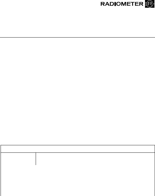
1.Remove the foil from the DosiCapZip and unscrew it (Figs. 1+2).
2.Turn the DosiCapZip upside down and screw it onto the container again (Figs. 3+4).
CAUTIONT: IfT the contents of the DosiCapZip or the container have been spilt by accident, both the container and the DosiCapZip should be discarded to prevent incorrect concentrations in the solution. T
3.Invert the container at least 20 times to dissolve the additive (Fig. 5).
4.Place the container horizontally so that the solution may enter the DosiCapZip and leave it for 3 minutes (Fig. 6).
5.Invert the container again at least 20 times to fully dissolve the additive (Fig. 7).
6.Unscrew the lid from the new solution container.
7.Remove the used solution container by holding it on the sides and pulling.
8.Scan the barcode of the new solution, using the barcode reader.
9.Place the new solution container in position on the analyzer and push it firmly onto the connector as far as possible.
10.For the ABL700 Series analyzers, sw. 3.836: Press Restart to restart the analyzer.
For the ABL700 Series analyzers, sw. 6.00: Press Restart and Accept to restart the analyzer.
©Radiometer Medical ApS, 2700 Brønshøj, Denmark, 2008. All Rights Reserved.
994-702. 200810A.

Cleaning solution with cleaning additive – general information
Texts no longer valid in the manuals
Item |
Code No. |
Type |
|
|
|
Cleaning Solution 175 mL |
944-123 |
S7375 |
T
Use: For cleaning the measuring system of the ABL700 Series analyzers.
Contains: Salts, buffer, anticoagulant, preservatives, surfactants and enzyme. Safety Data Sheet may be obtained from your local distributor.
Storage: At 2-10 °C.
Stability in use: The Cleaning Solution with the Cleaning Additive is stable for 2 months in use.
Analyzer: Perform cleaning every 8th hour.
T CAUTION – Risk of personal injury
DoT not breathe dust (S22). Avoid contact with skin (S24). Irritating to eyes and skin (R36/38). Wear suitable gloves (S37). May cause sensitization by inhalation and skin contact (R42/43). In case of accident or if you feel unwell, seek medical advice immediately (show the label where possible) (S45).
Due to new cleaning solutions, information about Cleaning solution S7370 and Cleaning additive S5370 is no longer valid.
Below is a list of the sections in the manual that must be ignored.
Technical documentation
Instructions to user
ABL700 Series reference manual:
Chapter 7: Solutions and gas mixtures:
S7370 |
Cleaning Solution and |
Text no longer relevant. |
S5370 |
Cleaning additive: |
See instruction about the new Cleaning |
|
|
Solution S7375 above instead. |
|
|
|
Index: |
|
Cleaning Additive references no longer |
|
|
relevant. |
The manuals for the ABL700 Series analyzers will be updated with the above information when reprinted.
This update kit includes a note to the user with the changes and a new date of issue page of the manual. Please place the note to the user in the binder of the ABL700 Series reference manual and replace the date of issue page with the new corresponding page, then discard the old page.

ABL700 Series
Reference
Manual
Contents
1.Introduction
2.Electrodes
3.The Optical System
4.User-defined Corrections
5.Performance Characteristics
6.Parameters
7.Solutions
8.Interfacing Facilities
Index
Date of Issue

SYSTEM PERFORMANCE AND WARRANTY DISCLAIM
Radiometer cannot provide or verify instrument performance characteristics and accept warranty claims or product liability claims if the recommended procedures are not carried out, if accessories other than those recommended by Radiometer are used, or if instrument repairs are not carried out by authorized service representatives.
The instructions given in the Operator’s Manual for the ABL700 Series must be observed in order to ensure proper instrument performance, and to avoid electrical hazards.
TRADEMARKS
ABL™, BMS™, FLM™, CMT™, Deep Picture™, QUALICHECK™ and RADIOMETER™ are trademarks of Radiometer Medical ApS, Denmark.
ABL is registered in the USA.
QUALICHECK is registered in the USA and in some other countries.
COPYRIGHT
The contents of this document may not be reproduced in any form or communicated to any third party without the prior written consent of Radiometer Medical ApS.
While every effort is made to ensure the correctness of the information provided in this document Radiometer Medical ApS assumes no responsibility for errors or omissions which nevertheless may occur.
This document is subjected to change without notice.
♥Radiometer Medical ApS, DK-2700 Brønshøj, Denmark, 2006. All Rights Reserved.
ABL700 Series Reference Manual |
Contents |
||
|
Contents |
|
|
1. |
Introduction .............................................................................................. |
|
1-1 |
|
ABL700 Series Documentation .................................................................. |
|
1-2 |
|
Warnings/Cautions and Notes .................................................................... |
|
1-3 |
2. |
Electrodes .................................................................................................. |
|
2-1 |
|
General Construction .................................................................................. |
|
2-2 |
|
General Measuring Principles..................................................................... |
|
2-3 |
|
Calibration .................................................................................................. |
|
2-7 |
|
Electrode Measuring Time and Updatings ............................................... |
|
2-14 |
|
Reference Electrode.................................................................................. |
|
2-15 |
|
pH Electrode ............................................................................................. |
|
2-16 |
|
pCO2 Electrode ......................................................................................... |
|
2-23 |
|
pO2 Electrode............................................................................................ |
|
2-32 |
|
Electrolyte Electrodes ............................................................................... |
|
2-42 |
|
Metabolite Electrodes ............................................................................... |
|
2-54 |
|
References................................................................................................. |
|
2-64 |
3. |
The Optical System ................................................................................... |
|
3-1 |
|
Measuring Principle.................................................................................... |
|
3-2 |
|
Correcting for Interferences........................................................................ |
|
3-7 |
|
Calibration .................................................................................................. |
|
3-9 |
|
Measurement and Corrections .................................................................. |
|
3-10 |
|
References................................................................................................. |
|
3-13 |
4. |
User-Defined Corrections ......................................................................... |
|
4-1 |
|
General Information.................................................................................... |
|
4-2 |
|
Correction Factors for Oximetry Parameters and Bilirubin........................ |
|
4-4 |
|
Electrolyte and Metabolite Parameters ....................................................... |
|
4-8 |
5. |
Performance Characteristics.................................................................... |
|
5-1 |
|
General Information.................................................................................... |
|
5-2 |
|
Definition of Terms and Test Conditions ................................................... |
|
5-3 |
|
Reference Methods for the ABL700 Series ................................................ |
|
5-8 |
|
ABL735/30/25/20/15/10/05 Performance Test Results - Macromodes.... |
5-10 |
|
|
ABL735/30/25/20/15/10/05 Performance Test Results - Micromodes .... |
5-19 |
|
|
ABL700 Performance Test Results .......................................................... |
|
5-30 |
|
ABL735/30/25/20/15/10/05/00 Expired Air Mode .................................. |
|
5-32 |
|
ABL735/30/25/20/15/10/05/00 Capillary - pH Only Mode ..................... |
|
5-35 |
i
Contents |
ABL700 Series Reference Manual |
|
|
ABL735/30 Performance Test Results - Bilirubin.................................... |
5-36 |
|
Interference Tests...................................................................................... |
5-42 |
|
References................................................................................................. |
5-50 |
6. |
Parameters ................................................................................................. |
6-1 |
|
General Information.................................................................................... |
6-2 |
|
Acid-base Parameters.................................................................................. |
6-6 |
|
Oximetry Parameters .................................................................................. |
6-8 |
|
Oxygen Parameters ..................................................................................... |
6-9 |
|
Bilirubin.................................................................................................... |
6-13 |
|
Electrolyte Parameters .............................................................................. |
6-14 |
|
Metabolite Parameters .............................................................................. |
6-15 |
|
Units and Ranges for Measured Parameters ............................................. |
6-16 |
|
Units and Ranges for Input Parameters .................................................... |
6-19 |
|
Units and Ranges for Derived Parameters ................................................ |
6-20 |
|
List of Equations....................................................................................... |
6-25 |
|
Oxyhemoglobin Dissociation Curve (ODC)............................................. |
6-41 |
|
Conversion of Units.................................................................................. |
6-46 |
|
Default Values .......................................................................................... |
6-48 |
|
Altitude Correction ................................................................................... |
6-49 |
|
References................................................................................................. |
6-50 |
7. |
Solutions and Gas Mixtures ..................................................................... |
7-1 |
|
General Information.................................................................................... |
7-2 |
|
S1720 and S1730 Calibration Solutions ..................................................... |
7-3 |
|
S4970 Rinse Solution ................................................................................. |
7-4 |
|
S7370 Cleaning Solution and S5370 Cleaning Additive............................ |
7-5 |
|
S7770 tHb Calibration Solution.................................................................. |
7-6 |
|
Gas Mixtures (Gas 1 and Gas 2) ................................................................. |
7-7 |
|
Electrolyte Solutions................................................................................... |
7-8 |
|
S5362 Hypochlorite Solution ..................................................................... |
7-9 |
|
Certificates of Traceability ....................................................................... |
7-10 |
8. |
Interfacing Facilities ................................................................................. |
8-1 |
|
Connecting a Mouse ................................................................................... |
8-2 |
|
Connecting an Alphanumeric Keyboard..................................................... |
8-3 |
|
Connecting the Bar Code Reader................................................................ |
8-4 |
|
Connecting a Network ................................................................................ |
8-6 |
Index |
|
|
Date of Issue |
|
|
ii
ABL700 Series Reference Manual |
1. Introduction |
|
|
1. Introduction |
|
Overview |
This section gives an introduction to the documentation that accompanies your |
|
|
ABL700 Series analyzer. It describes how this particular manual is organized and |
|
|
explains the different notices that appear in it. |
|
Contents |
This chapter contains the following topics. |
|
|
ABL700 Series Documentation ....................................................................... |
1-2 |
|
Warnings/Cautions and Notes.......................................................................... |
1-3 |
1-1
1. Introduction |
ABL700 Series Reference Manual |
ABL700 Series Documentation
ABL700 Series |
The documentation that accompanies the ABL700 Series analyzers covers the |
Analyzers |
series in general - each possible electrode combination is not considered |
|
individually. |
Documentation The table below describes the documentation that comes with each analyzer.
Documentation |
Description |
|
|
The Operator’s |
Contains all the information required for everyday |
Manual |
operation of the analyzer. |
|
Describes the functions of the analyzer and how to set it up |
|
according to customer needs and requirements. |
|
Explains error messages and gives troubleshooting |
|
procedures. |
|
Contains ordering information |
|
|
The Reference |
Gives detailed information about the operating principles |
Manual |
of the analyzer. |
|
Describes the measuring and calibrating principles. |
|
Lists all the parameters. |
|
Gives the equations from which the derived parameters are |
|
calculated. |
|
Gives information about how the performance of the |
|
analyzer is tested. |
|
|
On-line Help |
Summarizes the information found in the Operator’s |
|
Manual. |
|
Gives hands-on help at the analyzer. |
|
|
Design of |
Depending on the set up of your analyzer, the entire Reference Manual may not be |
Manual |
applicable to it. However the manual is designed in such a way that it is easy to |
|
disregard or remove the sections that are not relevant to your instrument. |
1-2
ABL700 Series Reference Manual |
1. Introduction |
Warnings/Cautions and Notes
Definitions |
The following table indicates the type of information given in warnings, cautions, |
|
|
and notes: |
|
|
|
|
|
Notice |
Definition |
|
WARNING |
Warnings alert users to potentially serious outcomes to |
|
|
themselves or to the patient (such as death, injury, or serious |
|
|
adverse events). |
|
PRECAUTION |
Precautions alert users to exercise the special care necessary |
|
|
for safe and effective use of the device. They may include |
|
|
actions to be taken to avoid effects situations on patients or |
|
|
users that may not be potentially life threatening or result in |
|
|
serious injury , but about which the user should be aware. |
|
|
Precautions may also alert the user to adverse effects on the |
|
|
device caused by use or misuse, and the care required to |
|
|
avoid such effects. |
|
NOTE |
Notes give practical information. |
List of |
All WARNING/CAUTION notices that appear in this manual, are listed below. |
|
WARNING/ |
|
|
CAUTION |
• S5370 Cleaning Additive: May cause sensitization by inhalation and skin |
|
Notices |
contact). Do not breathe dust. Avoid contact with skin. Wear suitable gloves. |
|
|
In case of accident or if you feel unwell, seek medical advice immediately |
|
|
(show the label where possible). |
|
•Gas Mixtures: Not for drug use. High pressure gas. Do not puncture. Do not store near heat or open flame - exposure to temperatures above 52 oC
(125 oF) may cause contents to vent or cause bursting.
Not for inhalation. Avoid breathing gas - mixtures containing carbon dioxide can increase respiration and heart rate. Gas mixtures containing less than
19.5 % oxygen can cause rapid suffocation.
Store with adequate ventilation. Avoid contact with oil and grease. Only use with equipment rated for cylinder pressure.
Use in accordance with Safety Data Sheet.
1-3
|
2. Electrodes |
|
Introduction |
This chapter describes the construction, measuring principle and calibration |
|
|
process for each of the electrodes in the ABL700 Series analyzers. |
|
|
General sections covering the background theory used for measurements and |
|
|
calibrations are also presented here. |
|
Contents |
This chapter contains the following topics. |
|
|
General Construction ....................................................................................... |
2-2 |
|
General Measuring Principles .......................................................................... |
2-3 |
|
Calibration........................................................................................................ |
2-7 |
|
Electrode Measuring Time and Updatings....................................................... |
2-14 |
|
Reference Electrode ......................................................................................... |
2-15 |
|
pH Electrode .................................................................................................... |
2-16 |
|
pCO2 Electrode................................................................................................. |
2-24 |
|
pO2 Electrode ................................................................................................... |
2-33 |
|
Electrolyte Electrodes ...................................................................................... |
2-43 |
|
Metabolite Electrodes....................................................................................... |
2-55 |
|
References........................................................................................................ |
2-65 |
2. Electrodes |
ABL700 Series Reference Manual |
General Construction
An Electrode In this manual and other Radiometer literature, the term electrode refers to the whole sensor unit, i.e. both the electrode and the electrode jacket. Radiometer electrodes are cordless, thereby limiting the level of noise picked up during the measuring process. The electrical signals from the electrodes are amplified by preamplifiers placed in each module.
A generalized diagram of a Radiometer electrode is given below.
Electrical contact
Electrolyte solution |
|
|
|
|
|
|
|
|
|
|
Color-coded ring |
|
|
|
|
|
|
|
|
|
|
||
|
|
|
|
|
|
|
|
|
|
||
|
|
|
|
|
|
|
|
||||
|
|
|
|
|
|
|
|
|
|
Electrode jacket |
|
|
|
|
|
|
|
|
|
|
|||
|
|
|
|
|
|
|
|
|
|
|
|
Membrane
The main electrode parts are described below.
Part |
Description |
Electrical contact |
Provides electrical contact between the electrode and the |
|
analyzer. |
Color-coded ring |
Marks each electrode for easy recognition. |
Electrode jacket |
Holds the electrolyte solution and membrane, and protects |
|
the electrode. |
Membrane |
A thin sheet-like material to separate the sample from the |
|
electrode, that differentiates between the substances |
|
allowed to pass through it towards the electrode. |
Electrolyte |
A conducting solution to provide an electric contact |
solution |
between the electrode and the sample (also known as a |
|
salt-bridge solution). |
More specific descriptions of the electrodes are found under the appropriate electrode titles in this chapter.
2-2
ABL700 Series Reference Manual |
2. Electrodes |
General Measuring Principles
Introduction There are two different measuring principles employed for electrodes in the ABL700 Series.
•Potentiometry: The potential of an electrode chain is recorded using a voltmeter, and related to the concentration of the sample (the Nernst equation).
•Amperometry: The magnitude of an electrical current flowing through an electrode chain, which is in turn proportional to the concentration of the substance being oxidized or reduced at an electrode in the chain.
These two measuring principles are described in detail on the following pages.
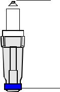
Potentiometric |
An electrode chain describes an electrical circuit consisting of a sample, electrode, |
||
Method |
reference electrode, voltmeter, membranes, and electrolyte solutions. |
||
|
|
|
Voltmeter |
V
Reference |
Electrolyte |
Sample |
Electrolyte |
Electrode |
|
electrode |
solution |
solution |
|||
|
|
Membrane |
|
Membrane |
|
Every element in the electrode chain contributes a voltage to the total potential drop through the chain. Thus:
•When immersed in the appropriate electrolyte solution, both electrodes have separate potentials.
•The membrane junctions between the sample and electrolyte solutions also have separate potentials.
The complete electrode chain potential therefore, is the sum of these separate potentials and is the quantity measured by the voltmeter.
Etotal = Esample – ERef
where the final unknown potential (Esample) can be calculated knowing the total electrode chain potential (Etotal) and the reference potential (ERef that is constant between two subsequent calibrations).
Continued on next page
2-3

2. Electrodes |
ABL700 Series Reference Manual |
General Measuring Principles, Continued
Potentiometric Method
(continued)
Having measured the unknown potential (Esample), the Nernst equation is then applied to determine the activity (ax) of the species under study:
Esample = E0 + 2.3RnFT log ax
where:
E0 |
= standard electrode potential |
R= gas constant (8.3143 JK−1mol−1)
T |
= |
absolute temperature (310 K (37 oC )) |
n |
= |
charge on the ion |
F= Faraday constant (96487 C mol−1)
ax |
= activity ofx |
The Nernst equation is rearranged to express the activity as a function of the
potential Esample. Having measured Esample the activity can be calculated since all other quantities are already known. Finally the analyzer converts activity to
concentration.
Strictly speaking, in potentiometry the potential of an electrode chain or the magnitude of current flowing through an electrical chain is related to the activity of a substance, and not its concentration.
Activity expresses the ‘effective concentration’ of a species, taking non-ideality of the medium into account.
Activity and concentration are related by the following equation:
ax = γ cx
where:
ax |
= the activity of the species x |
γ= the activity coefficient of species x under the measurement conditions (for ideal systems γ = 1)
cx |
= the concentration of species x (mmol/L) |
NOTE: To be exact, activity is related to the molality of species x, i.e., the number of mmoles per kg of solvent. However molality is converted to concentration (molarity).
ABL700 Series analyzers automatically convert activities into concentrations [1]. The term concentration is therefore used in explanations of the measuring principles for each of the electrodes further on in this chapter.
The potentiometric measuring principle is applied in the pH, pCO2, and electrolyte electrodes. It is slightly different for the pCO2 electrode, however, since the Nernst equation is not directly applied.
Continued on next page
2-4
ABL700 Series Reference Manual |
2. Electrodes |
General Measuring Principles, Continued
Amperometric The electrode chain in amperometric measurements consists of the sample, the two Method electrodes (anode and cathode), an amperemeter, a voltage source, the membranes,
and the electrolyte solutions.
Amperemeter
Applied voltage
|
Anode |
|
|
|
|
|
|
|
|
|
|
|
|
|
|
|
|
|
|
|
|
|
|
|
|
|
|
|
|
|
|
|
Cathode |
|
|
|
|
|
|
|
|
|
|
|
|
|
|
|
|
|
|
|
|
|
|
|
|
|
|
|
|
|
|
|
|
||
|
|
|
|
|
|
|
|
|
|
|
|
|
|
|
|
|
|
|
|
|
|
|
|
|
|
|
|
|
|
|
|
||
|
|
|
|
|
|
|
|
|
|
|
|
|
|
|
|
|
|
|
|
|
|
|
|
|
|
|
|
|
|
|
|
||
|
|
|
|
|
|
|
|
|
|
|
|
|
|
|
|
|
|
|
|
|
|
|
|
|
|
|
|
|
|
|
|
||
Electrolyte solution |
|
|
|
|
|
|
|
|
|
|
|
|
|
|
|
|
|
|
|
|
|
|
|
|
|
|
|
|
|
|
|
Membrane |
|
|
|
|
|
|
|
|
|
|
|
|
|
|
|
|
|
|
|
|
|
|
|
|
|
|
|
|
|
|
|
|
|||
|
|
|
|
|
|
|
|
|
|
|
|
|
|
|
|
|
|
|
|
|
|
|
|
|
|
|
|
|
|
|
|||
|
|
|
|
|
|
|
|
|
|
|
|
|
|
|
|
|
|
|
|
|
|
|
|
|
|
|
|
|
|
|
|||
|
|
|
|
|
|
|
|
|
|
|
|
|
|
|
|
|
|
|
|
|
|
|
|
|
|
|
|
|
|
|
|||
|
|
|
|
|
|
|
|
|
|
|
|
|
|
|
|
|
|
|
|
|
|
|
|
|
|
|
|
|
|
|
|||
|
|
|
|
|
|
|
|
|
|
|
|
|
|
|
|
|
|
|
|
|
|
|
|
|
|
|
|
|
|
|
|||
|
|
|
|
|
|
|
|
|
|
|
|
|
|
|
|
|
|
|
|
|
|
|
|
|
|
|
|
|
|
|
|
|
|
|
|
|
|
|
|
|
|
|
|
|
|
|
|
|
|
|
|
|
|
|
|
|
|
|
|
|
|
|
|
|
|
|
|
|
|
|
|
|
|
|
|
|
|
|
|
|
|
|
|
|
|
|
|
|
|
|
|
|
|
|
|
|
|
|
|
|
|
|
|
|
|
|
|
|
|
|
|
|
|
|
|
|
|
|
|
|
|
|
|
|
|
|
|
|
|
|
|
|
|
|
|
|
|
|
|
|
|
|
|
|
|
|
|
|
|
|
Sample |
|
|
|
|
|
|
|
|
|
|||||||||
Part |
|
|
|
|
|
|
|
|
|
|
|
|
|
|
|
|
|
|
|
|
|
|
|
|
Function |
||||||||
|
|
|
|
|
|
||||||||||||||||||||||||||||
Cathode |
Negative electrode where a reduction reaction occurs and |
||||||||||||||||||||||||||||||||
|
electrons are consumed. |
|
|
|
|
|
|
|
|
|
|||||||||||||||||||||||
Anode |
Positive electrode where an oxidation reaction occurs and |
||||||||||||||||||||||||||||||||
|
electrons are released. |
|
|
|
|
|
|
|
|
|
|||||||||||||||||||||||
Electrolyte |
Provides electrical contact between the anode and cathode. |
||||||||||||||||||||||||||||||||
solution |
|
|
|
|
|
|
|
|
|
|
|
|
|
|
|
|
|
|
|
|
|
|
|
|
|
|
|
|
|
|
|
|
|
Membrane |
Allows the appropriate molecules to pass through from the |
||||||||||||||||||||||||||||||||
|
sample. |
|
|
|
|
|
|
|
|
|
|||||||||||||||||||||||
Sample |
Contacts the membrane. |
|
|
|
|
|
|
|
|
|
|||||||||||||||||||||||
Applied voltage |
Applies the necessary potential for the reduction or oxidation |
||||||||||||||||||||||||||||||||
|
reaction under study. |
|
|
|
|
|
|
|
|
|
|||||||||||||||||||||||
Amperemeter |
Measures the current flowing through the circuit. |
||||||||||||||||||||||||||||||||
To simplify the description of the measuring process in an amperometric electrode, we make the following assumptions:
•there is a species A in the sample which is reduced at the cathode to A−.
•there is a species X in the electrolyte which is oxidized at the anode to X+.
Continued on next page
2-5
2. Electrodes |
ABL700 Series Reference Manual |
General Measuring Principles, Continued
Amperometric Method
(continued)
The membrane is selective to the species A, allowing no other species but it to pass through from the sample into the electrolyte solution.
As an appropriate potential is applied across the electrodes, the species A is reduced at the cathode according to the following reaction:
A + e− → A−
The reduction of A produces a flow of electrons, i.e. an electrical current.
To complete the electrical circuit an oxidation reaction where electrons are released is necessary. Therefore species X is oxidized according to the following reaction:
X → X+ + e−
The magnitude of the current flowing through the circuit is proportional to the concentration of the species being reduced, in this case species A. The analyzer thereby automatically calculates the concentration of A in the sample.
The amperometric measuring principle is applied in the pO2, glucose, and lactate electrodes.
2-6
ABL700 Series Reference Manual |
2. Electrodes |
Calibration
Actual Electrode |
The electrodes are active elements and must be calibrated regularly as the signals |
||
Condition |
from the electrodes change with, e.g. age or deposits on the membrane. |
||
|
Calibration relates the electrode signals during the calibration sequence to the |
||
|
values of the calibrating solutions and must be performed at regular intervals so |
||
|
that the accuracy can be constantly refined after inevitable minor changes in the |
||
|
electrodes’ behavior. |
||
|
Actual electrode condition is described by status/zero point and sensitivity and |
||
|
compared with theoretical conditions for an "ideal" electrode. In addition to status |
||
|
and sensitivity, an electrode condition is described by drift. |
||
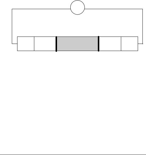
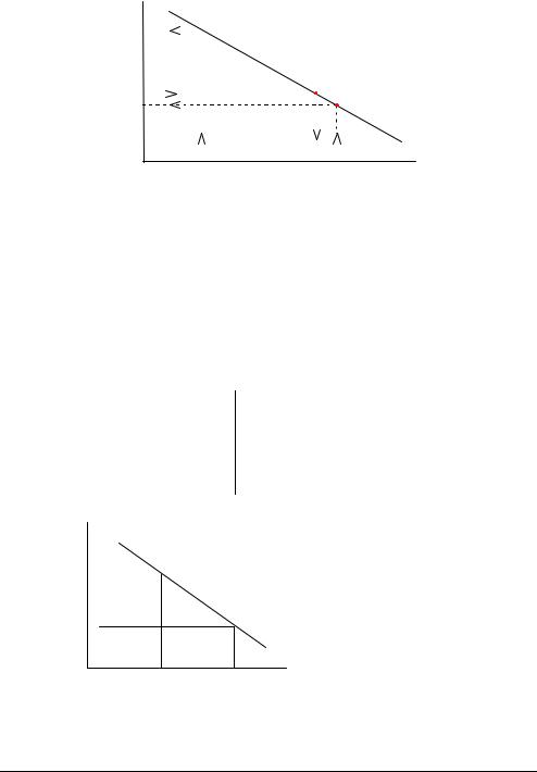
Calibration Line |
The calibration line expresses the relationship between the potential (or current) |
||
|
measured at an electrode, and the concentration of the species specific to the |
||
|
electrode. The calibration line forms the basis of the scale used by the analyzer to |
||
|
convert electrode chain potentials to concentrations. Each electrode has a different |
||
|
calibration line. |
||
|
The pH electrode is used as an example to illustrate how this line is derived from |
||
|
two calibration solutions of known pH. |
||
|
• Cal 1 solution has a pH of 7.398 that gives potential reading of −100 mV. |
||
|
• Cal 2 solution has a pH of 6.802 that gives a potential reading of −64 mV. |
||
|
These two values are plotted on a graph. |
||
|
The relationship between potential and pH is linear so a line can be drawn between |
||
|
the two points, as shown below: |
||
|
Measured |
||
|
potential |
||
|
(mV) −64 |
||
|
|
|
Calibration line |
|
|
|
|
|
−97 |
||
|
−100 |
||
6.802 |
7.346 7.398 |
pH |
|
||
pH of Cal 2 sol. |
pH of sample pH of Cal 1 sol. |
|
The calibration line now forms the scale used to convert the potential measured at the pH electrode during sample analysis to an actual pH value.
Continued on next page
2-7
2. Electrodes |
ABL700 Series Reference Manual |
Calibration, Continued
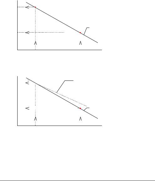
Calibration Line A blood sample gives a potential reading of -97 mV at the pH electrode. Reading (continued) off from the calibration line shown below, this potential corresponds to a pH of
7.346.
Measured potential (mV) −64


−97 |
|
|
Calibration line |
|
|
||
|
|
|
|
−100 |
|
|
|
6.802 |
7.346 7.398 |
pH |
|
|
|||
pH of Cal 2 sol. |
pH of sample pH of Cal 1 sol. |
||
The calibration line is updated at every calibration. Drift describes the variation in the calibration line between consecutive calibrations.
Theoretical The theoretical calibration line is the relationship between potential and Calibration Line concentration in a potentiometric measurement, or the relationship between current
and concentration in an amperemetric measurement.
In the ABL700 Series the theoretical calibration line for pH is defined by the following two points:
pH |
Electrode potential |
|
(vs. Ref. potential) |
|
|
6.800 |
−75.5 mV |
7.400 |
−112.4 mV |
Measured potential (mV)
−75.5 
−112.4 
6.8 |
7.4 |
pH |
|
The position and slope of the calibration line compared to the theoretical calibration line are described by the status and sensitivity respectively.
Continued on next page
2-8
ABL700 Series Reference Manual |
2. Electrodes |
Calibration, Continued
Sensitivity |
Electrode sensitivity expresses how a real electrode measures compared with the |
|
specified values of the calibration material; it illustrates the slope of the calibration line |
|
derived from a 2-point calibration as a percentage (or fraction) of the slope of the |
|
theoretical calibration line, as determined by the Nernst equation of the ion in question. |
|
Calculating the sensitivity is a way of monitoring the deviation of the electrode |
|
sensitivity from the theoretical value. |
|
Calculation of the sensitivity is shown, using the pH electrode as an example. |
|
A theoretical calibration line for the pH electrode with a slope of −61.5 mV/pH is |
|
drawn: |
|
Measured |
|
potential |
|
(mV) −75.5 |
|
Theoretical calibration line |
|
−112.4 |
pH
6.8 |
7.4 |
The calibration line from a 2-point calibration is superimposed on the same graph:
Measured potential (mV) −75.5


−112.4


6.8
2-point calibration line Slope = −58.4 mV/pH Sensitivity = 95 %
Theoretical calibration line Slope= −61.5 mV/pH Sensitivity = 100 %
 pH 7.4
The sensitivity of the electrode is calculated as the ratio between the slope of the 2- point calibration line and that of the theoretical line, expressed as a percentage or fraction.
If the theoretical calibration line is assumed to have a sensitivity of 100 %, the 2- point calibration line shown in the example will have a sensitivity of approximately 95 %.
Continued on next page
2-9
2. Electrodes |
ABL700 Series Reference Manual |
Calibration, Continued
Sensitivity
(continued)
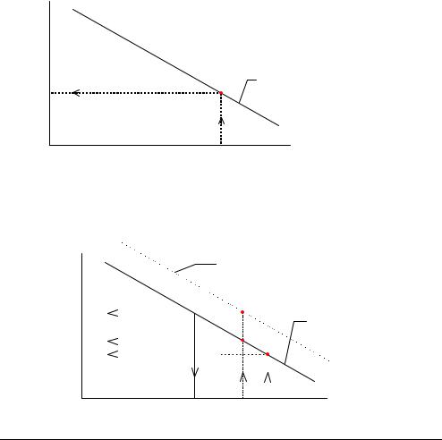
Status
The sensitivity limits for the calibration are set for each electrode. If the sensitivity of any electrode falls outside the allowed limits, the message Calibration Sensitivity out of range appears in the Calibration Messages, with the particular electrode specified.
The electrode status is a measure of zero point of a complete electrode chain. Status of a real electrode reflects deviations from the conditions of a theoretical electrode, and define the position of the calibration line.
Calculating the status value of an electrode is a way of monitoring the position of the calibration line despite the fact that only a 1-point calibration has been carried out. The calculation of the status is shown, using the pH electrode as an example.
A calibration line with the same slope as the theoretical calibration line (−61.5 mV/pH) is drawn through this point. This theoretical calibration line is used since no 2-point calibration is performed which would otherwise give an actual calibration line.
Measured potential (mV)
ECal 1
Theoretical calibration line with a slope = −61.5 mV/pH drawn through the point from a 1-point calibration.
pH
pHCal 1
A pH of 7.400, the nominal pH of Calibration Solution 1 (pHCal 1 nom) is chosen. Its corresponding potential (ECal 1 nom) is read off the theoretical calibration line that
was drawn through the 1-point calibration point.
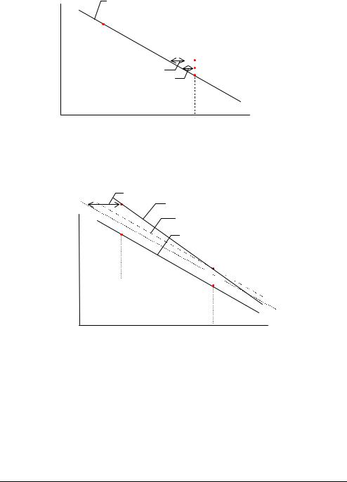
Measured potential (mV)
ECal 1 nom(theo)


E=−112.4 mV
ECal 1 nom


ECal 1 


Theoretical calibration line for the theoretical pH electrode with known potential of −112.4 mV at a pH = 7.400.
∆pH |
Theoretical calibration |
|
line drawn through the 1- |
∆E |
point calibration point. |
pH
pHStatus pHCal 1 nom pHCal 1
(7.400)
Continued on next page
2-10

ABL700 Series Reference Manual |
2. Electrodes |
Calibration, Continued
Status
(continued)
Calibration
Materials
A line from pHCal 1 nom is extrapolated up to the theoretical calibration line, and the corresponding potential (ECal 1 nom(theo)) read off the theoretical calibration line.
The difference between ECal 1 nom and ECal 1 nom(theo) which corresponds to ∆E on the graph, represents the potential that should theoretically be obtained for a solution
with pH = 7.400. This potential difference (∆E) thus describes the deviation of the actual pH reference electrode system from a theoretical electrode system.
Similarly ∆pH describes the deviation in pH values that would be produced between measurements with an actual electrode system and measurements with a theoretical electrode system.
The status of the pH electrode, pH(Status), is then calculated as:
pH(Status) = 7.4 + |
ECal 1 nom − ECal 1 nom(theo) |
|
61.5 |
||
|
The status limits of the calibration are set for each electrode. If the status for any electrode falls outside the allowed limits, the message Calibration status out of limits appears in the Calibration Messages, with the particular electrode specified.
The following calibration materials are used:
Calibration Material |
Used for... |
|
|
Calibration Solutions 1 and 2: the exact composition of |
Calibration of the pH, |
the calibration solutions is given in the bar code on the |
and electrolyte |
bottle label, which can be read into the analyzer using the |
electrodes |
bar code reader, or entered manually via the keyboard. |
|
|
|
Calibration Solution 1: |
Calibration of the |
|
metabolite electrodes |
|
and optical system |
Gas 1 and Gas 2: each gas has a precise composition |
Calibration of the |
essential for determining the accuracy of the analyzer in |
pCO2 and pO2 |
each pCO2 and pO2 measurement. |
electrodes |
tHb Calibration Solution: |
Calibration of the |
|
optical system |
|
|
The Chemical Reference Laboratory at Radiometer is responsible for the accuracy of the calibrating solutions and gases.
Traceability certificates for individual solutions are presented in Chapter 7 of this manual.
Continued on next page
2-11
2. Electrodes |
ABL700 Series Reference Manual |
Calibration, Continued
Drift |
Drift is defined as the difference measured by the electrodes during last and |
|||
|
previous calibrations, and is a measure of the electrode stability. |
|||
|
Drift 1 is obtained on Calibration Solution 1 and/or Gas 1 and is calculated as |
|||
|
follows, using the pH electrode as an example: |
|
|
|
|
Measured |
Calibration line from last |
|
|
|
2-point calibration |
|
|
|
|
potential |
|
|
|
|
|
|
|
|
|
(mV) |
|
|
|
|
|
|
|
2nd 1-point calibration |
|
|
|
|
|
|
|
2nd Drift 1 value |
|
1st 1-point calibration |
|
|
|
||
|
|
1st Drift 1 value |
|
2-point calibration |
|
|
|
||
|
pH |
pH |
pH |
Calibration Solution 2 |
Calibration Solution 1 |
Drift 2 is obtained after 2-point calibration. The pH electrode is used as an example and the calibration schedule is set so that each 2-point calibration is separated by two 1-point calibrations.
Measured potential (mV)
Drift 2
Calibration line from 2nd 2-point calibration
Slope of 1st 2-point calibration line
Calibration line from 1st 2-point calibration


 2nd 1-point calibration
 1st 1-point calibration
pH
pH |
pH |
Calibration Solution 2 |
Calibration Solution 1 |
Drift tolerances express the extent to which drift values for an electrode can fluctuate before the electrode is deemed unstable and thus incapable of providing reliable calibrations.
The drift tolerances for each electrode are set in the analyzer’s Setup programs. Radiometer recommends the use of the default drift tolerances, as too narrow drift tolerances will cause electrode drift errors even for normal electrode fluctuations. If the drift tolerances are too wide, significant measurement errors will result without warning.
Continued on next page
2-12
ABL700 Series Reference Manual |
2. Electrodes |
Calibration, Continued
Drift (continued) If the drift values for any electrode fall outside the drift tolerances, the message Calibration drift out of range appears in the Calibration Messages, with the particular electrode specified.
No drift values are reported for startup calibrations as there are no previous calibrations available for comparison.
2-13
2. Electrodes |
ABL700 Series Reference Manual |
Electrode Measuring Time and Updatings
Measuring Time In the ABL700 Series analyzers the measuring time of the electrode is independent of the electrode type. Electrode signals are registered at 0.982 second intervals during both calibrations and measurements. The registration of each electrode signal begins after the samples, calibration solutions, and calibration gases are in position in the measuring modules.
The duration of each calibration is predetermined, as is the number of updatings of the electrodes’ signals.
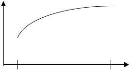
Updatings |
In general, the updatings from an electrode response are numbered from 1 to upd |
|
last, where updating number 1 is the first updating and upd last is the last. The |
|
diagram below schematically illustrates the electrode response that is calculated on |
|
uncorrected electrode updating values in the ABL700 Series. |
|
Signal |
Updatings
Upd 1 |
Upd last |
2-14
Loading...