

Page 1
ION450
User’s Guide
D21M075
Contents 1
Page 2

D21M075 • Printed by Radiometer Analytical SAS • 2004-03B
2 Contents
Page 3

ContentsContents
Contents
ContentsContents
1. Introduction ........................................................................5
Read me! ........................................................................................... 5
2. Getting started....................................................................11
Keyboard............................................................................................ 11
Basic principles ................................................................................. 12
Main window ...................................................................................... 14
Electrodes window ............................................................................. 15
Cell window ........................................................................................ 17
System configuration ......................................................................... 18
3. Programming guidelines ...................................................27
Create an electrode ............................................................................ 28
Edit electrode screen ......................................................................... 30
Programming electrode parameters.................................................... 33
Create a method ................................................................................ 34
Edit method screen............................................................................ 35
Programming method parameters ...................................................... 37
4. Running analyses...............................................................39
Run electrode calibration.................................................................... 40
Run method ....................................................................................... 40
Run direct measurement .................................................................... 40
5. Viewing data........................................................................41
Sample results................................................................................... 42
Electrode calibration results ............................................................... 43
6. Printing data .......................................................................45
Manual printouts ................................................................................ 46
Automatic printouts ............................................................................ 48
Contents 3
Page 4

7. Connection of peripherals.................................................49
8. General information ...........................................................51
Cleaning............................................................................................. 51
T ransporting the instrument................................................................ 51
Servicing............................................................................................ 51
4 Contents
Page 5

1. Intr1. Intr
1. Intr
1. Intr1. Intr
Read me!Read me!
Read me!
Read me!Read me!
The interface of the Ion Analyser has been specially designed to clearly
guide you through every step of the programming and running of the
analyses, whether you are a supervisor or a routine user.
An important part of this interface is to check and control the presence of
different elements necessary to run the defined application.
Working in Supervisor modeWorking in Supervisor mode
Working in Supervisor mode
Working in Supervisor modeWorking in Supervisor mode
When programming in “SUPERVISOR” mode, it is recommended to
work in stages. These stages
below:
To program a methodTo program a method
To program a method
To program a methodTo program a method
1. Define your electrode(s)
Identify electrodes (including temperature sensors) to be used for the
analysis.
Electrodes can be created from the following lists, Catalogue, Other or
Copy from. When creating the electrode, define if electrode calibration is
required (or not), if yes specify the “periodicity” of the calibrations and the
standards to be used. Refer to chapter 3.
oductionoduction
oduction
oductionoduction
should
be carried out in the order described
2. Create a new method or Edit a pre-programmed one
Create the measurement method to be used for the analyses. Enter the
parameters required to calculate the results, refer to chapter 3.
When you have finished programming, select the method or preprogrammed application, refer to Short-Form Reminder no. 2.
If a sample changer is to be used, define the sample changer in the
Configuration menu before selecting Working mode = SAC
sequence in the main window.
Introduction 5
Page 6
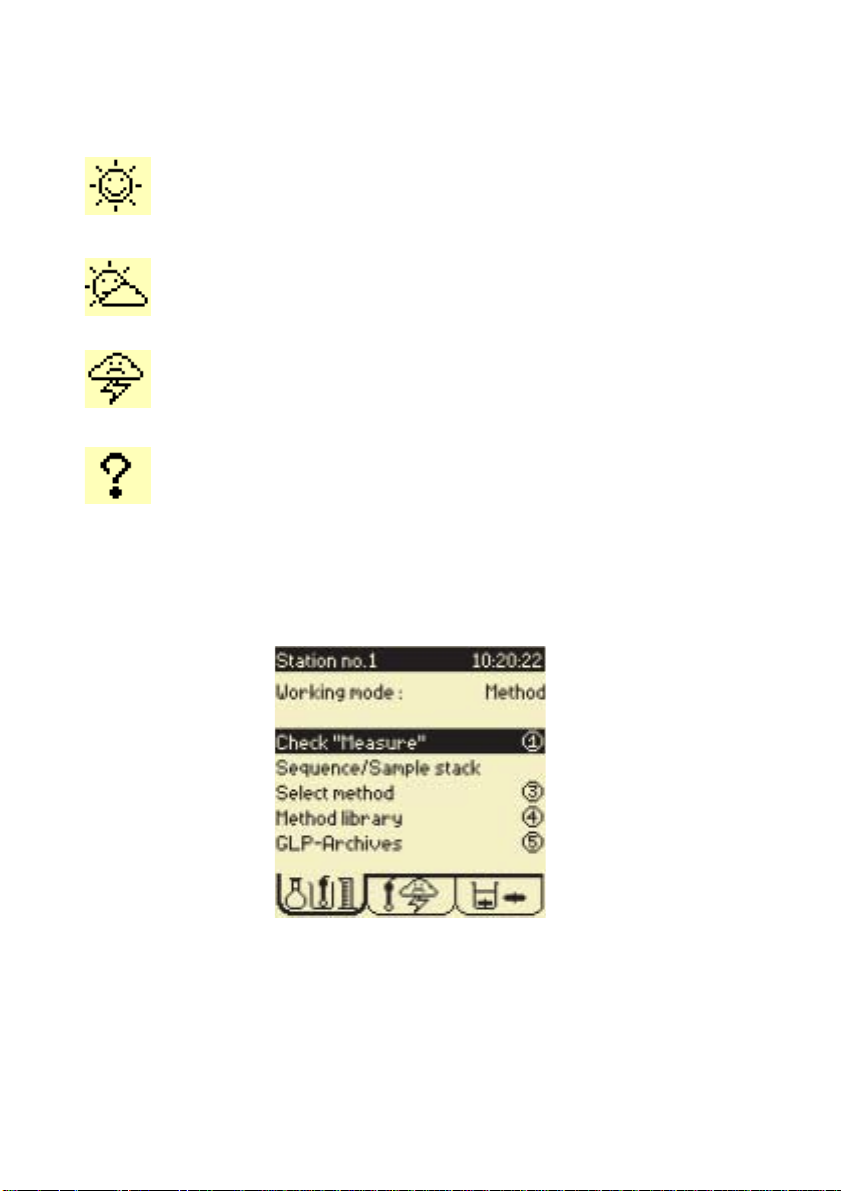
3. Check icons
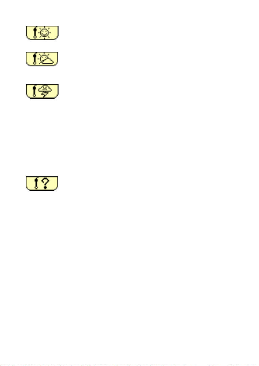
The following icons indicate the exact state of your working system.
Sunny icon:
Everything is OK. Run the method or sequence.
A sunny icon is required to run the method
Cloudy icon:
Action required within 12 or 24 hours. For example an
electrode calibration.
Stormy icon:
Electrode calibration date elapsed or electrodes not
installed.
Question mark:
It is a programming error, electrodes are not defined in the
selected method. Revise the method programming.
Refer to the Electrode window.
.
When a Cloudy/Stormy/Question mark icon appears, Press 1
“Check”. The Ion Analyser will automatically guide you through the
operations necessary to solve the errors encountered
.
4. Running methods
To run a method or sequence, refer to chapter 4.
6 Chapter 1
Page 7
Working in Routine modeWorking in Routine mode
Working in Routine mode
Working in Routine modeWorking in Routine mode
In “ROUTINE” mode you are guided at every step, thanks to the cleartext messages and the icon present on the large graphic display.
Access methodsAccess methods
Access methods
Access methodsAccess methods
A Routine operator has access to all the displays for
Running methodsRunning methods
Running methods
Running methodsRunning methods
When working in “ROUTINE” mode, it is necessary to install your
measurement system according to the selected method or sequence,
prior to running a method or sequence.
1. Select the method or sequence
Refer to chapter 4.
checking
purposes.
Introduction 7
Page 8
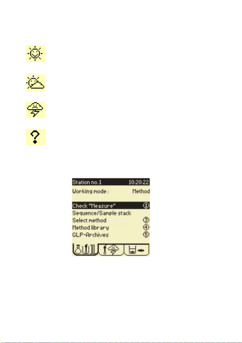
2. Check icons
The following icons indicate the exact state of your working system.
Sunny icon:
Everything is OK. Run the method or sequence.
A sunny icon is required to run the method
Cloudy icon:
Action required within 12 or 24 hours. For example an
electrode calibration.
Stormy icon:
Electrode calibration date elapsed or electrodes not
installed.
Question mark:
It is a programming error, electrodes are not defined in the
selected method. Revise the method programming.
Refer to the Electrode window.
.
When a Cloudy/Stormy/Question mark icon appears, press 1 to run
the “Check” command.
Depending on the icon displayed, the Ion Analyser will
automatically guide you through the steps necessary to run the
analysis, see following page.
8 Chapter 1
Page 9

a. Connect/install the electrode(s)
Connect/install electrodes and temperature sensors, Refer to
chapter 3.
b. Calibrate electrode(s)
Run the electrode calibration, refer to chapter 4 and Short Form
Reminder no. 3.
d. Run the method or the sequence, when a Sunny icon is
displayed,
Refer to chapter 4 and Short Form Reminder no. 4 and 5.
Introduction 9
Page 10

10 Chapter 1
Page 11
2. Getting star2. Getting star
2. Getting star
2. Getting star2. Getting star
KeyboardKeyboard
Keyboard
KeyboardKeyboard
tedted
ted
tedted
1
2
3
4
67
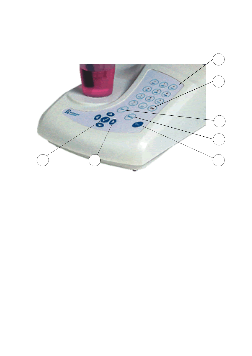
1. Alphanumeric keypad to enter data and parameters on the same
principle as mobile telephones. These keys can also be used for
quick access to the different menus; refer to the display on the
following page.
2. Del: deletes the character on which the cursor is positioned.
3. Esc: returns to the previous screen. During analysis, this key allows
you to enter the method, electrode and cell menu.
4. Print: prints the data concerning the screen displayed.
5. Stop: stops an analysis. Press this key for 3 seconds in the Main
window to gain access to the setup parameters.
6. RIGHT, LEFT, UP, DOWN arrow keys are used to move to different
options within the menus.
7. ✓: confirms a data entry, a message or a function asked for by the
user.
5
Getting started 11
Page 12
Basic principlesBasic principles
Basic principles
Basic principlesBasic principles
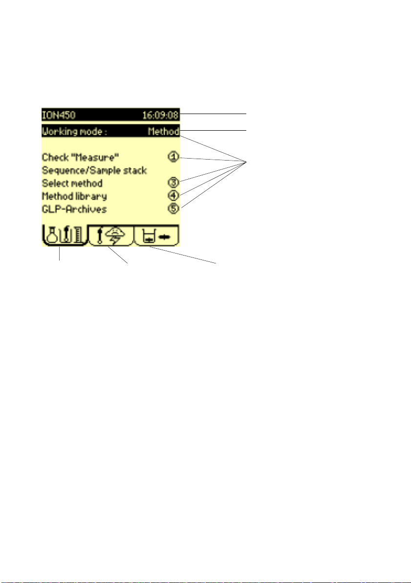
When the instrument is switched on, the Main window is displayed.
When the instrument is switched on for the first time the screen will be
as follows:
Title bar
Selected line
Menu options.
Press the
corresponding number
for quick access to the
different menus. For
example, press 4 to
enter the Method library
Method tab
If required, you can adjust the contrast of the display by:
• pressing 0 to increase the brightness,
• pressing 7 to decrease the brightness.
The title bar in the menu indicates the instrument name and the actual
time. You will be shown how to personalise the name and adjust the time
further on in the manual.
The RIGHT and LEFT arrow keys allow you to move from one tab to the
other and enter the Electrode and Cell menus.
• Work your way through the 3 tabs, then back to the Main window.
The UP and DOWN keys allow you to select a line. To enter an option,
select the line, and press ✓. You can also press the corresponding
numerical key.
Electrode tab Cell tab
12 Chapter 2
Page 13

1. Press 4 or select the line Method library and press ✓ to enter the
Method library screen. Press Esc to return to the Main window.
2. Select the line Working mode and press ✓. The following
options are available:
Method: to run a single method.
Sequence: to create or run a sequence of methods. Beakers are
manually changed between two method runs.
SAC Method: to run a single method to be performed using a
sample changer.
SAC Sequence: to create or run a sequence of methods to be
performed using a sample changer.
Note: the working mode selected will have no effect on the type of
method you wish to create.
Do not forget to define the sample changer in the Configuration
menu before selecting SAC Method or SAC Sequence.
3 Press ✓ to confirm your selection.
Getting started 13
Page 14
Main windowMain window
Main window
Main windowMain window
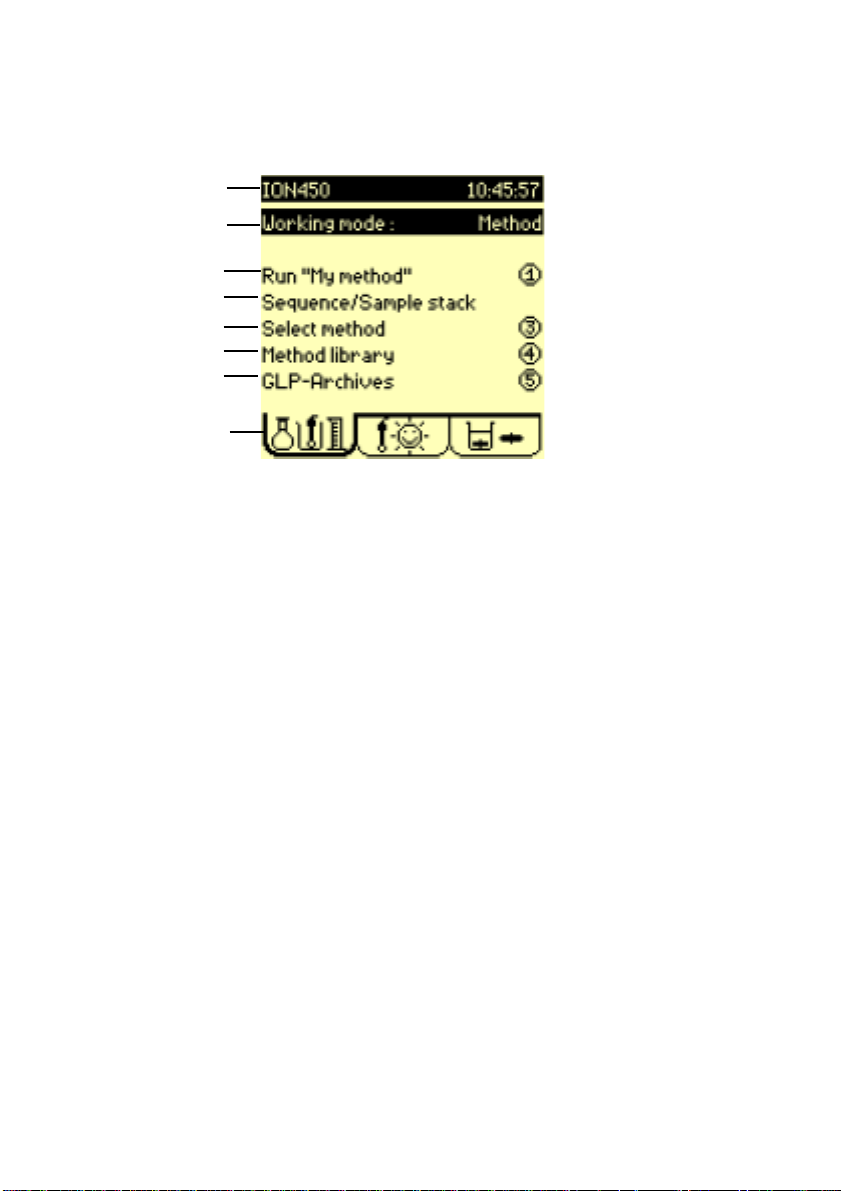
When the instrument is switched on the Main window is displayed.
1
2
3
4
5
6
7
8
1. Title bar: indicates the instruments name and the current time.
2. Working mode: Select the way in which you want to work. Choose
from Method, SAC Method, Sequence, SAC Sequence ; refer to
previous page.
3. Check or Run: check or run the selected method /sequence. The
method can be run when a sunny icons is displayed in the Electrode
tab.
If a cloudy/stormy icon is displayed, activate the "Check"
command. The Ion Analyser will automatically guide you
through the necessary operations required to solve the
problem(s)
4. Sequence/sample stack: if SAC Sequence or Sac Method
has been selected in step 2 above. Program the sample stack.
Select or edit the method sequence.
5. Select method: select method to be used for the analyses.
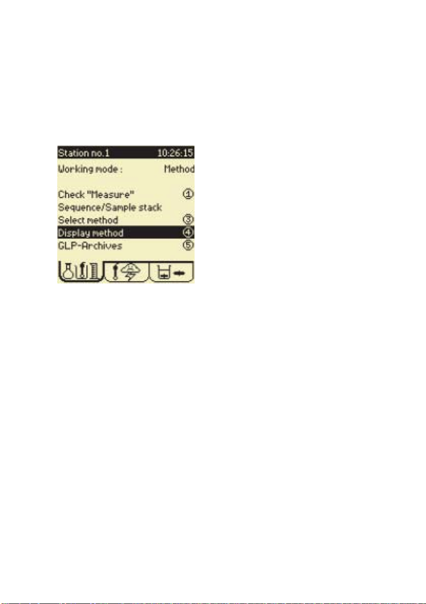
6. Method library: supervisor use only: create, edit, reset and delete
methods to correspond to your specific needs.
Or Display methods - routine use only : display the main
parameters of the selected method.
7. GLP-Archives: access GLP tables and visualise the stored method
sample results.
8. Method tab: Animated icon indicates when a method/sequence is
running.
.
14 Chapter 2
Page 15
Electrodes windowElectrodes window
Electrodes window
Electrodes windowElectrodes window
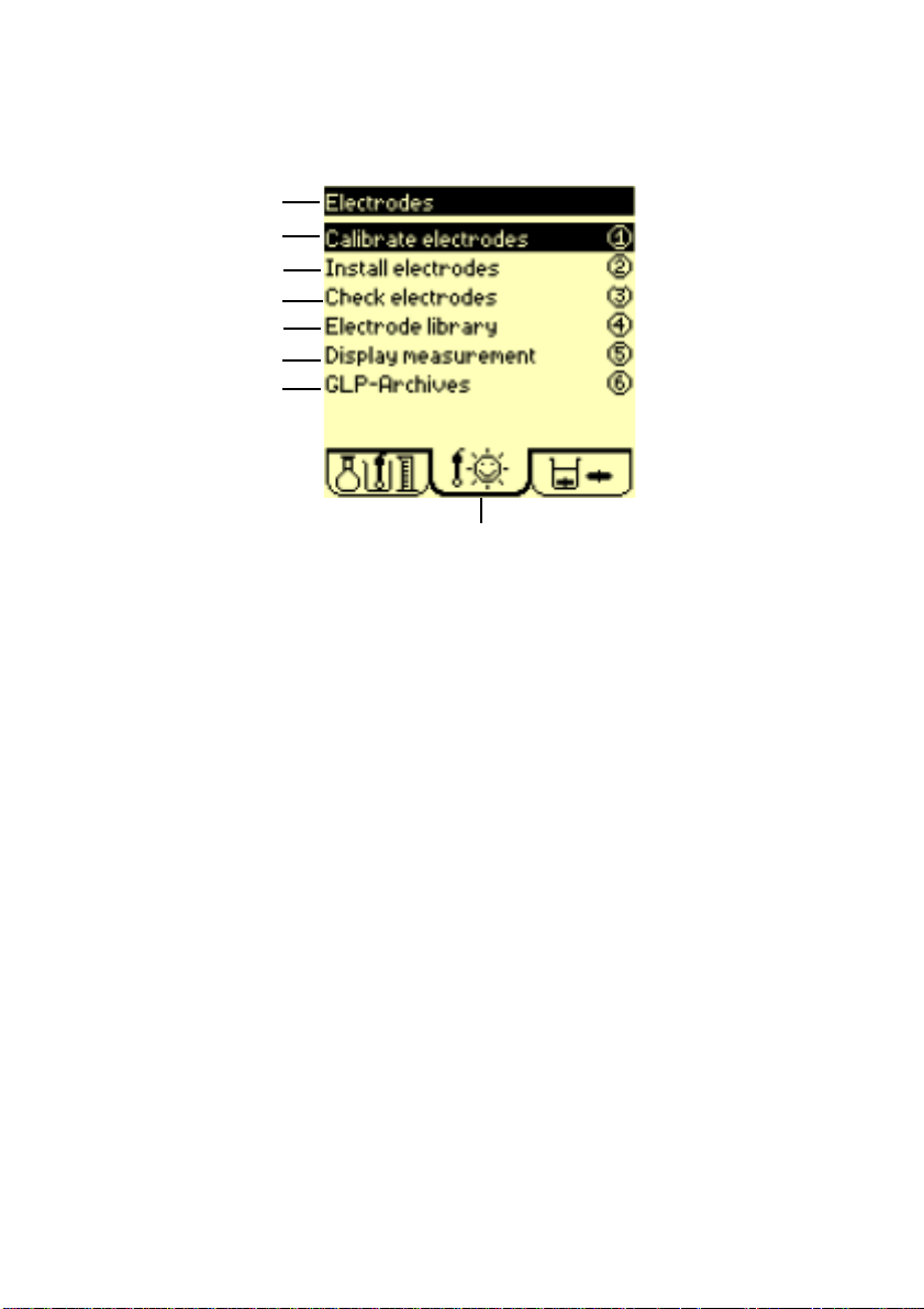
Use the RIGHT arrow key to move to this window.
1
2
3
4
5
6
7
8
1. Title bar: indicates the name of the window.
2. Calibrate electrode: run a calibration or a calibration sequence
using the installed electrodes.
3. Install electrodes: connect, disconnect or replace electrodes in a
method or sequence.
4. Check electrodes: check the identification parameters of the
electrodes used in the method or sequence.
5. Electrode library - Supervisor use only: create, edit, reset and
delete electrodes stored in the instrument.
6. Display measurement: displays mV and/or pH and/or concentration
and/or conductivity and/or temperature at a connected electrode of
the electrode system.
7. GLP-Archives: access GLP tables and visualise the stored
electrode calibration results.
8. Electrode tab: Electrode status icon indicates the state of the
electrode system. Four types of icons can be displayed.
Getting started 15
Page 16
Sunny icon. The calibration has been performed on all the
electrodes present in the system. Everything is just right!
Cloudy icon. The electrode calibration of one of the
electrodes present in the system should be performed
within 12 or 24 hours.
Stormy icon. The calibration date has elapsed for one of
the electrodes present in the system.
If acceptance limits have been set for the calibration: at
least one calibration result lies outside the programmed
acceptance limits.
At least one of the electrodes present in the system has
not been installed.
Check the sequence or method, (press 1 in the Main
window). The instrument prompts you to do the necessary
operations. You are guided step by step.
Question mark. There is a problem in the editing of the
electrode system. You need to be in Supervisor mode to
solve the problem. Check the sequence/method
or electrode parameters.
Check the sequence or method, (press 1 in the Main
window). The instrument indicates the possible errors and
prompts you to correct them until ? disappears.
16 Chapter 2
Page 17
Cell windowCell window
Cell window
Cell windowCell window
Use the RIGHT arrow key to move to this window.
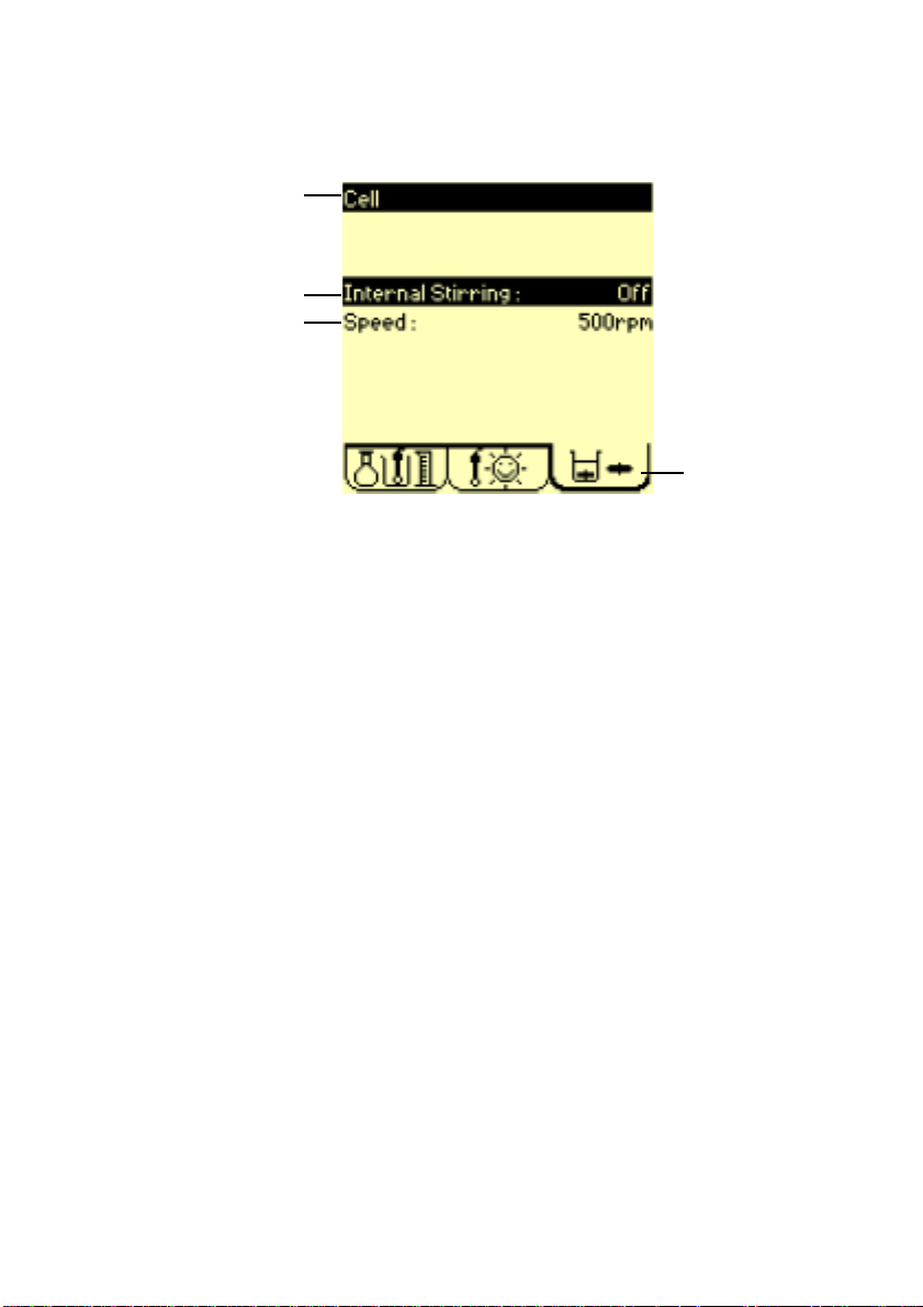
1
2
3
4
1. Title bar: indicates the name of the window.
2. Internal stirring: command stirrer On/Off.
3. Speed: select the internal stirring speed, from 100 to 1100 rpm by
steps of 50 rpm.
4. Cell tab: animated icon indicates when the magnetic stirrer or
propeller is operating.
Apply internal stirringApply internal stirring
Apply internal stirring
Apply internal stirringApply internal stirring
1. Select Internal stirring = ON,
2. Press ✓ in the field Speed and select a stirring speed.
Apply external stirringApply external stirring
Apply external stirring
Apply external stirringApply external stirring
1. Connect the Stirring Propeller, part no. 847-731, to the Ion Analyser
Propeller socket. Line 3 is automatically replaced by External
stirring.
2. Select External stirring = ON.
3. Adjust stirring by turning the stirring propeller knob. You can consult
the corresponding table between the position (1 to 9) and the stirring
speed by pressing ✓ in the field Speed setting.
Getting started 17
Page 18

System configurationSystem configuration
System configuration
System configurationSystem configuration
Proceed as follows to configurate your workstation
1. Press Stop for 3 seconds in the Main window to enter the Setup
menu.
2. Supervisor code:
Entering a Supervisor code enables you to differentiate
between the 2 operator modes: Routine and Supervisor:
In Routine mode, the user is able to select and run methods. In
Supervisor mode, the user can create, edit, select and run
methods. A Supervisor code is also used to protect your
parameters from any unwanted changes.
• Continue without entering a Supervisor code.
3. Press 1 to enter the Configuration menu.
Use the UP and
DOWN arrow
keys to select
the parameter.
Horizontal
scroll bar
The position of the bar indicates the first screen in the
Configuration menu. Use the RIGHT arrow key
to move to the next screen.
18 Chapter 2
Page 19

4. Press the RIGHT arrow key.
5. Press the UP arrow key.
The position of the bar indicates the
last screen in the
Configuration menu.
6. Press the LEFT arrow key to return to the first screen in the
Configuration menu.
Getting started 19
Page 20

Choosing the languageChoosing the language
Choosing the language
Choosing the languageChoosing the language
Choose your language for displays and printouts in the following way:
1. Use the UP and DOWN arrow keys to select the Language line.
2. Press ✓ to change a parameter as indicated at the bottom of the
screen.
3. Select the language.
Esc allows you to leave the screen without changing the language.
20 Chapter 2
Page 21

Setting the date and timeSetting the date and time
Setting the date and time
Setting the date and timeSetting the date and time
The current date and time are entered in the following displays:
1. Select Time.
Enter the hours (from 00 to 23).
2. RIGHT arrow key.
Enter the minutes (from 00 to 59).
3. RIGHT arrow key.
Enter the seconds (from 00 to 59).
The LEFT arrow key allows you to return to the previous screen to
modify an entered value.
4. Press ✓ to confirm (as indicated on the screen).
Getting started 21
Page 22

5. Select Date.
6. Press RIGHT arrow key.
7. Press RIGHT arrow key.
Enter the day (from 00 to 31).
Use the UP/DOWN keys to select the
month.
8. Press ✓.
22 Chapter 2
Enter the year (from 2000 to 2069).
Page 23

Customising the workstationCustomising the workstation
Customising the workstation
Customising the workstationCustomising the workstation
You can assign a name to your workstation, which will be permanently
displayed in the title bar of the Main window. Typing the name will allow
you to get used to using the instruments keypad.
1. Before leaving the Configuration menu:
• Select PC keyboard,
• select English (US).
This allows you to use a QWERTY keyboard.
2. Press Esc to return to the SETUP menu.
3. Press 3 (Customise).
4. Press
5. To replace "ION450" by "Chem.lab-1", proceed as follows:
✓✓
✓ to select the Station parameter.
✓✓
• Press 7 until the letter "C" appears, then release the key. The
cursor moves to the next position.
Getting started 23
Page 24

7
ABC
• Press 9 until the letter "h" appears.
• Continue until you have entered (em.lab-1).
• To correct a typing error, proceed as follows:
Press the LEFT arrow key to position the cursor on the letter
"E". Press 7 to enter the letter "A".
The letter E has been inserted between the letter "A" and the
letter "B".
Press Del to delete the "E".
• Press ✓ to confirm the entry.
24 Chapter 2
Page 25

6. You can also use a PC keyboard to enter alphanumeric characters.
• Connect the PC keyboard to the 6-pin plug situated on the left
hand side of the instrument.
• Select the line Radiometer Analytical. This line is used
to enter information concerning the workplace, user(s) name(s),
location, address etc.
• Enter the text using the PC keyboard (maximum of 32 characters
can be used).
If the characters shown on the display do not correspond to the
ones typed on the keyboard, redefine your keyboard type. To do
this, press Esc then 1 and select PC keyboard.
• Press ✓ to confirm.
You have now finished the getting started section. Press Esc to leave the
Customise screen, then press 5 to quit the SETUP menu.
Getting started 25
Page 26

26 Chapter 2
Page 27

3. Pr3. Pr
3. Pr
3. Pr3. Pr
Only the Supervisor is allowed to program the menus, Electrode and
Method.
To select the Supervisor mode, press Stop for 3 seconds in the Main
window and enter the Supervisor code. Press 5 (Exit) and select Return in
mode = Supervisor.
For first time users, it is recommended to program the Ion Analyser as
follows:
1. Create the electrode(s) to be used to perform the measurements.
Then finally,
2. Create the method(s), which will consequently use the electrode(s)
created in the first step of programming.
Once you have finished programming, make sure that NO question
marks "?" are displayed in the Electrode tab!
ogramming guidelinesogramming guidelines
ogramming guidelines
ogramming guidelinesogramming guidelines
✶
IMPORTANT
✶
Programming guidelines 27
Page 28

Create an electrodeCreate an electrode
Create an electrode
Create an electrodeCreate an electrode
1. Press 4 Electrode Library, then 1 New electrode.
2. Press ✓ in the Function field and select the function of the
electrode, refer to the table below:
Electrode type Select function
pH single p H
pH combined w/wo temp. sensor p H
Single metal/redox mV (i=0)
Combined metal/redox w/wo temp. sensor mV (i=0)
ISE single ISE or mV (i=0)
ISE combined w/o temp. sensor ISE or mV (i=0)
Conductivity cell w/o temp. sensor Conductivity
Reference single Reference
Temperature sensor T°C
Ground metal Ground
Double metal mV (i > 0)
3. Press ✓ in the ID field.
4. Select Other in the From field.
The option
electrode from a list of Radiometer Analytical electrodes.
5. Enter the identification (ID) of the electrode, (up to 16 characters).
6. Press 1 twice.
From = Catalogue
allows you to create an
28 Chapter 3
Page 29

7. Select the electrode Type, for electrodes with pH, mV or ISE
functions:
• Single pH - pH electrode (no reference part),
• Combined pH - pH electrode with a reference part (with or
without temperature sensor),
• Single metal/redox - mV (i=0) function electrode with a
reference part,
• Combined metal/redox - mV (i=0) function electrode with a
reference part (with or without temperature sensor),
• Single ISE - ISE or mV (i=0) function ion selective electrode
with no reference part,
• Combined ISE - ISE or mV (i=0) function ion selective
electrode with a reference part (with or without temperature
sensor).
8. When a combined electrode or a conductivity cell has been
defined, the instrument will prompt you to specify if it has a built-in
temperature sensor or not.
When a single electrode has been defined, the instrument will
prompt you to define a reference electrode in the Edit
electrode screen.
9. When a combined or a reference electrode has been defined,
enter the potential (in mV) of the reference element versus the
Standard Hydrogen Electrode (SHE).
This parameter enables to run calibration with automatic buffer
recognition when working with different reference electrode systems.
10. When a combined pH or a single pH electrodes has been defined,
enter the internal pH of the electrode (pH int).
11. For ISE electrodes only; enter the ion valency and molar weight
(in g/mol).
12. For conductivity cells only; enter the cable resistance (in Ω) and
capacitance (in pF).
13. Press 1 to confirm.
14. Edit the electrode parameters (see next page).
Programming guidelines 29
Page 30
Edit electrode screenEdit electrode screen
Edit electrode screen
Edit electrode screenEdit electrode screen
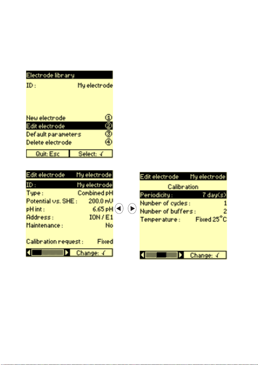
1. Press 4 Electrode library.
2. Press ✓ and select the electrode to be edited from the list.
3. Press 2 Edit electrode.
4. Edit the necessary parameters.
a. Electrode address: indicates which socket the electrode is con-
nected to:
ION / E1, E2, Ref, Temp, GND, Pt-Pt or EC (socket of the Ion
Analyser).
b. If you want a message to be displayed once a week upon starting a
method or a sequence of methods using this electrode, select
Maintenance = Yes and enter the message (3 lines of 32
characters maximum). This message can remind you to check or to
clean an electrode.
30 Chapter 3
Page 31

c. For a pH electrode or a conductivity cell, select the calibration
mode:
- Calibration request = No: the electrode parameter
edition is completed.
- Calibration request = Fixed : In this calibration
mode, the electrode is calibrated with standards that belong to
to a list of predefined values. Moreover, for a pH electrode, the
buffers/standards are automatically recognised.
The buffer/standards are chosen during method edition.
- Calibration request = Free: the buffer/standard
values are entered FREEly by the user. Use this option to
calibrate pH electrode or conductivity cells with buffers/
standards that do not belong to the predefined list.
For an ISE electrode, select the calibration mode:
- Calibration = No: the electrode parameter edition is
completed.
- Calibration = Manual : calibration using 1 to 9
standards of known concentration.The standard concentrations
are entered during method edition. This method requires 1 to 9
calibration beakers.
d. Enter the Periodicity.
Indicates the maximum period of time between two calibrations. If
the period of time is exceeded:
- pH measurements can no longer be performed using this pH
electrode,
- concentration measurement using a Direct ISE method can no
longer be performed using this ISE electrode.
- conductivity measurements can no longer be performed using
this conductivity cell.
In all cases, the electrode must be calibrated.
e. Enter the Number of cycles.
Enter the number of times the calibration should be repeated. This
is the number of beakers to be prepared for a given standard. For
each standard, the result will be calculated from the mean measured
value.
Programming guidelines 31
Page 32

f. Enter the Number of buffers or
Number of solutions
Enter the number of buffers (1 to 5 ) to be used for the pH electrode
calibration or enter the number of standards (1 to 9) to be used for
an ISE calibration.
g. Specify if a temperature sensor is in use.
If a temperature sensor is in use, select Probe.
If the temperature is entered manually via the numeric keypad,
select Entered.
If the calibration is to be performed at 25°C, select Fixed 25°C.
If you have selected Temperature = Probe, a temperature
sensor must have been selected in the Parameters screen.
.
32 Chapter 3
Page 33

Programming electrode parametersProgramming electrode parameters
Programming electrode parameters
Programming electrode parametersProgramming electrode parameters
1. If Calibrate request = yes, enter the electrode definition
parameters and go to the last Edit electrode screen.
2. Press 1:
To enter Calibration parameters: general parameters
used during the calibration,
3. Press 2:
To enter Calibration solutions , Calibration
points or Standard parameters concerning the standards
used for the calibration.
4. Press 3:
To enter the Results parameters concerning acceptation criteria
that you can set on the results.
5. Press 4:
To enter Printouts parameters defining the calibration report to
be printed.
Programming guidelines 33
Page 34
Create a methodCreate a method
Create a method
Create a methodCreate a method
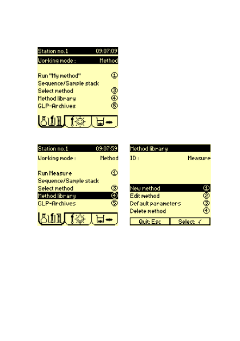
1. Press ✓ and select Method.
2. Press 4 Method library then 1 New method.
3. Press ✓ in the ID field.
4. Enter a method name (up to 16 characters).
5. Press 1.
6. Edit the method parameters (see the next page).
34 Chapter 3
Page 35

Edit method screenEdit method screen
Edit method screen
Edit method screenEdit method screen
1. Press 4 Method library.
2. Press ✓, select the method to be edited from the list then press 2
Edit method.
3. Edit the necessary parameters.
a. Select the method mode. The modes available are:
• Measurement (pH or mV, ISE direct, conductivity or
conductivity/pH)
• Coupled (methods chained in a same beaker)
b. Select the measurement mode: pH, mV, mV(i>0), ISE direct,
conductivity or EC/pH (conductivity and pH measurements are
performed simultaneously)
Programming guidelines 35
Page 36

c. Select the way the temperature is to be measured.
• Probe: temperature sensor is required during measurements.
• Entered: temperature is to be entered manually using the
keypad.
• Fixed 25°C: measurements are assumed to be performed at
25°C.
d. Enter the Number of tests, i.e. the number of times the
method is to be repeated.
e. If you want a message to be displayed upon starting the method,
select Notification = Yes then enter the message (3
lines of 32 characters maximum).
f. Select the way the cell grounding of the measuring electrode will be
performed:
• Reference: reference electrode connected to the Ref
socket on the measurement system.
• Metal: metal electrode connected to the GND socket on the
measurement system. For measurements in very resistant
medium.
• Other: an electrode which does not belong to the electrode
system.
g. QC sample: the concentration of a QC sample is known accurately
and the composition is close as possible to that of the samples to
be analysed. QC measurements enable you to perform quality
control tests on the method used. Refer to the Reference Manual for
more information concerning this option. Select Yes for QC
sample to perform measurements on QC samples.
36 Chapter 3
Page 37

Programming method parametersProgramming method parameters
Programming method parameters
Programming method parametersProgramming method parameters
1. Go to the last Edit method screen.
2. Press 1:
To enter the Method parameters: general parameters
concerning the electrode used by the method.
3. Press 3:
To enter the Results parameters defining the results and the
acceptation criteria that you can set on the results.
4. Press 4:
To enter the Printouts: parameters defining the analysis report
to be printed.
5. Press 5:
To enter the QC data (only available when QC sample = Yes):
quality control parameters required when using QC samples.
Programming guidelines 37
Page 38

38 Chapter 3
Page 39

4. Running analyses4. Running analyses
4. Running analyses
4. Running analyses4. Running analyses
✶
IMPORTANT
Before pressing the Run key, check the following points listed below:
1. Select the method by pressing 3 in the main window.
2. If a Question mark "?" is present in the electrode tab.
Programming error due to missing electrode parameters.
Contact your supervisor.
✶
3. Connect/Check electrode(s).
When installing/checking an electrode system, do not forget to
connect all the installed electrodes to the ION450 sockets and to
install these electrodes on the ION450 (Location = ION) or the
SAC80 or SAC90 Sample Changer (Location = SAC).
It is important to immerse, in the same measuring beaker, all the
installed electrodes having the same location.
For example: conductivity and pH measurements.
If your installed electrode system comprises either a conductivity
cell or a double platinum electrode with a combined pH electrode, the
electrodes must remain permanently immersed in the same beaker,
in order to measure the pH correctly. This is because it is the
conductivity cell (or the double platinum electrode) that provides the
connection to the ground and not the reference electrode.
This so-called " 3-electrode or differential measurement configuration
" will stop the conductivity cell altering the measurement at the pH
electrode.
When using this configuration for an electrode calibration, the
conductivity cell and the pH electrode must always be immersed in
the same beaker.
Important: Never remove an electrode or an electrode system
without running the Installation/checking procedure first. The
instrument needs to know its configuration at any time.
Refer to Short-Form Reminder no. 1.
For more information, refer to the ION450 Reference Manual,
keyword index: "Electrode connection - Important".
Running analyses 39
Page 40

4. Run the analysis when a Sunny icon is visible in the electrode tab.
5. Run an electrode calibration when a Stormy icon appears in the
electrode tab.
6. If you are unable to display the "Run" command due to the presence
of Cloudy/Stormy icons in the Electrode tab, activate the "Check"
command. The Ion Analyser will automatically guide you through
the necessary operations required to solve the problem(s).
Run electrode calibrationRun electrode calibration
Run electrode calibration
Run electrode calibrationRun electrode calibration
Refer to Short-Form Reminder no. 3
1. Select the method and install the electrode group.
2. Enter the Electrodes window.
3. Select 1 Calibrate electrode. Press ✓ to select the
electrode to be calibrated from the proposed list.
4. Press 1 to start the calibration.
Run methodRun method
Run method
Run methodRun method
Refer to Short-Form Reminder no. 4.
1. Select the method in the Method library and install the
electrode group to be used to perform the analysis.
.
2. Display the Main window.
3. Press 1 to start the analysis.
Run direct measurementRun direct measurement
Run direct measurement
Run direct measurementRun direct measurement
Refer to Short-Form Reminder no. 6.
1. Select the method and install the electrode group to be used to
perform the measurement.
2. Prepare the sample solution and place on the sample stand.
3. Display the Electrodes window.
4. Press 5 to start the measurement.
5. Select the electrode in the list of connected electrodes. You can
stop or start stirring by pressing 1.
40 Chapter 4
Page 41

5. V5. V
5. V
5. V5. V
How to access?How to access?
How to access?
How to access?How to access?
The GLP-Archives (Good Laboratory Practice) command is available in
each window:
• Main: press 5 to access,
The GLP-Archives window displays the method, electrode ID with
the electrode installation date.
iewing dataiewing data
iewing data
iewing dataiewing data
Electrodes: press 6 to access.
Press ✓ and enter the result
number from where you want to
start visualising the results.
Example: result no. 9 out of 26
results stored for the method
selected.
Press 1 to consult.
The following pages give a
summary of the information
available in the Main and
Electrodes windows.
Viewing data 41
Page 42

Sample resultsSample results
Sample results
Sample resultsSample results
The last 200 sample results are saved in the archives.
Once you have selected the method and the result (see previous page),
the following data are displayed:
Result no. 9 / 26 Result no. 10 / 26
26 is
the
number
of
results
saved
for the
selected
method.
Scroll the results.
The results can be: Test results (Rx) or Average ± standard deviation
calculated on several tests of the same sample. "ION" or "SAC" means that an
ION or a SAC method has been run. "CPL, ION" or "CPL, SAC" means that the
method run belongs to an ION or SAC coupled method.
1
Mean and standard deviation
calculated on three R1
accepted test results.
42 Chapter 5
1
R1 = result of test no. 3 (test
accepted).
Page 43

Electrode calibration resultsElectrode calibration results
Electrode calibration results
Electrode calibration resultsElectrode calibration results
The last 100 electrode calibration results are saved in the archives.
Once you have selected the electrode then the result (see first page of
this chapter), the following data are displayed (for a pH calibration):
Result no. 13 / 19
19 is
the
number
of
results
saved
for the
selected
electrode.
Scroll the results.
The results can be: cycle performed on a standard, mean calculated on several
cycles performed on the same standard or current calibration data. "ION" or
"SAC" means that an ION or a SAC method has been run.
1
Result no. 14 / 19
1
Mean calculated on 3 cycles
performed and accepted. Each
cycle has been run using 2 buffer
solutions.
Result of cycle no. 3 (cycle
accepted). This cycle has been
run using 2 buffer solutions.
Viewing data 43
Page 44

44 Chapter 5
Page 45

6. Printing data6. Printing data
6. Printing data
6. Printing data6. Printing data
✶
IMPORTANT
Before printing, it is necessary to perform the following:
1. Enter the Setup window: press Stop 3 seconds in the Main
window.
2. Select the Printer
Press 1.
In Configuration, select Printer = 80 columns and
Format = Listing or Page by Page.
3. Enter User ID (if required)
In Configuration, select User ID = Yes. You will be
prompted to enter a user ID at the start of a run method. This ID will
appear on the printouts.
4. Customise the printout (if required)
In Configuration, press 3.
In Customise, enter the name of your workstation (max. 4 lines
of 32 characters). This information will appear as a header at the
start of the printout.
✶
5. For automatic printout - select a condensed or detailed printout
In the Printouts screen of the Edit method/electrode, select
Detailed = High to obtain a full detailed printout.
Select Low for condensed printout.
Printing data 45
Page 46

Manual printoutsManual printouts
Manual printouts
Manual printoutsManual printouts
Method libraryMethod library
Method library
Method libraryMethod library
Press Print, in the Main window to give you an overview of the methods
available in the method list.
Electrode libraryElectrode library
Electrode library
Electrode libraryElectrode library
Press Print, in the Electrode window to give you an overview of the
electrodes available in the electrode list.
46 Chapter 6
Page 47

Edit method dataEdit method data
Edit method data
Edit method dataEdit method data
In the Main window, press 4 Method library then Print to give you
an overview of the parameters of the current programmed method. These
are the parameters entered in the Edit method screen (press 2 to
access).
Edit electrode dataEdit electrode data
Edit electrode data
Edit electrode dataEdit electrode data
Press 4 Electrode library in the Electrode window then
Print to give you an overview of the parameters of the current
programmed electrode. These are the parameters entered in the Edit
electrode screen (press 2 to access).
Printing data 47
Page 48
Automatic printoutsAutomatic printouts
Automatic printouts
Automatic printoutsAutomatic printouts
The Print key is inactive during a sample measurement or an
electrode calibration.
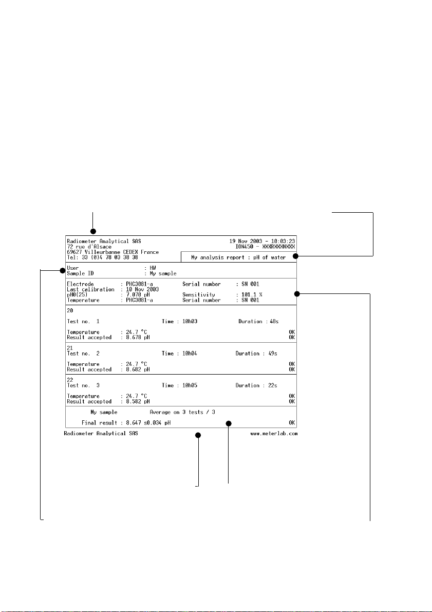
The results obtained during a "Run" are printed automatically.
Depending on the option selected for Detailed in the Edit method/
electrode - Printout window, you will obtain different types of printouts.
Example of a printout for a pH measurement method
Header: information entered
in the Customise screen
of the Setup window.
Title of report:
entered in
Printouts
screen during
method editing
Foot note: automatically appears
at the end of all printouts
Analysis ID: User ID and Sample
ID entered at the start of the
measurement (if option selected
during editing)
48 Chapter 6
Result: obtained at the end of
the analysis
Calibration data: of the electrode
used
Page 49

7. Connection of peripherals7. Connection of peripherals
7. Connection of peripherals
7. Connection of peripherals7. Connection of peripherals
Combined pH electrodes
w/wo temperature sensor
Single pH electrodes
Single or combined metal
electrodes (Redox
measurements)
Single or combined ion
selective electrodes
Conductivity cell
Reference electrodes
Double metal electrodes
Temperature sensors
Single metal electrodes
for grounding only
Line cord, 230 V (A95S001),
115 V (A95S002)
PC, cable
A95X501
Printer, cables
A95P201/
A95X506
SAC80 or SAC90
Sample Changer,
cable A95A202
Not used
Connection of peripherals 49
Page 50

50 Chapter 7
Page 51

8. General infor8. General infor
8. General infor
8. General infor8. General infor
CleaningCleaning
Cleaning
CleaningCleaning
The instrument requires minimum maintenance. The exterior surface can
be cleaned with tepid water and wiped dry with a soft cloth. Never use
another solvent unless you have first consulted your
Radiometer Analytical representative
TT
ransporranspor
T
ranspor
TT
ransporranspor
Always use the packaging supplied by the manufacturer.
IMPORTANT!
Remove the metal rod before transporting the instrument.
Never pick-up or carry the instrument by the metal rod.
ServicingServicing
Servicing
ServicingServicing
DO NOT ATTEMPT TO SERVICE THIS PRODUCT YOURSELF,
except as noted in the Reference Manual. For servicing, please contact
your Radiometer Analytical service representative at the address given
below:
ting the instrumentting the instrument
ting the instrument
ting the instrumentting the instrument
mationmation
mation
mationmation
RADIOMETER ANALYTICAL SAS
72, rue d'Alsace
69627 Villeurbanne CEDEX - France
Tel.: +33 (0) 4 78 03 38 38
Fax: +33 (0) 4 78 03 38 27
E-mail: radiometer@nalytical.com
or your local service representative:
_________________________________
_________________________________
_________________________________
_________________________________
_________________________________
General information 51
Page 52

52 Chapter 8
 Loading...