

Page 1

ABL800 FLEX operator’s manual
Page 2

Page 3

ABL800 FLEX
operator’s
manual
Page 4

Page 5
Introduction
Instructions to
user
Note to users of the ABL800 FLEX analyzers
This note to users gathers changes from previous note to users in one document and
outlines some new changes to the operator’s manual of your ABL800 FLEX analyzer
(from software version 6.10).
Please remove the existing note to users from the binder of your manual and place this note
to users in the binder instead.
Brief overview
of the change
Interference –
new interference
results for ClO
4
USB connector
Changes/Description
Limitations of use and known interfering substances:
–
CAUTION - Known interfering substances
Substance Interference
ClO
–
(drugs)
4
For ClO
level), cCl
mmol/L level)
cCa
cCl
cK
– ,
interference on cCa2+ (1.25 mmol/L
4
(110 mmol/L level), and cK+ (4
has been detected:
2+
(1.25 mmol/L level): 0.27*
(110 mmol/L level): 4-30
+
(4 mmol/L level): 0.3.
* Depending on the pH level
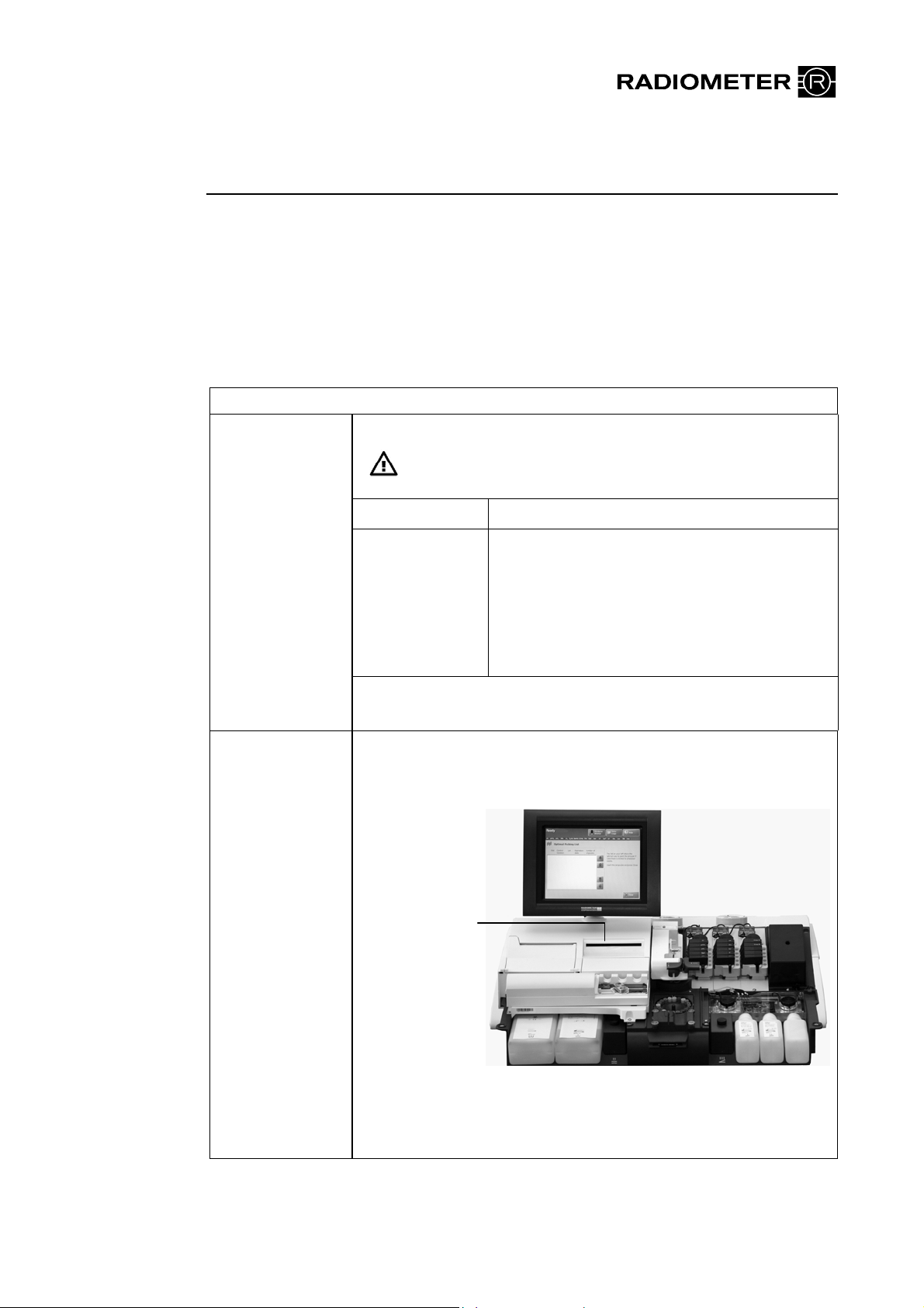
Instead of the CD-ROM drive, a USB connector may be available.
USB connector or
CD-ROM drive
The USB connector can be used for storing data on an USB flash
drive (memory stick) or for connecting USB devices. Can also be
used for installation of software.
Radiometer, the Radiometer logo, ABL, AQT, TCM, RADIANCE, PICO and CLINITUBES are
trademarks of Radiometer Medical ApS.
© 2011 Radiometer Medical ApS. All rights reserved. 995-950. 201104A.
Page 6

Measured
New table for pleural liquid:
parameters
Parameter Unit Measuring
Range
Test
range
pH pH scale 6.300-8.000 7.0-7.5*
* If the measured values obtained lie outside the test range,
Radiometer advises you to repeat the measurement by means of
another method.
Indoor use statement added according to CSA regulations: Environmental
requirements
Environmental
ratings
Clot detection A new feature is included in software version 6.06 of the following
Location Indoor use only
Pollution degree 2 statement added according to CSA regulations:
Installation category II.
Pollution degree 2.
products:
ABL7xx Series (XPE) analyzers
ABL800 FLEX analyzers
ABL800 BASIC analyzer.
The new feature enables the analyzer to detect clots caught in the
measurement chamber under the pH electrode. This document
describes it.
When to activate the clot-detection feature
It is especially beneficial to activate the clot detection feature in
analyzers frequently used to analyze samples known to be prone to
clotting, for example, samples drawn from umbilical cords. Once
activated clot detection is active during all sample measurements.
NOTICE: It is important to note that activating the feature will
delay measurement results by approximately one minute, even
though it only increases the measurement cycle time by five
seconds. It also increases consumption of Rinse solution, but this is
minimal.
Page 7

To activate the clot-detection feature
Contact a Radiometer representative and request that clot detection
be enabled via the service program.
Clot-detection process
During calibration the measuring chamber is rinsed and the pH of
the Rinse solution is measured. The value is stored in the analyzer.
During a sample measurement the measuring chamber is also rinsed
and the pH of the rinse solution is measured and compared with the
pH value stored during the last calibration. If the difference between
these values (the pH drift) exceeds a pre-determined maximum
value, it could indicate the presence of a clot beneath the pH
electrode.
When enabled, the clot-detection feature can generate three new
messages that are listed below.
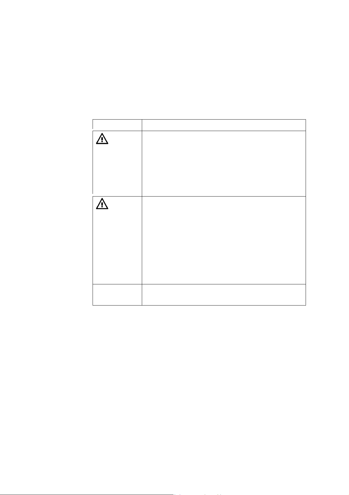
Analyzer messages
NOTICE: Operator actions are listed in order of priority. Perform
the first action in the list and the actions indicated in the "Removal
condition(s) list. If the message persists, perform the next listed
action and the actions indicated in the "Removal condition(s) list,
and so on.
No. Message Interpretation Operator action(s)
1025
Clot suspected
beneath pH
electrode*
The difference
between the pH of
the rinse solution,
measured during the
sample measurement,
and that stored after
the last calibration
exceeds the
Remove the pH electrode and
check the measuring chamber for
clots: clean the measuring
chamber with a cotton stick
moistened with distilled water.
Make sure no cotton fibers are
left in the measuring chamber
Clean pH electrode
maximum al l owable
drift.
This indicates the
presence of a clot in
the measuring
chamber beneath the
pH electrode.
Remembrane Ref electrode
Replace pH electrode
Perform a 1- or 2-point calibration
Removal condition(s):
Acknowledge execution of the
"Clot removal procedure"
Successful 1- or 2-point
calibration
* NOTICE: This is a system message.
Page 8
1026 Clot (pH)
detection not
possible
The pH of the rinse
solution - stored
during the latest
calibration - was
invalidated when
either the Rinse
solution was
replaced, or when
maintenance was
performed on an
electrode.
A new pH value
needs to be
established by
performing a
calibration.
Perform a 1- or 2-point
calibration.
Removal condition(s):
Successful 1- or 2-point
calibration.
1027 Clot suspected
beneath pH
electrode
Acknowledging
execution of a
"Clot-removal
procedure"
The difference
between the pH of
the rinse solution,
measured during the
sample measurement,
and that stored after
the last calibration
exceeds the
maximum al l owable
drift.
This indicates the
presence of a clot in
the measuring
chamber beneath the
pH electrode.
Step Action
Press Analyzer status > Electrodes and others.
1.
Press Replace.
2.
Remove the pH electrode and
check the measuring chamber for
clots: clean the measuring
chamber with a cotton stick
moistened with distilled water.
Make sure no cotton fibers are
left in the measuring chamber
Clean pH electrode
Remembrane Ref electrode
Replace pH electrode
Perform a 1- or 2-point calibration
Removal condition(s):
Acknowledge execution of the
"Clot removal procedure"
Successful 1- or 2-point
calibration
Technical
documentation
Press Clots removed.
3.
Data in this document will be added to the manual next time it is updated.
Radiometer Medical ApS
Åkandevej 21
2700 Brønshøj
Denmark
www.radiometer.com
Page 9

Table of contents
ABL800 FLEX
Operator’s manual
1. Introduction
2. What is what
3. Installation and setup
4. Sample measurements
5. Quality control
6. Calibration
7. Replacements
8. Disk functions
9. Data management
10. Analyzer shutdown
11. Troubleshooting
12. Sampling
13. Specifications
14. Ordering information
15. Radiometer settings
Index - Date of issue
Page 10

System performance
The procedures described in this manual must be observed in order to ensure proper system
performance, and to avoid hazards.
Radiometer cannot provide or verify system performance characteristics if the system is not installed,
used and maintained in accordance with Radiometer procedures or if accessories not meeting the
specifications provided by Radiometer are used.
Radiometer warrants that the data media on which the software included in the system is furnished is
free from defects in material and workmanship under normal use for three (3) months from the date of
delivery as evidenced by a copy of invoice or receipt.
Third-party software and trademarks
The ABL800 FLEX analyzers comprise the Microsoft WindowsXP Embedded, VxWorks and
Sybase SQL Anywhere software.
By using the system, you accept the terms of the Software License Agreement(s) of the provider(s) of
the above software as shown in the End User License Agreement(s) in the analyzer start up picture and
to the terms of the Microsoft WindowsXP Embedded End-User Agreement included in this manual. If
you cannot accept the terms of the Software License Agreement(s), you should not use the system, but
immediately contact your provider for a return of the system and a refund of the purchase price.
Microsoft® and Windows® are trademarks of Microsoft Corporation.
VxWorks is a registered trademark of WindRiver Systems Incorporated.
Sybase SQL Anywhere is a registered trademark of Sybase Incorporated.
Warranties and disclaimer
Radiometer makes no warranties, express or implied, other than expressly stated.
Any warranties expressly stated in this document are conditional upon the system being installed, used
and maintained in accordance with Radiometer procedures, incl uding that only accessories meeting the
specifications provided by Radiometer are used.
Radiometer disclaims any liability for system performance if the system is not installed, used and
maintained in accordance with Radiometer procedures or if accessories not meeting the specifications
provided by Radiometer are used.
Further, Radiometer disclaims any liability for loss of data and direct, consequential or other damages,
including loss of profit or loss of business, whether such claim for damages is based upon contract,
negligence or tort (including strict liability), and even if Radiometer has knowledge of the possibility of the
potential damage or loss.
Confidentiality
The contents of this document shall not be reproduced or communicated to any third party without the
prior written consent of Radiometer.
Changes
This document is subject to change without notice and you are urged to contact Radiometer to verify
whether the document has been changed.
While every effort is made to ensure the correctness of the information provided in this document as
changed from time to time, Radiometer disclaims any liability for errors and omissions.
Radiometer, the Radiometer logo, ABL, AQT, TCM, RADIANCE, PICO and CLINITUBES are trademarks of
Radiometer Medical ApS.
© 2011 Radiometer Medical ApS. All rights reserved.
Page 11

TEnd-User License Agreement for the ABL800 FLEX Analyzers
You have acquired a device ("DEVICE") THAT INCLUDES SOFTWARE LICENSED BY Radiometer
Medical ApS from Microsoft Licensing Inc. or its affiliates ("MS"). Those installed software products of
MS origin, as well as associated media, printed materials and "online" or electronic documentation
("SOFTWARE") are protected by international intellectual property laws and treaties. The SOFTWARE
is licensed, not sold. All rights reserved.
IF YOU DO NOT AGREE TO THIS END-USER LICENSE AGREEMENT ("EULA"), DO NOT USE
THE DEVICE OR COPY THE SOFTWARE . INSTEAD, PROMPTLY CONTACT THE SUPPLIER OF
THE INSTRUMENT FOR INSTRUCTIONS ON RETURN OF THE UNUSED DEVICE(S) FOR A
REFUND. ANY USE OF THE SOFTWARE, INCLUDING BUT NOT LIMITED TO USE ON THE
DEVICE WILL CONSTITUTE YOUR AGREEMENT TO THIS EULA (OR RATIFICATION OF ANY
PREVIOUS CONSENT).
GRANT ON SOFTWARE LICENSE. This EULA grants you the following license:
• You may use the SOFTWARE only on the DEVICE.
• NOT FAULT TOLERANT. THE SOFTWARE IS NOT FAULT TOLERANT. RADIOMETER
MEDICAL ApS HAS INDEPENDENTLY DETERMINED HOW TO USE THE SOFTWARE IN THE
DEVICE, AND MS HAS RELIED UPON RADIOMETER MEDICAL ApS TO CONDUCT
SUFFICIENT TESTING TO DETERMINE THAT THE SOFTWARE IS SUITABLE FOR SUCH
USE.
• NO WARRANTIES FOR THE SOFTWARE. THE SOFTWARE is provided "AS IS" and with all
faults. THE ENTIRE RISK AS TO SATISFACTORY QUALITY, PERFORMANCE, ACCURACY,
AND EFFORT (INCLUDING LACK OF NEGLIGENCE) IS WITH YOU. ALSO, THERE IS NO
WARRANTY AGAINST INTERFERENCE WITH YOUR ENJOYMENT OF THE SOFTWARE OR
AGAINST INFRINGEMENT. IF YOU HAVE RECEIVED ANY WARRANTIES REGARDING THE
DEVICE OR THE SOFTWARE, THOSE WARRANTIES DO NOT ORGINATE FROM, AND ARE
NOT BINDING ON, MS.
• Note on Java Support. The SOFTWARE may contain support for programs written in Java. Java
technology is not fault tolerant and is not designed, manufactured or intended for use or resale as
online control equipment in hazardous environments requiring fail-safe performance, such as in
the operation of nuclear facilities, aircraft, navigation or communication systems, air traffic control,
direct life support machines or weapons systems, in which the failure of Java could lead directly to
death, personal injury, or severe physical or enviromental damage. Sun Microsystems, Inc. has
contractually obligated MS to make this disclaimer.
• No Liability for Certain Damages. EXCEPT AS PROHIBITED BY LAW, MS SHALL HAVE NO
LIABILITY FOR ANY INDIRECT, SPECIAL, CONSEQUENTIAL OR INCIDENTAL DAMAGES
ARISING FROM OR IN CONNECTION WITH THE USE OR PERFORMANCE OF THE
SOFTWARE. THIS LIMITATION SHALL APPLY EVEN IF ANY REMEDY FAILS OF ITS
ESSENTIAL PURPOSE. IN NO EVENT SHALL MS BE LIABLE FOR ANY AMOUNT IN
EXCESS OF US. TWO HUNDRED FIFTY DOLLARS (US$250.00).
• Limitations on Reverse Engineering, Decompilation and Disassembly. You may not reverse
engineering, decompile, or disassemble the SOFTWARE, except and only to the extent that such
activity is expressly permitted by applicable law notwithstanding this limitation.
• SOFTWARE TRANSFER ALLOWED BUT WITH RESTRICTIONS. You may permanently
transfer rights under this EULA only as a part of a permanent sale or transfer of the DEVICE, and
only if the recipient agrees to this EULA. If the SOFTWARE is an upgrade, any transfer must also
include all prior versions of the SOFTWARE.
• EXPORT RESTRICTIONS. You acknowledge that SOFTWARE is of US-origin. You agree to
comply with all applicable international and national laws that apply to the SOFTWARE, including
the US Export Administration Regulations, as well as end-user, end-use and country destination
restrictions issued by US and other governments. For additional information on exporting the
SOFTWARE, see
http://www.microsoft.com/exporting/.
Page 12

Page 13

Contents
This manual contains the following topics.
1. Introduction...................................................................................................... 1-1
Overview........................................................................................................... 1-1
Names and intended use.................................................................................... 1-2
Limitations of use and known interfering substances....................................... 1-4
Warning/Caution and Notices........................................................................... 1-7
Symbols overview............................................................................................. 1-8
2. What is what ..................................................................................................... 2-1
Overview........................................................................................................... 2-1
Analyzer - front................................................................................................. 2-2
Analyzer - rear .................................................................................................. 2-4
Measuring section.............................................................................................2-5
Inlet module......................................................................................................2-7
FLEXQ module................................................................................................. 2-8
Thermal printer ............................................................................................... 2-10
Communication ports...................................................................................... 2-11
Barcode reader................................................................................................ 2-13
AutoCheck module ......................................................................................... 2-14
Screen elements .............................................................................................. 2-15
Menu structure................................................................................................ 2-24
Analyzer status................................................................................................ 2-28
Online aid facilities......................................................................................... 2-36
Sample counter................................................................................................ 2-39
3. Installation and setup....................................................................................... 3-1
Overview........................................................................................................... 3-1
Installation ........................................................................................................ 3-2
Setup menu structure......................................................................................... 3-3
Analyzer security.............................................................................................. 3-6
Analysis setup................................................................................................. 3-13
Patient reports ................................................................................................. 3-26
Calibration setup............................................................................................. 3-32
Quality control setup....................................................................................... 3-35
Replacement setup.......................................................................................... 3-48
Page 14

Contents ABL800 FLEX Operator's Manual
Parameters and input setup ............................................................................. 3-55
Analyzer settings............................................................................................. 3-62
Communications............................................................................................. 3-68
Printers............................................................................................................ 3-77
Disk Functions setup....................................................................................... 3-80
Corrective actions ........................................................................................... 3-83
Miscellaneous setup........................................................................................ 3-86
4. Sample measurements...................................................................................... 4-1
Overview........................................................................................................... 4-1
General information.......................................................................................... 4-2
Immediately before analysis ............................................................................. 4-9
Measurements with FLEXQ ........................................................................... 4-10
Introducing a blood sample............................................................................. 4-12
Introducing a pleura sample............................................................................ 4-15
Introducing an expired air sample................................................................... 4-16
Patient identification....................................................................................... 4-17
Patient result ................................................................................................... 4-21
Calculation of FShunt and ctO2(a -
_
) ........................................................... 4-25
V
Patient result messages.................................................................................... 4-26
5. Quality control.................................................................................................. 5-1
Overview........................................................................................................... 5-1
General information.......................................................................................... 5-2
Preparing a control solution.............................................................................. 5-4
Manual quality control measurement................................................................ 5-6
AutoCheck measurement.................................................................................. 5-7
Quality control identification............................................................................ 5-8
Quality control result ...................................................................................... 5-10
Quality control result messages ...................................................................... 5-15
6. Calibration........................................................................................................ 6-1
Overview........................................................................................................... 6-1
General information.......................................................................................... 6-2
Unscheduled calibrations.................................................................................. 6-4
Interrupted, pending or expired calibrations..................................................... 6-5
tHb calibration .................................................................................................. 6-6
Calibration result............................................................................................... 6-8
Calibration result messages............................................................................. 6-10
Page 15

ABL800 FLEX Operator's Manual Contents
7. Replacements .................................................................................................... 7-1
Overview........................................................................................................... 7-1
General information.......................................................................................... 7-2
Replacing membranes or electrodes.................................................................. 7-6
Replacing pump tubes....................................................................................... 7-9
Replacing inlet gasket unit and inlet probe..................................................... 7-12
Replacing waste container, fan filter, printer paper........................................ 7-14
Replacing solutions and gases ........................................................................ 7-16
Refilling the AutoCheck carousel................................................................... 7-19
Automatic auxiliary programs ........................................................................ 7-20
Decontamination and Protein Removal programs.......................................... 7-21
Cleaning the analyzer...................................................................................... 7-23
List of references............................................................................................. 7-25
8. Disk Functions .................................................................................................. 8-1
Overview........................................................................................................... 8-1
General information.......................................................................................... 8-2
Creating a WDC report..................................................................................... 8-4
Backing up all data............................................................................................ 8-6
Restoring all data .............................................................................................. 8-8
Exporting data logs........................................................................................... 8-9
Importing/exporting archives.......................................................................... 8-11
Saving setup.................................................................................................... 8-13
Loading/restoring setup .................................................................................. 8-14
9. Data management............................................................................................. 9-1
Overview........................................................................................................... 9-1
General information.......................................................................................... 9-2
Patient Results Log........................................................................................... 9-4
Patient Profiles Log........................................................................................... 9-7
Quality Control Log........................................................................................ 9-11
Calibration Log............................................................................................... 9-17
Activity Log.................................................................................................... 9-20
Replacement Log............................................................................................ 9-23
Archived data logs .......................................................................................... 9-24
RADIANCE browser (optional) ..................................................................... 9-26
10. Analyzer shutdown......................................................................................... 10-1
Overview......................................................................................................... 10-1
General information........................................................................................ 10-2
Page 16

Contents ABL800 FLEX Operator's Manual
Standby mode ................................................................................................. 10-3
Full waste container........................................................................................ 10-5
Temporary Shutdown...................................................................................... 10-6
Long Term Shutdown..................................................................................... 10-8
11. Troubleshooting.............................................................................................. 11-1
Overview......................................................................................................... 11-1
General information........................................................................................ 11-2
Forced Hold causes......................................................................................... 11-5
Analyzer messages.......................................................................................... 11-7
Fluid transport troubleshooting procedure.................................................... 11-74
Inlet probe troubleshooting procedure.......................................................... 11-75
Inlet troubleshooting procedure.................................................................... 11-76
Leak troubleshooting procedure ................................................................... 11-77
Electrode troubleshooting procedures........................................................... 11-78
Pump troubleshooting procedure.................................................................. 11-80
Fluid transport system description................................................................ 11-81
12. Sampling.......................................................................................................... 12-1
Overview......................................................................................................... 12-1
Causes of errors in preanalytical phase........................................................... 12-2
Preparation prior to arterial/venous sampling................................................. 12-5
Preparation prior to capillary sampling........................................................... 12-7
Sampling devices............................................................................................ 12-8
Storage and preparation prior to analysis........................................................ 12-9
Sampling procedures..................................................................................... 12-12
References..................................................................................................... 12-15
13. Specifications .................................................................................................. 13-1
Overview......................................................................................................... 13-1
Measured parameters ...................................................................................... 13-2
Input parameters.............................................................................................. 13-5
Derived parameters......................................................................................... 13-6
Sample handling.............................................................................................. 13-8
Calibration and maintenance programs......................................................... 13-11
Analyzer requirements.................................................................................. 13-13
Analyzer specifications................................................................................. 13-14
Approvals and patents................................................................................... 13-16
Page 17

ABL800 FLEX Operator's Manual Contents
14. Ordering information..................................................................................... 14-1
Overview......................................................................................................... 14-1
Analyzer accessories....................................................................................... 14-2
Quality control................................................................................................ 14-5
Sampling devices............................................................................................ 14-7
15. Radiometer settings........................................................................................ 15-1
Overview......................................................................................................... 15-1
Radiometer default settings............................................................................. 15-2
Contents of setup settings ............................................................................. 15-15
Calibration verification................................................................................. 15-18
Interfacing facilities...................................................................................... 15-20
Index
Date of issue
Page 18

Contents ABL800 FLEX Operator's Manual
Page 19

Overview
Introduction
Contents
1. Introduction
The chapter briefly describes the intended use of the analyzer, lists all measured
parameters and the substances known to interfere with the measurements, and
explains the different notices that appear in the manual.
Throughout this manual, "ABL800 FLEX analyzer" is used for all ABL8xx FLEX
analyzers, i.e.: ABL837/835/830/827/825/820/817/815/810/805 and ABL810 BG
only.
The abbreviation "ABL8x7 FLEX analyzer" is used for the ABL837/27/17 FLEX
analyzers throughout this manual.
This chapter contains the following topics.
Names and intended use................................................................................... 1-2
Limitations of use and known interfering substances...................................... 1-4
Warning/Caution and Notices.......................................................................... 1-7
Symbols overview........................................................................................... 1-8
Page 20

1. Introduction ABL800 FLEX Operator's Manual
Names and intended use
Names
Intended use
Proprietary name: ABL800 FLEX blood gas, oximetry, electrolyte and
metabolite analyzer.
Common name: Blood gas, oximetry, electrolyte and metabolite measuring
system.
The ABL800 FLEX analyzers are intended for:
• In Vitro testing of samples of whole blood for the parameters pH, pO
+
cK
, cNa+, cCa2+, cCl–, cGlu, cLac, cCrea, ctBil, and co-oximetry parameters
(ctHb, sO
2
, and the hemoglobin fractions FO2Hb, FCOHb, FMetHb, FHHb and
FHbF)
• in vitro testing of samples of expired air for the parameters pO
and pCO2
2
• in vitro testing of pleura samples for the pH parameter.
The following parameters can be measured on blood:
Parameter group Parameters
pH/blood gas:
Oximetry:
pH (acidity)
pCO2 (carbon dioxide tension)
(oxygen tension)
pO
2
ctHb (total hemoglobin concentration)
sO2 (oxygen saturation)
FO2Hb (fraction of oxyhemoglobin in total hemoglobin)
FCOHb (fraction of carboxyhemoglobin in total hemoglobin)
FHHb (fraction of deoxyhemoglobin in total hemoglobin)
FMetHb (fraction of methemoglobin in total hemoglobin)
FHbF (fraction of fetal hemoglobin)
, pCO2,
2
1-2
Electrolytes:
Metabolites:
cK+ (potassium ion concentration)
cNa+ (sodium ion concentration)
2+
cCa
(calcium ion concentration)
–
(chloride ion concentration)
cCl
cGlu (D-glucose concentration)
cLac (L(+)-lactate concentration)
ctBil (concentration of total bilirubin, measurement in plasma
is possible, see Limitations of use later in this chapter)
cCrea (concentration of creatinine, measurement on plasma
and serum possible, see Limitations of use later in this chapter)
Continued on next page
Page 21

ABL800 FLEX Operator's Manual 1. Introduction
Names and intended use, Continued
Intended use
(continued)
The following parameters can be measured on pleura samples:
Parameter group Parameters
Measured value pH (acidity)
The following parameters can be measured on expired air samples:
Parameter group Parameters
Measured values pCO2 (carbon dioxide tension)
pO
(oxygen tension)
2
Derived parameters are listed in chapter 13: Specifications and described in detail
in the Reference Manual, chapter 6.
Requirement to
the operator
Measurements
on animal blood
FLEXMODE
Measurements
on pleural fluids
Other fluids
mode
FLEXQ module
NOTICE:
The analyzer should be used by personnel who have received special education and
training with regard to procedures utilizing in vitro diagnostic medical devices.
Animal blood has not been tested on the ABL800 FLEX analyzer. Some
components in animal blood differ from those in human blood, and variations in
the composition of blood from different animal species may also exist.
This mode allows you to analyze a blood sample of 35 μL and higher – up to the
maximum volume accepted by your analyzer. Depending on the available sample
volume, the FLEXMODE provides the highest number of parameters: from all
available to as many as reliably possible.
This mode is not available in the ABL8x7 FLEX analyzers.
Pleura pH can be measured on pleural fluids. Corrections are present in the device.
All parameters available on your ABL800 FLEX analyzers can be measured on
fluids other than heparinized human whole blood
NOTICE: Before using this mode you must establish "user-defined corrections"
for each parameter used, on the fluid in question. The corrections assume a linear
correlation between the measured value and the reference instrument. The data
used for establishing "user-defined corrections" have to cover the desired
measuring range. If no user-defined corrections are entered, you will measure in
this mode as if on heparinized human whole blood.
The FLEXQ module can accommodate up to three samplers simultaneously. It
reads a sampler's barcode, mixes the sample and transports the sampler to the inlet
for aspiration and analysis without any further assistance from the operator.
Results can be delivered via FLEXLINK (for information refer to the RADIANCE
Installation and Setup Manual).
The model ABL810 can also be ordered without oximetry parameters: as ABL810
BG only.
1-3
Page 22
1. Introduction ABL800 FLEX Operator's Manual
r
Limitations of use and known interfering substances
Limitations of
use
The following limitations should be taken into consideration:
The ABL800 FLEX analyzers are designed for measurements of adult and fetal
hemoglobin with normal spectrum characteristics. Some spectra deviate from the
normal characteristics, e.g. for certain hemoglobinopathies and the ABL800 FLEX
analyzers do not compensate for this.
CAUTION - Fulfillment of user-specific analytical needs
The user should review the analyzer performance data to assure that the
performance fulfills the user-specific analytical needs.
WARNING – Clinical decisions
The validity of the test results from this instrument must be carefully
examined by a clinician and related to the patient’s clinical condition,
before any clinical decisions are taken on the basis of the test results.
CAUTION Known
interfering
substances
CAUTION - Risk of erroneous results
Always meticulously follow the sampling procedures described in chapter
12: Sampling. Failure to follow these procedures may introduce clots or air
bubbles in the sample and yield erroneous results.
NOTICE: Bilirubin measurements on plasma and creatinine measurements on
plasma and serum need to be measured in Other fluids mode, as the other modes
are intended for measurement on human whole blood only. Corrections for
Creatinine can be found in the Reference Manual.
FHbF measurement:
The uncertainty in FHbF measurements exceeds the level required to measure
normal HbF levels in the adult range (FHbF reference range is 0-1 %).
The following substances are known to affect or interfere with measurements on
the ABL800 FLEX analyzers.
Substance Interference
Halothane (anesthetic) May give unreliable pO2 results.
Lipid therapy (treatment) In OXI measurements.
After measurement on blood from a patient who
has received lipid therapy it may be necessary
to clean the analyzer using the Cleaning
program.
Methylene Blue, HiCN
In OXI measurements.
(medication)
Anions: B
−
−S2−
,I , and Cl
−
Erroneously high
O
4
cCl
-
results.
(drugs)
Continued on next page
1-4
Page 23

ABL800 FLEX Operator's Manual 1. Introduction
Limitations of use and known interfering substances,
Continued
CAUTION Known
interfering
substances
(continued)
Anticoagulants (sampling) Anticoagulants that contain sodium salts will
Thiocyanic acid (degradation
product from treatment with
nitroprussid. Also produced in
thiosulphate treatment of cyanide
poisoning)
Substance Interference
+
cNa
give erroneously high
results. Sodium
fluoride with or without EDTA and oxalate
(di Na) influence
gives erroneously high
cGlu and cLac results. Tri sodium citrate
influences
cGlu results. Sodium fluoride
+
cNa
, cK+ and cGlu results.
+
cNa
and low cCa2+,
Thus Radiometer recommends the exclusive use
of heparin as anticoagulant. Solutions containing
organic preservatives may damage the ionselective membranes of the
+
cK
and cGlu
electrodes when introduced into the analyzer.
Do not use EDTA, as it leads to erroneous pH,
pCO
, cNa+, cK+ and cCa2+ results. Use of
2
EDTA will also affect subsequent measurements
on the Ca electrode and it will reduce the
lifetime of this electrode.
Erroneously high
cGlu and cLac measurements.
Glycolic acid (ethyleneglycol
degradation product)
Insufficiently stabilized blood.
Caustic fluids (e.g. strong acids
or bases, detergents, etc.).
Fluids that precipitate.
Fluids that affect the sensor
enzymes.
Fluids that form complexes with
the analyzer solutions (calcium).
High viscosity fluids.
Hydrophobic fluids.
Reactive fluids.
Erroneously high cLac measurements.
Other fluids mode allows you to measure on
fluids other than heparinized human blood.
Be aware that some substances, such as listed in
the left column, measured in the Other fluids
mode may damage the instrument or the
electrodes. This can affect the subsequent
measurement on human blood or quality control
solutions.
Continued on next page
1-5
Page 24

1. Introduction ABL800 FLEX Operator's Manual
Limitations of use and known interfering substances,
Continued
CAUTION Known
interfering
substances
(continued)
Carboxymethyl cellulose (CMC)
Substance Interference
Some auto-venting arterial blood samplers
contain carboxymethyl cellulose (CMC) in
the porous vent. CMC can dissolve into the
sample and give erroneously low
cCa
2+
results. Therefore we recommend
Radiometer accessories together with our
analyzers, e.g. the
safePICO arterial blood
sampler which is specifically designed to
minimize sample contamination with CMC.
Galactose, glucosamine, maltose,
mannose, xylose
For detailed information – see
Reference Manual
.
Interference Tests in chapter 5 of the ABL800 FLEX
Erroneously high cGlu measurements.
1-6
Page 25
ABL800 FLEX Operator's Manual 1. Introduction
Warning/Caution and Notices
Definitions
Throughout the manual, the various procedures may contain operational cautions
and warnings, which are important and should be read carefully before performing
the related procedures. The manual also contains a number of
NOTICES.
The following table indicates the type of information given in Warnings, cautions
and notes.
Symbol Explanation
WARNING
A warning alerts the reader about a situation, which, if not
avoided, could result in death or serious injury. It may also
describe potential serious adverse reactions and safety
hazards. The designation of a hazard alert as a "warning" is
reserved for the most significant problems. The term
WARNING is generally used as signal word for this type of
hazard alert.
CAUTION
The term precaution is used for the statement of a hazard
alert that warns the reader of a potentially hazardous
situation which, if not avoided, may result in minor or
moderate injury to the user or the patient or damage to the
equipment or other property. It may also be used to alert
against unsafe practices. This includes the special care
necessary for the safe and effective use of the device and the
care necessary to avoid damage to a device that may occur
as a result of use or misuse. The word
CAUTION is
generally used as signal word for a precaution statement.
NOTICE
Notices give practical information.
1-7
Page 26
1. Introduction ABL800 FLEX Operator's Manual
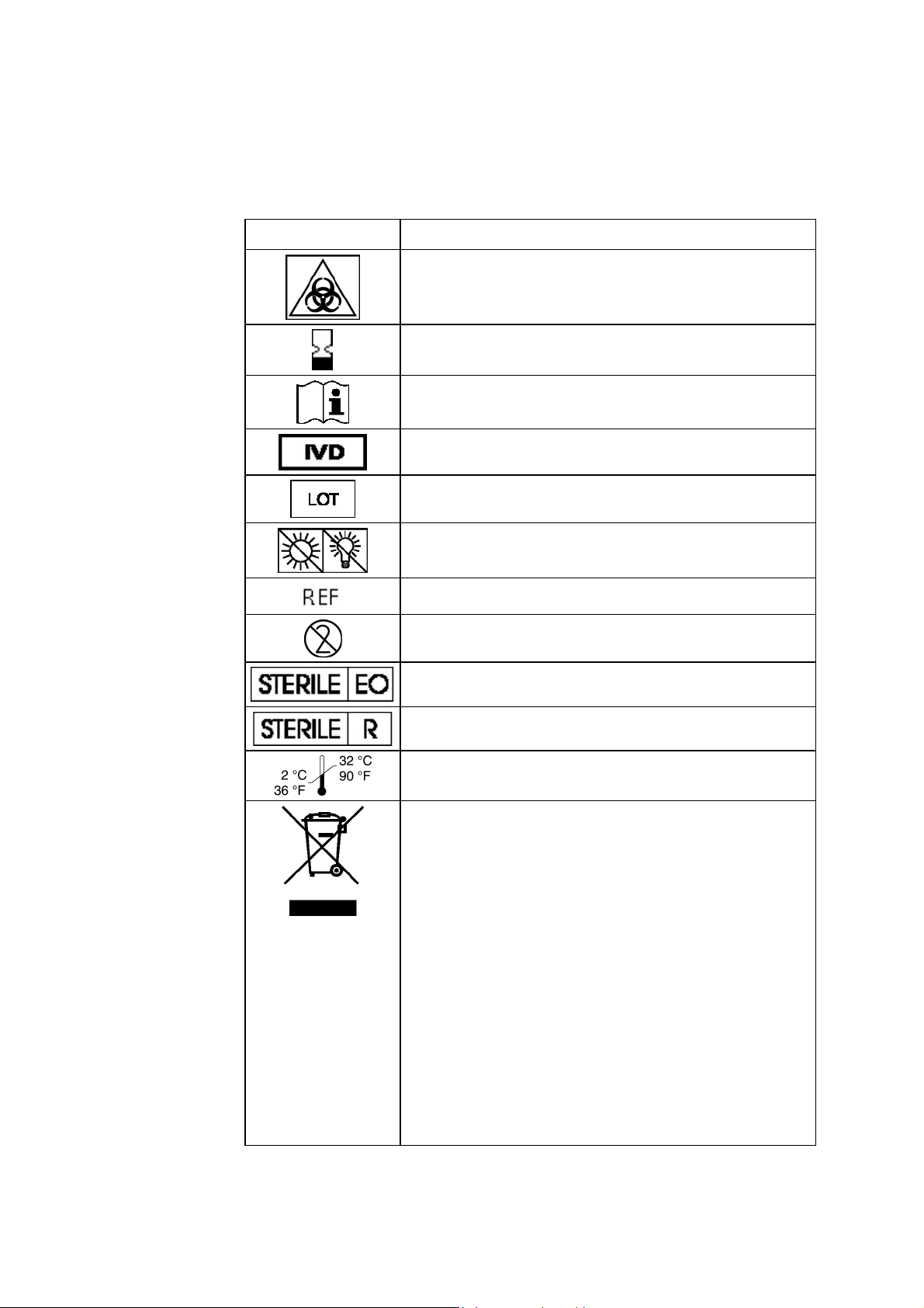
Symbols overview
List of symbols
The symbols below are used by Radiometer.
Symbol Explanation
Biohazard
Expiry date
See instructions for use
For In Vitro Diagnostic Use
Lot number
Sensitive to light. Store in a dark place.
Code number
For single use only
Sterilized by ethylene oxide
Sterilized by irradiation
Storage temperature from 2
°C to 32 °C (36 °F to 90 °F)
Waste of Electrical and Electronic Equipment (WEEE)
The symbol indicates that:
• Radiometer Medical ApS and its distributors
within the European Union (EU) and associated
states have taken the necessary steps to comply
with the directive, 2002/96/EC on waste electrical
and electronic equipment (WEEE).
• The instrument, when reaching its end of life,
must be collected and recycled separately from
other waste according to national requirements.
Please contact your local Radiometer distributor
for instructions.
1-8
Environmental implications:
WEEE contains materials that are potentially hazardous to
the environment and to human health.
Page 27

Overview
Introduction
Contents
2. What is what
The ABL800 FLEX analyzer is a complete unit comprised of several different
modules each performing a specific function and controlled by comprehensive
software. The modules are collected into well-defined sections according to their
related function.
This chapter describes the basic parts of the ABL800 FLEX analyzer and its
software.
This chapter contains the following topics.
Analyzer - front................................................................................................ 2-2
Analyzer - rear ................................................................................................. 2-4
Measuring section ............................................................................................ 2-5
Inlet module ..................................................................................................... 2-7
FLEXQ module ................................................................................................ 2-8
Thermal printer ................................................................................................ -10 2
Communication ports....................................................................................... -11
Barcode reader ................................................................................................. -13
AutoCheck module........................................................................................... -14
Screen elements................................................................................................ -15
Menu structure ................................................................................................. -24
Analyzer status................................................................................................. -28
Online aid facilities.......................................................................................... -36
Sample counter................................................................................................. -39
2
2
2
2
2
2
2
2
Page 28
2. What Is what ABL800 FLEX Operator's Manual
A
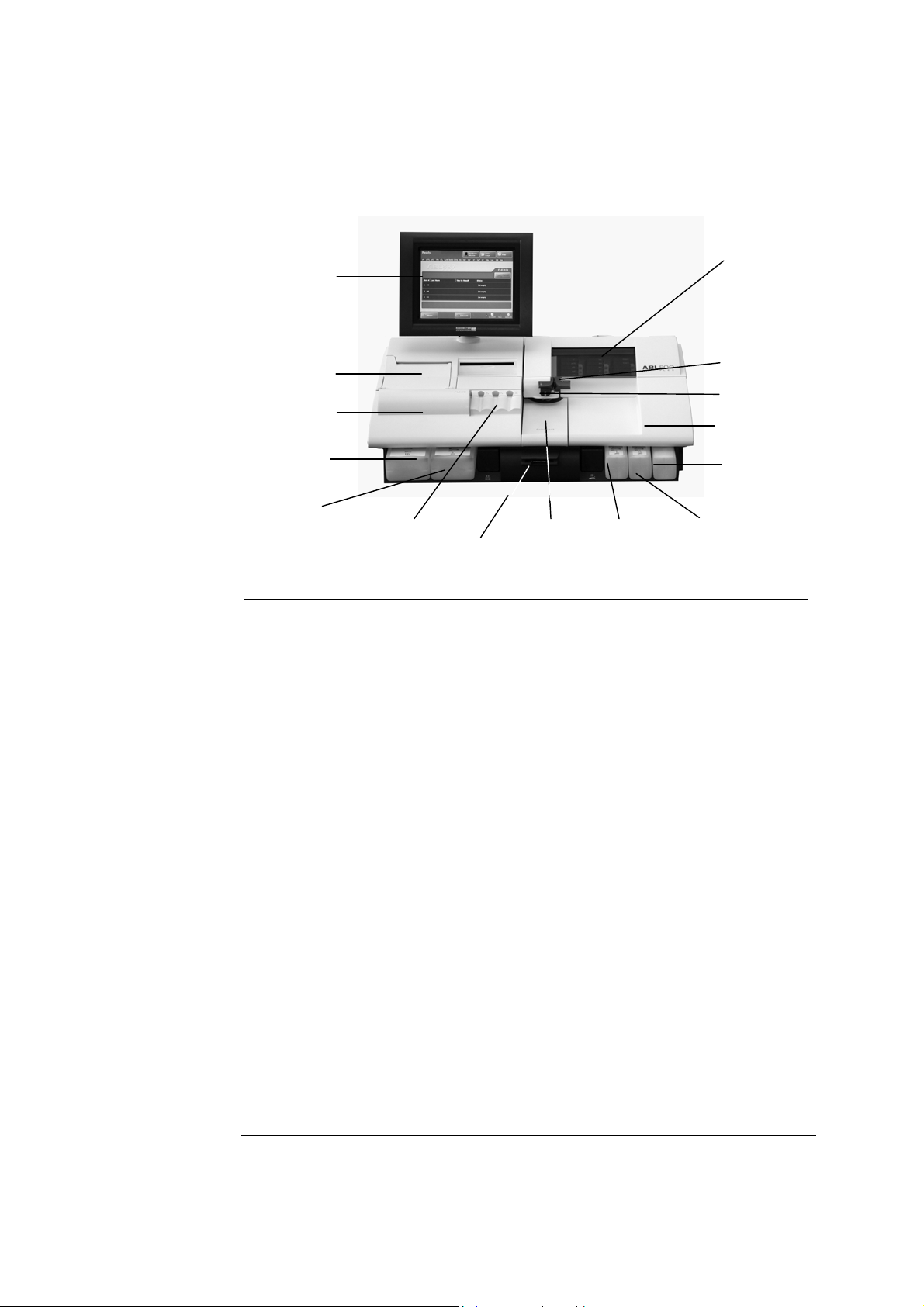
Analyzer - front
Parts and
functions
The components of the analyzer front (with covers) is shown below.
Touch screen
Cover with
window
Thermal printer
Left cover
Waste container
Capillary inlet
Syringe inlet
Right cover
Cleaning Solution
Rinse Solution
FLEXQ module
Barcode reader
utoCheck
module
Cal 1
solution
Cal 2
solution
Part Function
Color touch screen 10.4" LCD for operation and management of the
analyzer.
Thermal printer For automatic printout of data.
Left cover To access the waste container/Rinse Solution.
Waste container For waste collection. A sensor detects when container is
full, and a message is displayed on the screen.
Rinse Solution For rinsing the liquid transport system after various
analyzer activities.
2-2
FLEXQ module See FLEXQ module in this chapter.
Barcode reader See Barcode reader in this chapter.
AutoCheck module See AutoCheck module in this chapter.
Cal 1 Solution For performing 1- and 2-point calibrations.
Cal 2 Solution For performing 2-point calibrations.
Cleaning Solution For cleaning the liquid transport system of lipid deposits.
Right cover To access solutions and pumps – see overleaf.
Syringe inlet flap Lift to introduce syringe samples and quality control
solutions.
Capillary inlet flap Lift to introduce capillary samples.
Cover with window See Measuring Section in this chapter.
Continued on next page
Page 29
ABL800 FLEX Operator's Manual 2. What Is what
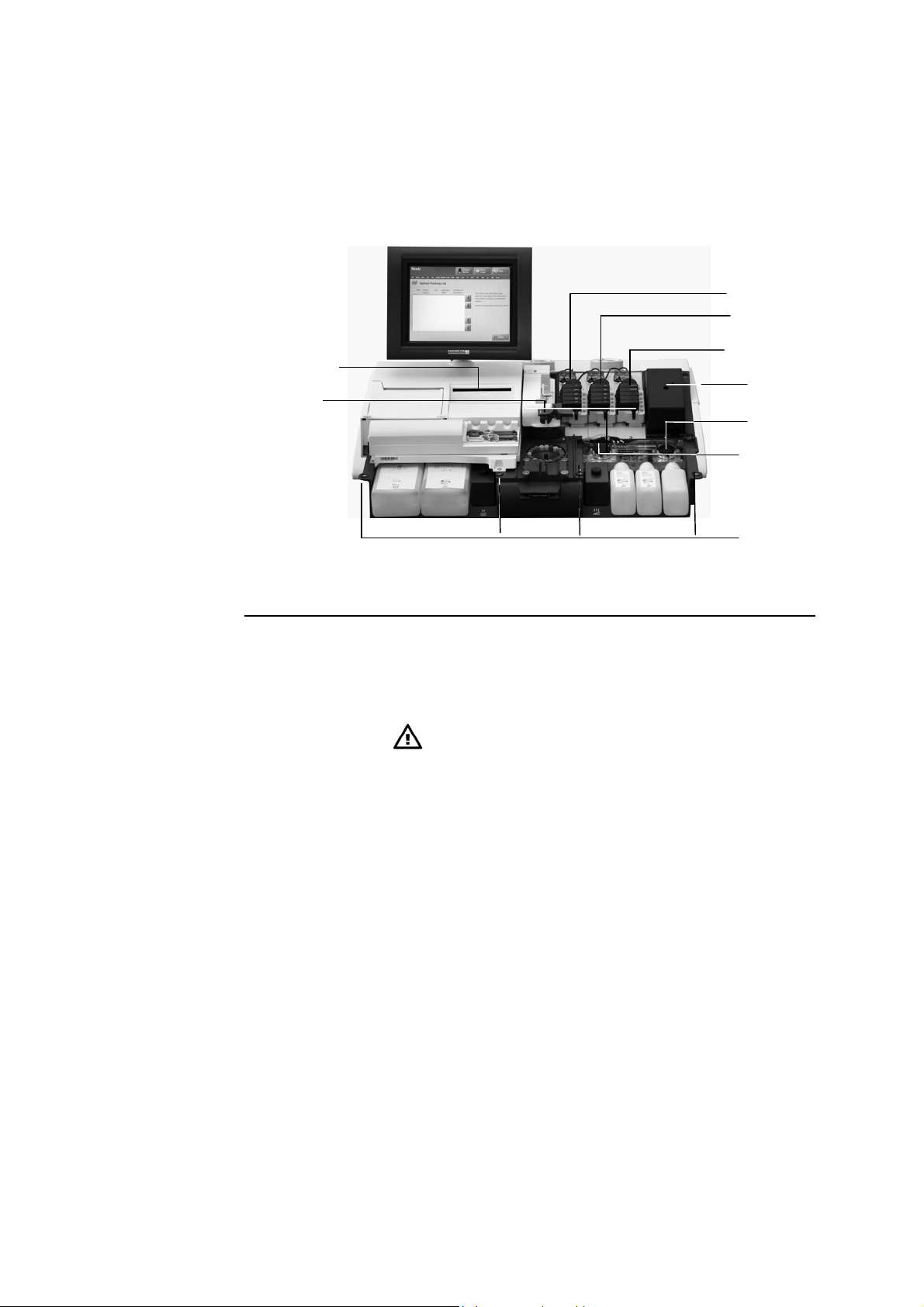
Analyzer - front, Continued
Parts and
functions
(continued)
The components of the analyzer front (without covers) is shown below.
pH/BG module
El/Met module
CD-ROM drive
Inlet module
Met II module
Oximetry module
Solution pump
Waste pump
Magnets
Part Function
Inlet module Accepts samples from a syringe/test tube or a capillary – see
Inlet Module in this chapter.
CD-ROM drive For storing data on a CD-RW disk or retrieving data from a
CD (e.g. installation software).
CAUTION – Installation of correct software
Install only software which is strictly intended for
use with the analyzer. Installation of other types may
affect analyzer performance.
pH/Blood Gas
(BG) module
Electrolyte/Metabolite (El/Met)
Measures pH, pO
component detail.
2+
Measures cCa
, cK+, cNa+, cGlu and cLac. See measuring
section detail.
, pCO2 and cCl–. See measuring
2
module
Met II module Measures creatinine.
(Only available for the ABL8x7 FLEX analyzers)
Oximetry (Oxi)
module
Measures ctHb, sO
FHbF and ctBil. See measuring component detail.
, FHHb, FO2Hb, FCOHb, FMetHb,
2
Solution pump Transports solutions through the liquid transport system.
Waste pump Transports liquid to the waste container.
Magnets Hold the covers in place.
2-3
Page 30
2. What Is what ABL800 FLEX Operator's Manual
r
r
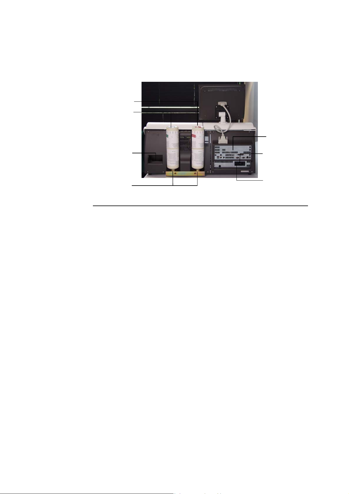
Analyzer - rear
Parts and
functions
The parts and components of the analyzer's rear panel are shown below.
Gas 1 cylinde
Gas 2 cylinde
Communication ports
Fan
Gas cylinder sockets
Power switch
Power socket
Part Function
Gas 1 cylinder Contains a gas mixture of 5.61 % CO
74.64 % N
.
2
, 19.76 % O2; balance
2
Gas 2 cylinder Contains a gas mixture of 11.22 % CO2, < 0.04 % O2;
balance > 88.74 % N
.
2
Fan For cooling internal components.
Gas cylinder
For mounting the gas cylinders.
socket
Communication
See section Communication Ports in this chapter.
ports
Power switch
For turning the analyzer on (position I) and off (position O).
Power socket For connecting the power cord.
In USA: If source is 120 V, use Radiometer cord 615-403
with parallel blade attachment plug.
If source is 240 V, use Radiometer cord 615-405
with tandem blade attachment plug.
2-4
Page 31

ABL800 FLEX Operator's Manual 2. What Is what
Measuring section
Parts and
functions
The modules and components of the measuring section are shown below.
Membrane valves
Electrode module
pumps
pH/BG module
Latch
Sample path
Membrane valves Control the flow of gas and solutions into the measuring
Electrode module
pumps
El/Met module
Met II module
Oximetry module
Part Function
modules.
Transport solutions and gas mixtures through the
measuring modules.
Latch Establishes electric contact between the electrode in the
measuring chamber and the electrode amplifier.
To access an electrode, push inwards on the upper
portion of the latch, and lift upwards.
Sample path Transports samples, solutions and gas mixtures.
pH/BG module Contains the measuring chamber with the pH, reference,
, pO2 and cCl
pCO
2
El/Met module Contains the measuring chamber with the cCa
+
cNa
, cGlu, and cLac electrodes (a filter is installed for
–
electrodes.
2+
, cK+,
the cGlu and cLac electrodes).
Met II module Contains the measuring chamber with the cCrea A and
cCrea B electrodes
(Only available for the ABL8x7 FLEX analyzers)
Oximetry module Contains the hemolyzer with glass cuvette, spectro-
photometer for measuring ctHb, sO
, FHHb, FO2Hb,
2
FCOHb, FMetHb, FHbF, ctBil on 128 wavelengths, and
the lamp unit.
Continued on next page
2-5
Page 32

2. What Is what ABL800 FLEX Operator's Manual
Measuring section, Continued
Electrode
locations
The electrodes are located in the electrode modules as follows:
-
cCl
electrode
cLac electrode
pCO2 electrode
electrode
pO
2
Reference electrode
pH electrode
The table below describes each electrode.
Module Electrode Type
cGlu electrode
+
cNa
electrode
cK+ electrode
cCa2+ electrode
cCrea A electrode
cCrea B electrode
2-6
pH/BG cCl– E744
pCO2 E788
pO2 E799
Reference E1001
pH E777
El/Met cLac E7077
cGlu E7066
cNa+ E755
cK+ E722
cCa2+ E733
Met II cCrea A E8088
cCrea B E8089
NOTICE: An orange filter is placed in the measuring chambers for the cGlu,
cLac, cCrea A and B electrodes.
Page 33

ABL800 FLEX Operator's Manual 2. What Is what
Inlet module
Parts and
functions
The inlet module accepts samples from a syringe/test tube or a capillary (the
syringe and capillary inlet flaps are removed on the picture). Syringe and capillary
inlet flaps are interlocked so that only one may be opened at a time.
Probe
attachment
Preheater
Inlet probe
Capillary inlet flap post
Syringe inlet flap post
Capillary inlet
Syringe inlet
Inlet gasket
unit
Part Function
Probe attachment Secures inlet probe. Open the clip to remove probe.
Preheater
Heats all samples and gases to 37 °C.
Inlet probe Automatically moves into the syringe to aspirate the
required sample.
Capillary inlet flap post Holds the inlet flap for capillary samples.
Syringe inlet flap post Holds the inlet flap for syringe samples.
Capillary inlet Receives sample from a capillary.
Syringe inlet Receives sample from a syringe and test tube.
Inlet gasket unit Provides transfer of samples from a sampling device
to the inlet probe; can be removed.
2-7
Page 34

2. What Is what ABL800 FLEX Operator's Manual
FLEXQ module
Parts and
functions
FLEXQ module for automatic transport of samplers to the inlet is shown below.
FLEXQ position before or after analysis:
Barcode reader
Samplers
Sampler tray
FLEXQ position during analysis:
Indicator
diodes
2-8
Continued on next page
Page 35

ABL800 FLEX Operator's Manual 2. What Is what
FLEXQ module, Continued
Parts and
functions
(continued)
The components are as follows:
Part Function
FLEXQ sampler tray FLEXQ sampler tray moves to the position for
measurement by means of a step motor (not
shown).
The samplers used in the sampler tray should be
safePICO sampler with the safeTIPCAP.
Indicator diodes Change the color from green to yellow when the
optical switch detects the sampler placed in the
slot.
Barcode reader Laser barcode reader reads the sampler barcode. A
short beep indicates that the barcode has been
read. You can scan the Sampler ID on the
analyzer’s scanner and then place it in the sample
tray or you can place the sampler in the sampler
tray and let the FLEXQ scanner read the sampler
barcode.
Sampler tray cover
Mixer tray
The sampler tray cover has three slots for the
samplers; the slots have optical switches for
detecting the sampler. The cover can be removed
(as shown) for cleaning.
The mixer rotates and moves the ball in the
sampler in order to mix the blood sample. The
sample is adequately mixed after 7 seconds.
The mixer tray moves into position under the
sampler immediately before the measurement.
2-9
Page 36

2. What Is what ABL800 FLEX Operator's Manual
r
r
Thermal printer
Parts and
functions
The components of the thermal printer (with the cover open) are shown below.
Release lever
Drive rolle
Paper roll holder
Cove
Paper guide
Part Function
Release lever Push the lever fully back to lift the drive roller from the
printer head and paper guide in order to adjust paper
alignment.
Remember to return the lever to its original position (as
shown) in order to print.
Drive roller Feeds the thermal paper through the printer.
Paper guide Located behind the drive roller, it is between this and the
drive roller that paper is fed.
Paper roll holder Holds the paper roll in place.
Cover Open to replace the paper roll. Contains instructions on
how to make a replacement.
Close the cover when a new paper roll has been mounted
in the printer.
2-10
Page 37

ABL800 FLEX Operator's Manual 2. What Is what
Communication ports
Ports and
functions
The following communication ports are available:
USB ports (two)
Mouse
Keyboard
Fuse for printer
unit
Display unit
The functions of the communication ports are as follows:
Port Function
Display unit port For connection to the analyzer’s display
Mouse port PS/2 connector used for the connection of a standard
mouse (user supplied).
Printer port
Network connector
Ext. VGA monitor
Serial port (COM2)
Main fuse
Keyboard port PS/2 connector used for connection of a keyboard (user
supplied).
Serial port
(COM2)
9-pin serial port used for HIS/LIS communication or
connection of an external barcode reader.
Network RJ45 ethernet interface connection to network.
Printer port Parallel port for connection to a local printer
Continued on next page
2-11
Page 38

2. What Is what ABL800 FLEX Operator's Manual
Communication ports, Continued
Ports and
functions
(continued)
Port Function
External VGA
monitor port
15-pin connector for external monitor (optional; is enabled
by Radiometer service representative).
USB (2 ports) For connecting USB devices, e.g. a removable drive.
USB keyboard supported. Other USB devices need an
approved XP driver (user-supplied mouse or modem, etc.).
Fuse for printer
unit
The compartment contains 1 protective fuse: 5 × 20 mm, 4
Amp, Slow blow (T4AL) (order code number 450-035).
Main fuse The compartment contains 2 protective fuses: 5 × 20 mm,
4 Amp, High break (T4AH). Type Shurter No. 0001.2510
(order code number 450-144).
WARNING – Risk of fire
Fire hazard. Replace fuse as marked.
2-12
Page 39

ABL800 FLEX Operator's Manual 2. What Is what
Barcode reader
Barcoded items
The following items have barcodes that can be read into the analyzer:
Item Location of barcode
All solution containers Label on the container
QC ampoules Insert in the box containing the ampoules
tHb calibration ampoules Insert in the box containing the ampoules
Electrodes Label on the box containing the electrode
Electrode membranes Label on the box containing the membrane unit
Gas cylinders Label on the cylinder
Pump tubing Label on the tubing packaging
Fan filter Label on the box containing the filter
Inlet gasket Label on the box containing the inlet gasket
Reading in a
barcode
In addition to the items above, you can enable every text box on the Patient
Profile, Patient ID, Patient Result, QC ID and Recording Fluid Replacement
screens where it is possible to enter a barcode – refer to Miscellaneous Setup in
chapter 3: Installation and setup.
Hold the barcode of the item you wish to read in parallel to the sensor part of the
barcode reader. A short beep from the barcode reader indicates that the information
has been read in successfully.
Sensor part
2-13
Page 40

2. What Is what ABL800 FLEX Operator's Manual
A
AutoCheck module
Parts and
functions
The AutoCheck module is shown below.
utoCheck carousel
To close
To open
Retractable cover
Part Function
Retractable cover Gives access to the carousel.
You can either slide the carousel cover open or press
Menu - Analyzer Status - AutoCheck - More - Open
Module.
Make sure that no objects prevent the cover from
opening freely.
AutoCheck carousel Contains the AutoCheck ampoules packed according to
the optimal packing list – see Refilling the AutoCheck
carousel in chapter 7: Replacements.
2-14
Page 41

ABL800 FLEX Operator's Manual 2. What Is what
Screen elements
Ready screen
Operation and management of the ABL800 FLEX analyzers is performed via a
touch screen. Almost all commands to the analyzer come from the touch of a
button or area on the screen.
The touch screen is divided into three sections:
Top section
Center section
Top section
Bottom section
For the analyzers without the FLEXQ module, the Ready screen looks as follows:
The Ready screen appears automatically if the touch screen remains idle for more
than 3 minutes. The screen intensity reduces by 50 % when the analyzer is not
used.
The status bar varies slightly, according to which screen you are in and the status
of the analyzer.
Example:
The status describes the current task of the analyzer (e.g. calibration, measurement,
etc.) or its status (e.g. ready for use, on hold, etc.).
Continued on next page
2-15
Page 42

2. What Is what ABL800 FLEX Operator's Manual
Screen elements, Continued
Top section
(continued)
The time bar is present only when the analyzer is performing a task; it follows the
progress of the current task. For example:
The Stop button
is visible only when it is allowed to interrupt an activity
in progress.
The parameter bar lists all measured parameters available and activated on your
analyzer.
It allows you to judge the parameter status at a glance before you have to perform a
measurement.
Green parameter:
Parameter status is okay; no problem is detected on the given
measuring channel.
Yellow
parameter:
Error associated with the given parameter during last
calibration or quality control measurement. The parameter is
unreliable and will have “?” (if requested in Corrective
Red parameter:
Actions) in front of the result.
Serious error associated with the given measuring channel.
Parameter cannot be used at all and will be displayed as
“…..”; or a parameter was repressed in the Parameter Setup
program due to errors during last calibration or quality
control measurement.
NOTICE: A parameter disabled in the Parameter Setup program will be removed
from the parameter bar – see Analysis Setup Programs (Disabled versus
Deselected Parameters) in chapter 3.
2-16
Continued on next page
Page 43

ABL800 FLEX Operator's Manual 2. What Is what
Screen elements, Continued
Center section
The center section is the main information and interaction area of which there are
many different types.
The center section of the Ready screen is described part by part, starting from the
top (for the analyzers without FLEXQ module the center part contains the analyzer
type and – if entered in Miscellaneous Setup (see chapter 3) – analyzer message).
This part of the Ready screen contains the following elements:
• Analyzer name
• The messages to the operator regarding the FLEXQ activities
• Urgent Manual Sample request button. The button allows you to book an inlet
for an urgent measurement while the analyzer performs a task.
The button is grayed out when the analyzer is ready for any measurement.
This part of the Ready screen contains the following elements:
• "Slot #": condition of each sampler tray slot (1, 2 and 3) is indicated with the
arrows that reflect the indicator diodes in the sampler tray:
Green Place the sampler into the slot
or remove it from the slot.
Blinking
green
Wait for the sampler to be
identified.
Yellow Do not remove the
sampler from the slot.
Blinking
yellow
Remove the sampler
from the slot.
• "Sampler ID": appears when the sampler is placed in the sampler tray slot and is
registered. The name of this column can be changed in the Sample Logistics
Setup (see Analysis Setup in chapter 3 of this manual).
• "Time to Result": shows time left till a result will be ready; the clock indicates
that the sample age has exceeded settings selected in Sample Logistics setup.
• "Status": gives information about a sampler in the slot:
Slot empty A slot is ready to accept a sampler.
Ready for processing Sampler has been registered in the slot.
Processing Patient and sampler data are being processed.
Completed Measurement is completed and the result can be
viewed.
Continued on next page
2-17
Page 44

2. What Is what ABL800 FLEX Operator's Manual
Screen elements, Continued
Center section
(continued)
Patient data can be edited.
Result can be viewed.
This part of the Ready screen is reserved for the analyzer messages and is entered
in the Miscellaneous Setup (see chapter 3 in this manual):
Other screen types and their elements are described on the following pages.
Icon and screen name identify each screen. Example:
Icon
Screen name
2-18
The icon and title of a screen are the same as the button that gives access to that
screen.
Continued on next page
Page 45

ABL800 FLEX Operator's Manual 2. What Is what
Screen elements, Continued
Center section
(continued)
Text boxes show a text in the form of
lists, items, tables, etc. Various types
of text boxes and navigation in them
are given on the next page.
The first line is highlighted. To
highlight another line, touch it on the
screen or use up and down arrow scroll
keys displayed on the screen beside a
relevant text box.
A scroll bar scrolls a text box
horizontally when the text box extends
beyond the area available on the
screen.
A single-arrow scroll button
highlights one item at a time upward or
downward.
Scroll bar
Scroll keys
A double-arrow scroll button
highlights an item at the top or the
bottom of the screen.
The first line is highlighted. To
highlight another line, use the up and
down arrow buttons or touch this line
in the box.
Enter the data using the screen keypad
or keyboard.
In this text box you can select one of
the predefined options.
Use the up and down arrow buttons to
select an item.
NOTICE: If the text box already
contains an entry, it will be overwritten
and cannot be retrieved.
Text boxes are designated in quotation marks, e.g. "Operator". The same applies to
the other elements on the center section of the screen: names of the columns (e.g.
"Status"), input fields (e.g. "Draw time"), etc.
Continued on next page
2-19
Page 46

2. What Is what ABL800 FLEX Operator's Manual
N
Screen elements, Continued
Center section
(continued)
Check buttons allow you to enable/disable or select/deselect an item on the
screen. For example:
A function is selected (e.g.
acoustic signal if the inlet
remains open) or activated (e.g.
communication with the
Parameter is
selected.
RADIANCE system)
A function is deselected or
deactivated.
Parameter is
deselected.
Screen keypad allows the entry of numerical data on the screen.
umerical keys
from 0 to 9.
Decimal point.
The buttons listed below have the following functions:
Press to confirm a numerical entry and to highlight the
next line in the text box.
Press to delete a character (from right to left) or to type in
the new data (the box is cleared as soon as the first
character is typed).
Press to display the full alphanumerical keyboard.
Continued on next page
2-20
Page 47

ABL800 FLEX Operator's Manual 2. What Is what
A
Screen elements, Continued
Center section
(continued)
Screen keyboard is used for entering both alphabetical and numerical data − see
the description on the next page.
ctivated text box
The keyboard functions as a normal keyboard with alphabetical and numerical
characters. The typed text appears in the activated text box.
Enter
Press to confirm the entry and to return to the previous screen.
Backspace
Press to delete characters from right to left.
Press to cancel any changes made in the activated text box and
to return to the previous screen
Press to delete an entry in the activated text box.
Shift
Press to type a capital letter or symbol.
Press to lock the keyboard in order to type capital letters and
symbols on the numerical keys. When activated, indicator is
green.
Up/down/left/right arrows move the cursor in the activated text
box in order to edit a text.
Continued on next page
2-21
Page 48

2. What Is what ABL800 FLEX Operator's Manual
Screen elements, Continued
Buttons
Each button has an icon and a name placed on it. When pressed, it opens a screen
or a menu.
Information bar
and icons
The buttons are designated in bold italics in this manual, e.g. Menu, Utilities, etc.
The buttons displayed in full color can be activated. A button in a weaker color,
i.e. grayed-out, is temporarily inactive.
The buttons at the top and the bottom of the screen can be selected in the Setup
program Access Profiles (in the Analyzer Security menu) together with the access
profiles for each operator – for detailed information see the description in chapter
3: Installation and setup.
Note the functions of the following buttons:
Returns you to the previous screen in the same program,
e.g. in the Patient Results log, it will return you from the
Patient Identification screen to the Patient Result
screen.
Returns you to the Ready screen.
The information bar is placed in the lower right corner of the screen.
2-22
Continued on next page
Page 49

ABL800 FLEX Operator's Manual 2. What Is what
Screen elements, Continued
Information bar
and icons
(continued)
The following icons are available on the information bar:
Icon Function
Shows the current time in the selected format.
Shows that an analyzer is connected to the RADIANCE
system.
Shows that an analyzer is connected to the QA Portal.
Shows the time of the next scheduled calibration. The time
changes when a calibration has been completed.
Shows the time of the next scheduled QC measurement.
The time changes when a QC measurement has been
completed.
Shows that the remote operator is connected.
Click to make more icons visible.
Click to reduce the number of visible icons to a clock.
2-23
Page 50

2. What Is what ABL800 FLEX Operator's Manual
Menu structure
Menu at
analyzer startup
When the analyzer is taken into use, only the following limited menu is available:
Press Menu.
Calibration Progs:
1 Point Calibration
2 Point Calibration
Auxiliary Progs:
Rinse
Cleaning
Protein Removal
Decontamination
AutoCheck Programs
Run High Crea Check
(only the ABL8x7 analyzers)
Log on
Analyzer Status Help
Start Progs
Utilities
Standby
Temporary Shutdown
Last patient result
Tutorials
Data Logs
Patient Results Log
Patient Profile Log
QC Log
Calibration Log
Activity Log
Allowed actions
at analyzer
startup
2-24
The following actions are allowed at analyzer startup:
To perform a measurement
•
To call a calibration
•
To edit data in the data logs
•
To perform a replacement
•
To start an AutoCheck measurement
•
The menu above and the scope of actions are suitable for those users whose
activities include performing measurements and occasional replacements.
Continued on next page
Page 51

ABL800 FLEX Operator's Manual 2. What Is what
Menu structure, Continued
Entering
standard
password
To access the complete menu, do the following:
Step Action
Press Menu on the Ready screen.
1.
Then click on Logon.
Type in the standard password: 123456.
2.
Standard password:
123456.
See chapter 3: Installation and setup, Analyzer Security, in this
manual for further information about the logon possibilities.
Confirm with Enter.
Press Menu to access the complete menu – see the next section.
3.
The access possibilities for each user of the analyzer and their passwords are
entered in Setup program Access Profiles – see chapter 3: Installation and setup in
this manual.
Continued on next page
2-25
Page 52

2. What Is what ABL800 FLEX Operator's Manual
Menu structure, Continued
Complete menu
Press Menu.
My results*
Last patient result
Calibration Progs:
1 Point Calibration
2 Point Calibration
tHb Calibration
Auxiliary Progs:
Rinse
Cleaning
Protein Removal
Decontamination
Liquid Sensor Adjust
Pump Calibration
Tubing Refill
AutoCheck
Programs
Run High Crea
Check
(only the ABL8x7
analyzers)
Log on
Analyzer Status
Start Progs
Disk Functions:
WDC Report
Back up All Data
Restore All Data
Export Data Logs
Import/Export Archives
Save Setup
Load Setup
Restore Default Setup
Eject CD
Utilities
Help
Tutorials
Data Logs
Standby
Sample Counter
Temporary
Shutdown
Long-term
Shutdown
RADIANCE Browser
(optional)
Patient Results Log
Patient Profile Log
QC Log
Calibration Log
Activity Log
Archived Data Logs
Patient Report
Archive
Quality Control
Archive
Calibration
Archive
Activity Archive
2-26
Setup:
Analysis Setup
QC Setup
Calibration Setup
Replacement Setup
General Setup
Analyzer Security
Print Setup
* Is selected in the Setup program Access Profiles (in the Analyzer Security menu)
– see chapter 3.
Structure of the Setup programs – see chapter 3: Installation and Setup.
Continued on next page
Page 53

ABL800 FLEX Operator's Manual 2. What Is what
Menu structure, Continued
Access to
analyzer menu
The access to various parts/functions of the analyzer menu is determined by the
rights defined in the Setup program Access Profiles (in the Analyzer Security
menu).
Example:
You as a user can enter the following: Rinse, Patient Report and QC logs, and
Standby programs. Then your menu – after you have logged on – will look like
this:
Log on
Last patient result
Analyzer Status
Help
Start Progs
Data Logs
Rinse
Utilities
Patient Report Log
QC log
Standby
For details see the chapter 3: Installation and setup and chapter 15: Radiometer
Settings.
2-27
Page 54

2. What Is what ABL800 FLEX Operator's Manual
A
Analyzer status
Analyzer status
at a glance
The working condition of the analyzer is continuously monitored during its
operation.
To evaluate the analyzer status at a glance before a measurement, use the following
facilities:
• parameter bar
• color of the traffic light on the Analyzer Status button.
Analyzer Status
elements
nalyzer Status button
Red = cannot be used; Yellow = unreliable; Green = OK
To enter the Analyzer Status screen, press Menu - Analyzer Status.
Traffic light color of the Analyzer Status button is determined by the traffic light
colors of the following status elements:
Status element The colors indicate…
G
Calibration Status
REEN – OK.
Y
ELLOW – error(s) in the last calibration and/or cal
schedule reminders.
RED – error-prone parameters are repressed.
Continued on next page
2-28
Page 55

ABL800 FLEX Operator's Manual 2. What Is what
Analyzer status, Continued
Analyzer Status
elements
(continued)
Button The colors indicate…
Quality Control
Status
G
REEN – OK.
Y
ELLOW – error(s) in the last QC measurement and/or
QC schedule reminders.
Calibrations
status
Reagents
Status
RED – error-prone parameters are repressed.
G
REEN – no replacements due at the present time.
Y
ELLOW – a replacement is due, Calibration/Cleaning
solutions expire soon or Calibration/Cleaning
solutions have expired.
G
Electrode and
others
System Messages
REEN – no replacements due at the present time.
Y
ELLOW – a replacement is due.
G
REEN – no (critical) messages.
Y
ELLOW – non-critical messages.
R
ED – critical messages. The analyzer cannot
calibrate or measure.
G
AutoCheck
Status
REEN – no replacements due at the present time.
Y
ELLOW – a replacement is due.
The Calibrations status gives an overview of the status of the most recently
performed calibration of each type and relevant messages.
The following information is available on the screen:
Calibration Type Lists each calibration type along with its status:
OK
?
Calibration was accepted.
Error(s) detected during calibration.
Pending or overdue calibration. The last
calibration was accepted.
Continued on next page
2-29
Page 56

2. What Is what ABL800 FLEX Operator's Manual
Analyzer status, Continued
Calibration
status
(continued)
Calibration Type Lists each calibration type along with its status:
?+
Pending or overdue calibration. The last
calibration was not accepted.
Last Time The date and time the last calibration of the specified type
was performed.
Next Time The date and time the next calibration of the specified
type is due according to the Calibration Schedule - see
Calibration Schedule, chapter 3.
Interval The time interval between calibrations as set up in the
Calibration Schedule.
The following buttons are available:
During a
calibration:
Result
Electrode Upd.
After a
calibration:
Result
Press to display the result of the highlighted calibration.
Press to display the electrode updatings for the ongoing
calibration.
Press to display the result of the highlighted calibration.
2-30
Start
Calibration
Is activated for the overdue calibrations or the calibrations
with "?".
Continued on next page
Page 57

ABL800 FLEX Operator's Manual 2. What Is what
Analyzer status, Continued
Quality Control
status
The Quality Control status provides the following information:
status of the last measurement on each control solution type
•
messages referring to quality control measurements.
•
For the ABL8x7 FLEX analyzers, please note that Slot 11 will be automatically
installed when you scan the barcode for the Cleaning Met II Solution during
replacement.
Element Function
Solution Lists the quality control slot and its solution type along
with a status symbol.
Cleaning Met II Solution (for ABL8x7 FLEX analyzers
only) is used for quality control of high creatinine levels.
OK
?
The last measurement was accepted.
One or more of the following occurred:
• error in the last calibration.
• analyzer error during last QC measurement.
• a parameter measurement is outside the defined
ranges or a Westgard Rule has been violated.
?
The next measurement is overdue, and the
previous measurement, if any, was accepted.
The last quality control measurement had errors
present, and the next measurement is overdue.
Lot The solution lot number for the slot.
Last Time Lists the time the last measurement was performed.
Next Time Lists the next scheduled time to perform the measurement
on the slot. See Quality Control Schedule, chapter 3.
Continued on next page
2-31
Page 58

2. What Is what ABL800 FLEX Operator's Manual
Analyzer status, Continued
Quality Control
status
(continued)
Buttons:
Run AC
ampoule
Press to start a measurement on the highlighted AutoCheck
solution.
For ABL8x7 FLEX analyzers only: When Slot 11 is
highlighted, this button changes to Run High Crea Check to
start a measurement on the Cleaning Met II Solution.
Reagents status
Result
Press to display the last measurement result on the control
solution.
The Reagents status shows the following:
status of the solutions and gas cylinders
•
When Calibration/Cleaning solutions are expired, the container in question
is marked with a clock above it and the contents are colored orange.
messages referring to solutions and gas cylinders.
•
2-32
Buttons:
Replace
Press to enter the screen for replacements of fluids – see
chapter 7: Replacements.
Adjust Level
Press to enter the Solution Level Adjustment program to make
adjustments – see chapter 3 in this manual.
Troubleshoot
Press to view the error interpretation and operator actions –
see the description in chapter 11: Troubleshooting.
Close
Press to exit to the Ready screen.
NOTICE: The Calibration and Cleaning Met II Solution containers are filled so
that they provide up to 14-days of use in the ABL8x7 FLEX analyzer. This will be
registered on the screen by percentages that are lower than 100 % (i.e. 87%, 75%,
50% for the Calibration Solution 1, Calibration Solution 2 and Cleaning Met II
Solution, respectively). This has been made so that the solution warning function
will not be impaired and you can select the warning values in the usual manner.
Continued on next page
Page 59

ABL800 FLEX Operator's Manual 2. What Is what
Analyzer status, Continued
Electrodes and
Other status
The Electrodes and Other status shows the following:
replacement schedule for items replaced in the Hold mode
•
messages referring to replacements or user activities.
•
System messages
AutoCheck
status
Buttons:
Replace
Highlight the item and press this button to enter the screen for
replacements of electrodes/membranes – see Replacing
membrane or electrode in chapter 7.
Log Activity
Activate “User Activities” part of the screen to make this
button visible. When the button is visible, press it to enter the
User Activity program to edit the user activities list – see
chapter 3 in this manual.
Close
Press to exit to the Ready screen.
See chapter 11: Troubleshooting.
AutoCheck Status is available only if the AutoCheck module has been installed. It
shows the following:
status of the carousel and the measurements scheduled in the QC Schedule
•
program (see section Quality control setup in chapter 3).
Messages referring to AutoCheck.
•
Continued on next page
2-33
Page 60

2. What Is what ABL800 FLEX Operator's Manual
Analyzer status, Continued
AutoCheck
status
(continued)
Element Function
Next Scheduled To show the next AutoCheck solution/lot combination
according to the scheduled setup.
Next Replacement To show the date and time for refilling the carousel
according to the scheduled setup.
Available To show the presently available AutoCheck control
solutions: type, lot and quantity of ampoules in the
carousel.
Use the up/down arrow buttons to highlight the desired
solution.
Continued on next page
2-34
Page 61

ABL800 FLEX Operator's Manual 2. What Is what
Analyzer status, Continued
AutoCheck
status
(continued)
The carousel shows the number of ampoules available in it. The black spots
indicate used ampoules.
Button
Packing List
Reset
Open Module
AutoCheck
Programs
unrolls to access the following buttons:
Displays the Optimal Packing List screen.
Cancels any pending quality control measurements.
•
Interrupts ampoule conditioning in the carousel.
•
Resets wet section programs.
•
Opens the cover of the AutoCheck module.
Displays the AutoCheck Programs screen to start an
AutoCheck measurement.
2-35
Page 62

2. What Is what ABL800 FLEX Operator's Manual
Online aid facilities
Online facilities
Help
The online aid facilities include the following:
• Online Help
• Tutorials
• Online troubleshooting (see chapter 11 in this manual).
This function assists you in using the analyzer.
Press the button in the Main menu (if not moved to the
Ready screen – see Access Profiles (in the Analyzer
Security menu) in chapter 3) or on the Ready screen.
The help text is available for practically every screen your analyzer shows during
its operation.
The Contents screen displays all
help topics. Each topic is hyperlinked to either the next topic level
or to the appropriate help text
screen.
Use the scroll bar or touch the text
to search through the topics and
access the relevant help
information.
Press the Previous Topic button to
display the help text of a previous
screen.
The Index screen is an alphabetic
list of subjects in the help program.
Each letter at the top of the screen
is a hyperlink to that section in the
index.
Touch the letter to display the list
of entries under that letter.
Each index entry is displayed in
bold, purple text (a hyperlink).
Simply touch the text to display the
relevant help text.
Continued on next page
2-36
Page 63

ABL800 FLEX Operator's Manual 2. What Is what
Online aid facilities, Continued
Tutorials
Tutorials are short video sequences of commonly used procedures. Press the
button in the main menu or button next to the
Troubleshooting button (when performing troubleshooting) to enter the Tutorial
Playlist screen.
The Preview shows the highlighted sequence animation. To start a tutorial on full
screen, highlight the topic of interest from the menu, using the arrows, and press
the Play button.
Topic Contents
Blood Samples Videos of a capillary, syringe or expired air sample
introduction by highlighting it.
Quality Check Videos of manual or AutoCheck quality control.
Replacement Video sequences on various replacements.
The buttons on the Tutorial screen during a sequence allow to do the following:
Continued on next page
2-37
Page 64

2. What Is what ABL800 FLEX Operator's Manual
Online aid facilities, Continued
Tutorials
(continued)
Button Function
Play.
Pause.
Stop.
Show previous picture – show next picture.
Switch on the sound (voice presentation of a sequence) with
volume regulation.
Switch off the sound.
Show the list of video sequences.
The "-" button puts Tutorials in the background in order to
perform an action and then to return to Tutorials again.
The "x" button exits Tutorials.
When a button is grayed out, it is not functional.
2-38
Page 65

ABL800 FLEX Operator's Manual 2. What Is what
Sample counter
Purpose
Description
The sample counter allows you to keep track of the measurements, calibrations and
quality control.
The screen elements are described below:
Element Function
Parameter
Count
Lists the parameters and how many times each of them was
measured by the analyzer. Normally the count is the same as
the total number of measurements provided the parameters
were not excluded from the measurement(s).
Counters Shows the number of sample measurements, calibrations and
QC measurements made since the sample counter was last
reset (User column). The following is registered:
Activity Number of...
Total Completed sample/quality control measurements/
calibrations only. Interrupted or aborted
measurements are excluded.
Aborted Aborted sample/quality control measurements/
calibrations due to sample errors, wet section
errors, etc. interrupted measurements excluded.
User All completed sample/quality control
measurements/calibrations performed by all
operators since the sample counter was last reset.
User counters
last reset
Gives the date when the counters in the User column were last
reset to zero.
Continued on next page
2-39
Page 66

2. What Is what ABL800 FLEX Operator's Manual
Sample counter, Continued
Description
(continued)
Element Function
Reset Counters
For the analyzers with no logon protection of the Setup
programs, press this button to reset the counters in the User
column.
Print
Close
Press to start the printout of information in Counters and in
Parameters.
Press to return to the Ready screen.
2-40
Page 67

Overview
Introduction
Contents
3. Installation and setup
After the analyzer has been installed, you can define the settings on your ABL800
FLEX analyzer according to your own needs and requirements.
This chapter contains the following topics.
Installation........................................................................................................ 3-2
Setup menu structure........................................................................................ 3-3
Analyzer security ............................................................................................. 3-6
Analysis setup .................................................................................................. 3-13
Patient reports .................................................................................................. 3-26
Calibration setup .............................................................................................. 3-32
Quality control setup........................................................................................ 3-35
Replacement setup ........................................................................................... 3-48
Parameters and input setup............................................................................... 3-55
Analyzer settings.............................................................................................. 3-62
Communications .............................................................................................. 3-68
Printers............................................................................................................. 3-77
Disk Functions setup........................................................................................ 3-80
Corrective actions ............................................................................................ 3-83
Miscellaneous setup......................................................................................... 3-86
Page 68

3. Installation and setup ABL800 FLEX Operator's Manual
Installation
Information
The ABL800 FLEX analyzers are installed and fully prepared for use by
Radiometer representatives in your country. The reason for it is that − due to the
analyzer's modular design − each user can select only those modules that cover
his/her specific needs. These modules are installed and checked at the user's place.
Installation of consumables and accessories are exactly the same as the procedures
described in chapter 7: Replacements.
3-2
Page 69

ABL800 FLEX Operator's Manual 3. Installation and setup
Setup menu structure
Accessing Setup
programs
To access the Setup programs, press the buttons:
−
Setup menu
structure
Setup
Analyzer Security:
General Security
Operators and Passwords
Access Profiles
Replacement Setup:
Replacement Schedule
User Activities
Solution Level Forecast
Solution Warning
Expiration Warning
AutoCheck Warning
Calibration Setup:
Cal Schedule
Drift Tolerances
Print Setup
QC Setup:
QC Solutions
QC Schedule
QC Ranges
QC Input Setup
QC Statistics
Westgard Rules
Rilibäk Ranges
Analysis Setup:
Capillary Modes
Syringe Modes
Patient Reports
Reportable Ranges
Reference Ranges
Sample Pre-registration
Sample Logistics Setup
General Setup
See the next page
Continued on next page
3-3
Page 70

3. Installation and setup ABL800 FLEX Operator's Manual
Setup menu structure, Continued
Setup menu
structure
(continued)
Printers:
Printer Setup
Automatic Printing
Analyzer Settings:
Analyzer ID
Time/Date
Acoustic Signal
Environment
Language
General Setup
Communications:
RADIANCE Connection
LIS/HIS Connection
QA Portal
Automatic Data Transmission
Automatic Data Request
Patient Lookup Setup
Remote Support
Parameters and Input:
Parameters
Units
User-defined Data Items
User-defined Notes
Disk Functions Setup:
Automatic Backup
Automatic Archiving
Miscellaneous Setup
Corrective Actions
Note that the exit from a setup program returns you to the Ready screen. You will
find it more convenient to place some buttons, e.g., Utilities, on the Ready screen
to shortcut the entry to a desired setup program - refer to Access Profiles program
(in the Analyzer Security menu) in chapter 3.
Continued on next page
3-4
Page 71

ABL800 FLEX Operator's Manual 3. Installation and setup
Setup menu structure, Continued
Entering
password
To enter the Setup programs, do the following.
Step Action
Press Menu on the Ready screen.
1.
Then click on Logon.
Depending on the authentication setting chosen in the General
2.
Security screen, enter or scan your user name and password, or your
logon-barcode.
Print Setup
Confirm with Enter.
This program allows you to print parts of the setup.
To select the parts of the setup for printing, do the following:
Step Action
1.
Press Menu – Utilities − Setup − Print Setup.
All setups are selected as a default.
2.
Press the relevant check buttons to deselect the setup that you do not
wish to be printed out.
Press Print to start printout of the selected setups or press Close to
3.
return to the Ready screen.
3-5
Page 72

3. Installation and setup ABL800 FLEX Operator's Manual
Analyzer security
Programs
General
Security
Analyzer Security programs are described in this section.
This program allows you to hand over the control of the operators and passwords
to the RADIANCE system and to allow an anonymous use of the analyzer.
To enter this program, press Menu – Utilities – Setup – Analyzer Security –
General Security.
To hand over the control of the operators and passwords to the RADIANCE
system activate the check button in the "Centralized User Management" box.
With this option enabled you can only view the operators, not add, edit or remove
any of them. All users defined on the ABL are deleted and the list of users in the
RADIANCE system is copied to the ABL.
NOTICE: This option can only be enabled if RADIANCE communication is
enabled in the RADIANCE Connection Setup program.
3-6
Continued on next page
Page 73

ABL800 FLEX Operator's Manual 3. Installation and setup
Analyzer security, Continued
General
Security
(continued)
To define, how the user should log on, use the up/down arrow buttons in the
"Authenticate" box to select the desired logon option. The following options are
available:
• UserId/Password as primary
This option allows you to enter or scan a User name and password in the Logon
screen. By pressing the Log On BC button a Logon-barcode can be scanned.
• UserId/Password only
This option allows you to enter or scan the user name and password in the
Logon screen.
• Logon-barcode as primary
This option allows you to enter or scan a Logon-barcode in the Logon screen.
By pressing the Extented Log On button a user name and password can be
scanned.
• Logon-barcode only
This option allows you to enter or scan a Logon-barcode in the Logon screen.
To allow an anonymous use of the analyzer, i.e. use without logon, use the
up/down arrow buttons to select "Yes" in the "Anonymous use" box (default) and
select the desired access profile of the anonymous operator, in the "Access profile
for anonymous operator" box. The "Access profile for anonymous operator" box
only appears, when "Yes" is chosen in the "Anonymous use" box.
See Access Profiles further in this chapter for information on how to define the
access profiles.
To set the time interval to elapse, before an operator is automatically logged off,
press the Logoff Time button. Select the logoff time in minutes (from 0 to 60) and
seconds (from 0 to 50 in 10-second intervals). The default logoff time is three
minutes. Press Back to return to the General Security screen.
Continued on next page
3-7
Page 74

3. Installation and setup ABL800 FLEX Operator's Manual
Analyzer security, Continued
Operators and
Passwords
This program allows you to add, edit or remove operators and to assign an access
profile to each operator.
NOTICE: If the Centralized User Management option is enabled in the General
Security screen, you cannot add, remove or edit the operators, but only view the
access profiles of the individual operators.
To enter the Operators and Passwords program, press Menu – Utilities – Setup –
Analyzer Security – Operators and Passwords.
Shows the list of
available operator
profiles
Shows the list of
actual operators
When the analyzer is taken into use, the following default operators are available:
Operator Has access to…
Manager All menu items and programs (not service programs). It is
recommended to remove this operator with the standard
password: 123456, and enter the actual users with their
profiles and passwords.
Radiometer All menu items and programs (user and service) on the
analyzer. Note that "Radiometer" cannot be removed from
the operator list.
Remote operator Only if the Remote Support option key is installed.
Continued on next page
3-8
Page 75

ABL800 FLEX Operator's Manual 3. Installation and setup
Analyzer security, Continued
Operators and
Passwords
(continued)
To add an operator to the list, do the following:
Step Action
Press the Add Operator button to display the Add New Operator
1.
screen.
Type the name of the operator or operator category in the "Operator
2.
ID" box, using the screen keyboard.
Enter or scan the password: in the "Password" box.
3.
The password must be at least four characters long, and not more than
32.
Re-enter or re-scan the password in the "Confirm" box.
4.
Enter or scan the logon barcode in the "Logon – barcode:" box
5.
The logon barcode must be at least four characters long. The logon
barcode and the password can be identical.
Re-enter or re-scan the logon barcode in the "Confirm" box.
6.
Press Back.
7.
If the password is not accepted, the Add New Operator screen
remains open and a message, telling you what was wrong, appears.
If the password is accepted, the Operators and Passwords screen is
displayed.
In the Operators and Passwords screen, select the desired access
8.
profile of the new operator.
Continued on next page
3-9
Page 76

3. Installation and setup ABL800 FLEX Operator's Manual
Analyzer security, Continued
Operators and
Passwords
(continued)
To remove an operator from the list, use the up/down arrow buttons in the
"Operator" box to highlight the operator and press Remove Operator.
NOTICE: If the Centralized User Management option is enabled in the General
Security screen you cannot add, remove or edit the operators, but only view the
access profiles of the individual operators.
Access Profiles
This program allows you to define the permitted actions, the available menu items
and button shortcuts of an access profile.
To enter this program, press Menu – Utilities – Setup – Analyzer Security –
Access Profiles.
To define the permitted actions of an access profile, select the desired profile in the
"Profile names" box and activate the desired check buttons in the "Permitted
actions" box.
To deactivate an action, press the check buttons once again.
3-10
Continued on next page
Page 77

ABL800 FLEX Operator's Manual 3. Installation and setup
Analyzer security, Continued
Access Profiles
(continued)
To define the available menu items and button shortcuts of an access profile do
the following:
Step Action
In the Access Profiles screen highlight the desired access profile in
1.
the "Profile names" box and press Menus and Buttons.
Note that this button is grayed-out for the service technician profile.
Select the desired menu items in the "Menu Items in Quick Menu"
2.
box.
Selected profile
is named on the
screen.
A grayed-out item in the Menu & Button Configuration screen
indicates that only some subitems were selected in this group. Clear
checked items indicate that all subitems have been selected.
The buttons allows you to do the following:
Open/close submenus
Highlight menu items
Select/deselect a menu item
.
Continued on next page
3-11
Page 78

3. Installation and setup ABL800 FLEX Operator's Manual
Analyzer security, Continued
Access Profiles
(continued)
Step Action
To create a button shortcut for a specific item, highlight the desired
3.
item in the "Menu Items in Quick Menu" box and then, in the "Button
configuration" box, press the button position that you wish to give the
selected item.
Select other five buttons in the same manner, if desired.
4.
To deselect a button, press it once again.
5.
Press Back to return to the Access Profiles screen.
6.
Enabling the “My Results” option will give the operator an easy access to all
Patient Results made by that operator, by displaying the Patient Result Log,
filtered on the operator name.
3-12
Page 79

ABL800 FLEX Operator's Manual 3. Installation and setup
Analysis setup
Programs
Analysis Setup programs are described in this section.
Activate a button to enter the program.
Syringe Modes
and Capillary
Modes Setup
The Syringe Modes Setup and Capillary Modes Setup are shown below:
To select a
measuring mode
To enable a mode
The activated
button will be
selected as default
mode when
opening the inlet
Continued on next page
3-13
Page 80

3. Installation and setup ABL800 FLEX Operator's Manual
Analysis setup, Continued
Selecting a
measuring
program
To select a measuring program, do the following:
Step Action
1.
2.
3.
4.
5.
NOTICES:
Blood, pleura and expired air samples
: Press the desired mode button,
enable it and select the desired measuring program with the arrow
buttons.
Other fluids:
Activate the desired mode button and enable the Other
fluids check button.
Press Parameters to select a parameter profile for a measuring
program − see Selecting parameter profile below.
Edit, if desired, the left part of the button name for the mode by
pressing Edit Name.
Enter corrections for the Other fluids mode by pressing Corrections −
see Entering corrections for Other Fluids Modes further in this
section.
Select the report layout for a measuring program by pressing Layout −
see Selecting a report layout further in this section.
You can use one of the syringe measuring modes for test
•
tubes.
•
Use Capillary − 35 μL OXI for bilirubin analysis (ctHb = 0)
on plasma. Deselect all other parameters for this mode in the
Parameter Profile. Alternatively, you can use the Other Fluids
mode for the bilirubin measurement on plasma (this is not
relevant for the ABL8x7 FLEX analyzers).
In the Syringe Modes Setup and Capillary Modes Setup
•
screens you can define up to 12 measuring programs. To get
access to the last 6 mode buttons press Next Page.
Continued on next page
3-14
Page 81

ABL800 FLEX Operator's Manual 3. Installation and setup
Analysis setup, Continued
Selecting
parameter
profile
To select parameter profile for each measuring program, do the following:
Step Action
Select a measuring program and press Parameters on the Syringe
1.
Modes Setup or Capillary Modes Setup screen.
Select parameters for a given measuring mode by pressing a parameter
2.
check button (see Screen elements in chapter 2).
The list of available parameters depends on your analyzer version.
Disabled versus
deselected
parameter
Select the dynamic parameters option in the "Use dynamic
3.
parameters" box as follows:
Parameters can be
selected before a
measurement.
Press the Back button to return to the Syringe Modes Setup or
4.
Parameters can be
selected after a
measurement.
Capillary Modes Setup screen.
A parameter is disabled, i.e. excluded from the Parameter Profile screen and the
parameter bar, in General Setup − Parameters and Input – Parameters.
A parameter deselected
for the given syringe or capillary measuring program will
be measured, but excluded from the displayed and printed patient report.
You can further select or deselect a parameter before or after a measurement − see
chapter 4: Sample measurements.
Continued on next page
3-15
Page 82

3. Installation and setup ABL800 FLEX Operator's Manual
Analysis setup, Continued
Selecting HbF
correction
To give the user the possibility of selecting or deselecting HbF correction during a
measurement, do the following:
Step Action
Select HbF correction for all levels or for HbF levels higher than 20 %
1.
in Miscellaneous Setup (Setup − General Setup − Miscellaneous
Setup) – see the description further in this chapter.
Return to the Analysis Setup, choose the desired syringe or capillary
2.
program and press the Parameters button to enter the Parameter
Profile screen.
Activate the check button in the "Use HbF correction" box (if
3.
"Disabled for all levels" has been selected in Miscellaneous Setup, the
text box and the check button in it will not be visible on this screen).
Press the dynamic parameters check button in the “Use dynamic
4.
parameters” box in order to be able to exclude the HbF correction and
other parameters during a sample measurement.
HbF correction
was disabled in
Miscellaneous
Setup
Continued on next page
3-16
Page 83

ABL800 FLEX Operator's Manual 3. Installation and setup
Analysis setup, Continued
Entering
corrections for
Other Fluids
mode
The Other Fluids mode allows measurement on samples other than heparinized
whole human blood and, therefore, requires entering corrections (offset and slope).
Step Action
Select the Other Fluids mode and press the Corrections button on one
1.
of the Modes Setup screens (Capillary or Syringe).
Highlight the parameter with the arrow buttons and press Edit.
2.
Key in the slope and offset values. Confirm each entry with Enter.
3.
Please note that only values within the range programmed into the
software will be accepted.
Press Back to confirm the entries and return to the previous screen.
4.
5.
To delete a correction, highlight it and then press the
−
Remove
button.
Continued on next page
3-17
Page 84

3. Installation and setup ABL800 FLEX Operator's Manual
Analysis setup, Continued
Selecting a
report layout
To select a report layout for a measuring program, do the following:
Step Action
Select a measuring program.
1.
Press the Layout button on one of the Mode Setup screens.
2.
Select the layout for the measuring program from the list made in the
3.
Patient Report Setup – see Patient report further in this chapter.
The selected layout will be the default layout for the given measuring
program.
Press Back to confirm the settings.
4.
Continued on next page
3-18
Page 85

ABL800 FLEX Operator's Manual 3. Installation and setup
Analysis setup, Continued
Reference
ranges and
critical limits
Viewing the
reference ranges
and critical
limits
This program allows you to enter your own reference ranges and critical limits for
all measured and calculated parameters. For each parameter, you can choose
whether or not to differentiate between the categories of sample type, sex and age
group.
Press the check button to activate a function; press the check button again to
deactivate it.
To view the reference ranges and critical limits, highlight a parameter in the
"Parameter list" box using the arrow buttons.
Selecting sample
type
Selecting sex
View the
settings for a
highlighted
parameter
To select a sample type, highlight a parameter in the "Parameter" box, using the
arrow buttons.
Press the check button in the "Sample type" box and select a sample type, using the
arrow buttons in the box.
To deactivate sample type differentiation, press the check button again.
To select sex, highlight a parameter.
Press the check button in the "Sex" box and select sex type, using the arrow
buttons in the box
.
To deactivate sex differentiation, press the check button again.
Continued on next page
3-19
Page 86

3. Installation and setup ABL800 FLEX Operator's Manual
Analysis setup, Continued
Setting age
group limits
To set the age group limits, do the following:
Step Action
Press the Age groups button to display the following screen:
1.
Use the following:
2.
0 days-1 month,
1-5 months,
5-8 months,
>8 months"
Setting
reference and
critical limits
• left/right arrows to choose the age group limit you want to alter
(indicated by a blue circle containing a white cross).
• up/down arrows to scroll through the list of possible age limits. As
the list is scrolled the text on the age group bar changes accordingly.
Repeat step 2 for each limit to be changed.
3.
Press Back when completed to return to the Reference Ranges and
4.
Critical Limits screen.
Activate the Age group check button.
5.
To deactivate age group differentiation, press the check button again.
To set the reference and critical limits for each parameter do the following:
Step Action
Highlight a parameter by using the up/down arrow buttons.
1.
3-20
Choose the sample type, sex, age group and press the Edit button.
2.
Continued on next page
Page 87

ABL800 FLEX Operator's Manual 3. Installation and setup
Analysis setup, Continued
Setting
reference and
critical limits
(continued)
Step Action
To remove all current ranges, press the Clear limits button.
3.
To change the value in a range limit, touch and highlight the range.
4.
Then enter the limit, using the screen keyboard and confirm with
Enter.
Reportable
ranges
Repeat for other limits in a similar way.
5.
Press Back when completed.
6.
To change or enter a reportable range (must be selected smaller than or equal to the
measuring range), do the following:
Step Action
Scroll to the desired parameter, using the up/down arrows or scroll
1.
bar.
Measured
parameters show
their measuring
ranges. Derived
parameters show
“.....”
Key in the desired lower limit and confirm with Enter on the keypad.
2.
Key in the upper limit and confirm with Enter on the keypad.
3.
To change the reportable range to the default (primary) setting,
4.
highlight the desired parameter and press Set Default.
Continued on next page
3-21
Page 88

3. Installation and setup ABL800 FLEX Operator's Manual
Analysis setup, Continued
Reportable
ranges
(continued)
Step Action
To change all parameters to the default values, press the 1-n Set All
5.
Default button.
Press Continue to change all parameters’ reportable ranges to the
default ones.
Press Cancel to keep the user-defined reportable ranges and return to
the previous screen.
Sample Preregistration
setup
Press Close to exit the program and confirm the selected settings.
6.
See also Calibration verification in chapter 15 in this manual.
This program allows you to select interpretation of the barcode and the patient data
that can be confirmed before a sample measurement.
To select the settings, do the following:
Step Action
Use the up/down arrow buttons to select the interpretation of the
1.
barcode setting in the "Interpret barcode input as" box.
3-22
Choose one of the following:
• Patient ID
• Accession Number
• Sampler ID.
Continued on next page
Page 89

ABL800 FLEX Operator's Manual 3. Installation and setup
Analysis setup, Continued
Sample Preregistration
setup
(continued)
Sample Logistics
Setup
Step Action
Note that choosing the Accession Number or Sampler ID will gray out
1
(cont.)
its check button (Sampler ID on the screen above). Choosing the
Accession Number or Sampler ID ensures that this data will be
included in the "Data confirmation" box.
Select the barcode entry.
2.
Activate the relevant check buttons in the "Included fields" box:
3.
Accession Number, Sampler ID, Patient First Name, Patient Last
Name, Birth Date, Patient Sex.
Activate the check button in the "Data confirmation" box so that the
4.
patient data can be confirmed before the sample measurement.
Press Close to confirm the settings and return to the Ready screen.
5.
This program allows you to select the following: the batch mode (automatic
sample handling), Patient Identification shown on the Ready screen and to define
maximum allowed sample age for each measured parameter.
Batch mode
(automatic
sample
handling)
The batch mode allows you to place your sampler in an empty slot in the FLEXQ
sampler tray and leave the analyzer. The sampler will be registered, sample
analyzed and the results sent to the required person.
To achieve this the following is required:
• Analyzer has live connection to the RADIANCE system
• Barcode interpretation is set to Sampler ID in the Sample Pre-registration
• "When entering Sampler ID" in "Request patient demographics" box is selected
and "From connection" must be set to RADIANCE in the Automatic Data
Request setup
• All sample/patient information is present on the RADIANCE system
Continued on next page
3-23
Page 90

3. Installation and setup ABL800 FLEX Operator's Manual
Analysis setup, Continued
Batch mode
(automatic
sample
handling)
(continued)
Patient
identification on
the Ready
screen
Sample age
If the above requirements are fulfilled, activate the check button in the "FLEXQ"
box. This box is not available for the analyzers without the FLEXQ module.
If a live RADIANCE connection is detected, the analyzer will automatically set the
connect option when activating the Enable batch mode button.
To select the information in the second column on the Ready screen, use the
up/down arrow buttons in the "FLEXQ" box.
The choices are: Patient Last Name, Accession No. or Sampler ID.
Sample age is the time within which the sample should be analyzed. It can be
defined for each measured parameter individually or for all parameters.
Patient Report Layout (described further in this chapter) offers the following time
registration items in the Patient ID:
"Draw time", i.e. when the sample was obtained from the patient; is entered
•
by the operator on the Patient Identification screen on the analyzer or
obtained from the RADIANCE system.
"Sample registration", i.e. when the sample was registered by the analyzer; is
•
automatically registrered by the analyzer.
"Time before FLEXQ", i.e. sample transport time to the analyzer; is obtained
•
if the "Draw time" has been entered; is automatically registrered by the
analyzer.
"Time in the FLEXQ", i.e. waiting time; is automatically registrered by the
•
analyzer.
Max. sample age (is entered on the RADIANCE system). This setting, if
•
used, will overrule the settings selected on the analyzer.
The sample age is calculated, using the following:
Manual measurement "Sample age " = "Sample registration" – "Draw time".
Sample age = 0 if "Draw time" is not entered.
3-24
FLEXQ measurement "Sample age" = "Time before FLEXQ" + "Time in
FLEXQ" where:
"Time before FLEXQ" = "Sample registration" –
"Draw time";
Time in FLEXQ" = "Time the sample aspiration
begins" – "Sample registration"
Continued on next page
Page 91

ABL800 FLEX Operator's Manual 3. Installation and setup
Analysis setup, Continued
Sample age
(continued)
To define maximum allowed sample age, do the following:
Step Action
Activate the check button in the "Calculation of sample age" box.
1.
To select the same age for all parameters, press Set all.
2.
To select the sample age for each parameter individually, highlight a
parameter in the "Sample aging time per parameter" box, using the
up/down arrow buttons.
Select sample age for the highlighted parameter, using up/down arrow
3.
buttons.
3-25
Page 92

3. Installation and setup ABL800 FLEX Operator's Manual
Patient reports
Purpose
This program allows you to create a number of new layouts for patient reports or to
modify the existing ones.
Creating a
layout
The screen accomodates two main functions: creating a layout and editing a layout.
To create a new layout, do the following:
Step Action
Press New to make a new blank layout with the name "New"
1.
displayed on the right side of the screen in the "Name" box.
If you wish to make a copy of an existing layout and use it as a basis
for a new layout, select the desired layout and press Copy. "Copy"
will be added to the name in the "Name" box (i.e. "-R- default Copy").
Press the keyboard icon beside the "Name" box
3-26
Type in a new name for your layout.
Confirm with Enter to return to the Patient Report Setup screen.
The newly named layout will be added to the list of layouts.
Edit your layout as described in Editing a layout further in this
2.
section.
Continued on next page
Page 93

ABL800 FLEX Operator's Manual 3. Installation and setup
Patient reports, Continued
Creating a
layout
(continued)
Editing a layout
To make the highlighted layout a default for your analyzer press Make Default.
The default layout will be marked with (3) in the list of layouts.
To make a test printout of the highlighted layout (patient ID items and selected
parameter groups with the parameters/units for each parameter group) press
Preview. This test print will be labeled "Preview".
To reset any user defined layout to the –R- Default layout, select the desired layout
and press –R– Default.
To delete a highlighted layout, press Delete.
Note that the Radiometer default layout cannot be deleted. The button is disabled if
only the Radiometer default layout is available.
To edit a layout, do the following:
Step Action
Highlight a layout in the list by touching it on the screen.
1.
Press the Edit Patient ID Layout button to edit the patient ID items –
2.
see description on the next page.
Press the Edit Patient Results Layout button to edit the parameter
3.
groups – see description further in this section.
If an automatic printout of the Acid-Base chart for this layout is
4.
desired, activate the Print Acid-Base Chart button.
Continued on next page
3-27
Page 94

3. Installation and setup ABL800 FLEX Operator's Manual
Patient reports, Continued
Editing patient
ID layout
You can customize the patient identification (Patient ID) information as follows:
• select the items to be included in the Patient ID.
• set Patient ID entries as mandatory.
• define default values for Patient ID.
Selected patient
report layout
To edit a patient ID for a selected patient report layout, do the following:
Step Action
To add a highlighted (by touching it on the screen) item in the
1.
"Available items" box, to the list of selected items, press the “→ “
button.
To remove a highlighted (by touching it on the screen) item from the
2.
"Selected items" box, press the “←” button.
To make a highlighted item in the list of selected items mandatory,
3.
press the Set as Mandatory button. The item will be indicated by a "
on the Patient ID screen and must be entered during a measurement
before a patient result can be viewed.
To remove the mandatory mark, highlight the item in the "Selected
items" box and press the Set as Mandatory button again.
NOTICE: If you are using mandatory input fields, you are not
allowed to change the report layout during measurement, unless the
mandatory fields have been filled out.
Press Back to exit the screen.
4.
3-28
Continued on next page
Page 95

ABL800 FLEX Operator's Manual 3. Installation and setup
List
Patient reports, Continued
Entering default
values
To enter default values for patient identification items, do the following:
Step Action
Use the arrow buttons on the right to highlight the desired item in the
1.
"Selected items" box.
Changes to
Set the default:
2.
If the item has a value, press Keyboard, enter the value and press
•
Enter on the keyboard to confirm.
3.
4.
If the item has a list of options, press List, highlight the option
•
using the arrow buttons and press Enter
to confirm.
Set or change other default val ues in the s imilar m anner.
Press Back to exit and confirm changes.
NOTICES:
• It is not possible to set default values for all items.
• The values can be changed on a result-by-result basis on the Patient
Identification screen.
• An item placed in the Selected items list does not appear in the Available items
list.
• To use the Patient Lookup function, Department (Pat.) should be selected for the
Patient Identification screen.
• To use the Request function, Accession number, Sampler ID and/or Patient ID
should be selected for the Patient Identification screen.
Continued on next page
3-29
Page 96

3. Installation and setup ABL800 FLEX Operator's Manual
Patient reports, Continued
Editing patient
result layout
You can do the following:
• select parameter groups and the parameters in each group, and
• make report layout by using layout commands.
To edit a patient result layout, do the following:
Step Action
Select the patient report layout by highlighting it on the screen and
1.
press Edit Patient Results Layout.
2.
Use the arrow buttons to highlight a parameter group and press “→”
Include
Exclude
to include the group in the patient result. It will be shown in the
"Selected items" box.
Select parameters for this parameter group by highlighting them one
3.
by one and pressing “→” (Include).
Select another parameter group and parameters for this group in the
4.
same manner.
3-30
Use layout commands <New group> (items following this command
5.
are placed on the top of the next half of the screen), <New Line> (a
line is inserted between items) or <New Page> (items following this
command appear on next screen page) as desired and press “→”.
Continued on next page
Page 97

ABL800 FLEX Operator's Manual 3. Installation and setup
Patient reports, Continued
Editing patient
result layout
(continued)
Step Action
To exclude an item from the selected parameter list, highlight it and
6.
press “←”
If you wish to display parameters with their reference ranges and have
7.
them checked against reference ranges/critical limits, do the
following:
• Highlight a parameter.
• Press Show Ranges to indicate it by “[xxx-xxx]”.
• Repeat for other parameters in the same manner.
If the “[xxx-xxx]” is not included for a parameter, checking against
reference ranges/critical limits is disabled for this parameter.
However, checking against the reportable ranges is always performed.
NOTICE: Refer to the Reference Manual, chapter 6: Parameters, for information
on parameters and their groups.
3-31
Page 98

3. Installation and setup ABL800 FLEX Operator's Manual
Calibration setup
Programs
Calibration drift
tolerances
Calibration Setup programs are described in this section.
Activate a button to enter the program.
This program allows you to change the default drift tolerances for the pH, pCO2,
, electrolyte and metabolite electrodes − see Radiometer default settings in
pO
2
chapter 15 in this manual.
NOTICE: Radiometer recommends the use of the default drift tolerances. Too
narrow drift tolerances will cause electrode drift errors even for normal electrode
fluctuations. If the drift tolerances are made wider, no warning will be given if the
electrode should become unstable. Significant measurement errors could result.
To define your own drift tolerances, do the following:
Step Action
Highlight the desired parameter by touching it on the screen.
1.
The list of available parameters depends on your analyzer version.
Type in your own value and confirm with Enter.
2.
3-32
Change other drift tolerances in the same manner.
3.
Press Close to confirm the changes.
4.
Continued on next page
Page 99

ABL800 FLEX Operator's Manual 3. Installation and setup
Calibration setup, Continued
Calibration
schedule
This program allows you to schedule automatic calibrations, manual tHb
calibration and automatic cleaning (the first automatic cleaning also includes
quality control of the Crea A and B electrodes for high creatinine values on the
ABL8x7 FLEX analyzers), and select a calibration to be performed after a sample
measurement.
24-hour scale
shows the time for
each scheduled
automatic
calibration or
cleaning.
To edit the schedule for automatic calibrations/cleaning and tHb calibration, do the
following:
Step Action
Highlight the desired calibration or cleaning on the screen.
1.
List of activities:
calibrations and
cleaning.
Press the Edit button.
2.
Activity after
each
measurement
Use the arrow buttons to select start time for calibrations and cleaning
and the intervals between each activity.
Continued on next page
3-33
Page 100

3. Installation and setup ABL800 FLEX Operator's Manual
Calibration setup, Continued
Calibration
schedule
(continued)
Available
calibration
schedule options
Step Action
Select activity after each measurement by activating the check button
3.
for the desired calibration.
The following options are available.
Option Interval
1 Point calibration 30 min, 1 hour, 2, or 4 hours.
2 Point calibration 1 hour, 2, 4 or 8 hours.
1 Point pH/BG calibration
30 min, 1 hour, 2 hours.
(for the USA only)
tHb calibration Never, 7 days, 1 month, 2, 3, 4 or 6 months
Start time 00:00, 00:15, 00:30, 00:45.……. 23:45. or
12 midnight, 12:15 am, 12:30 am, 12:45
am…….12 midday, 12:15 pm…..11:45 pm.
Activity after measurement none, 1 Point pH/BG calibration (for the USA
only), 1 Point calibration, 2 Point calibration.
Cleaning intervals 8, 24 hours.
3-34
 Loading...