

Page 1

ABL700 series reference manual
Page 2

Page 3

ABL700
series
reference
manual
Page 4

Page 5
Note to the users of the EML105, ABL5xx, ABL SYSTEM 6xx,
ABL7xx Series, ABL800 FLEX and ABL800 BASIC analyzers
Introduction
Brief overview
of the change
This note to users outlines a change in the operator’s and reference manual for your
EML105, ABL5xx, ABL SYSTEM 6xx, ABL7xx Series, and/or ABL800 FLEX and
ABL800 BASIC analyzer.
Operator’s manual:
Limitations of use and known interfering substances:
CAUTION - Known interfering substances
Substance Interference
–
ClO
(drugs) For ClO
4
– ,
interference on cCa2+ (1.25 mmol/L
4
level) has been detected:
2+
(1.25 mmol/L level): 0.20*.
cCa
Technical
documentation
Instructions to
user
* Depending on the pH level
Reference manual:
Change/Description
Interference on
For ClO
detected. The interference results for ClO
– ,
interference on cCa2+ (1.25 mmol/L level) has been
4
–
are as follows:
4
Interference on…
+
Substance Test Conc. cK+
(4 mmol/L
level)
–
ClO
1.5 mmol/L - -
4
* Depending on the pH level
A "-" indicates that interference has not been measured on the respective parameter.
cNa
(150 mmol/L
level)
(1.25 mmol/L
2+
cCa
level)
0.20*
(110 mmol/L
cCl
level)
8-30
The manual will be updated with the above information as part of the next manual update.
Please place this note to the users in the binder of your manual.
© 2009 Radiometer Medical ApS. All Rights Reserved.
995-521. 200912A.
Page 6

Page 7
Note to users of the ABL700 Series analyzers
Mandatory
upgrade of the
manual
Cleaning
solution with
cleaning
additive installation
The manuals for the ABL700 Series analyzers must be upgraded with regard to the
information on cleaning solution.
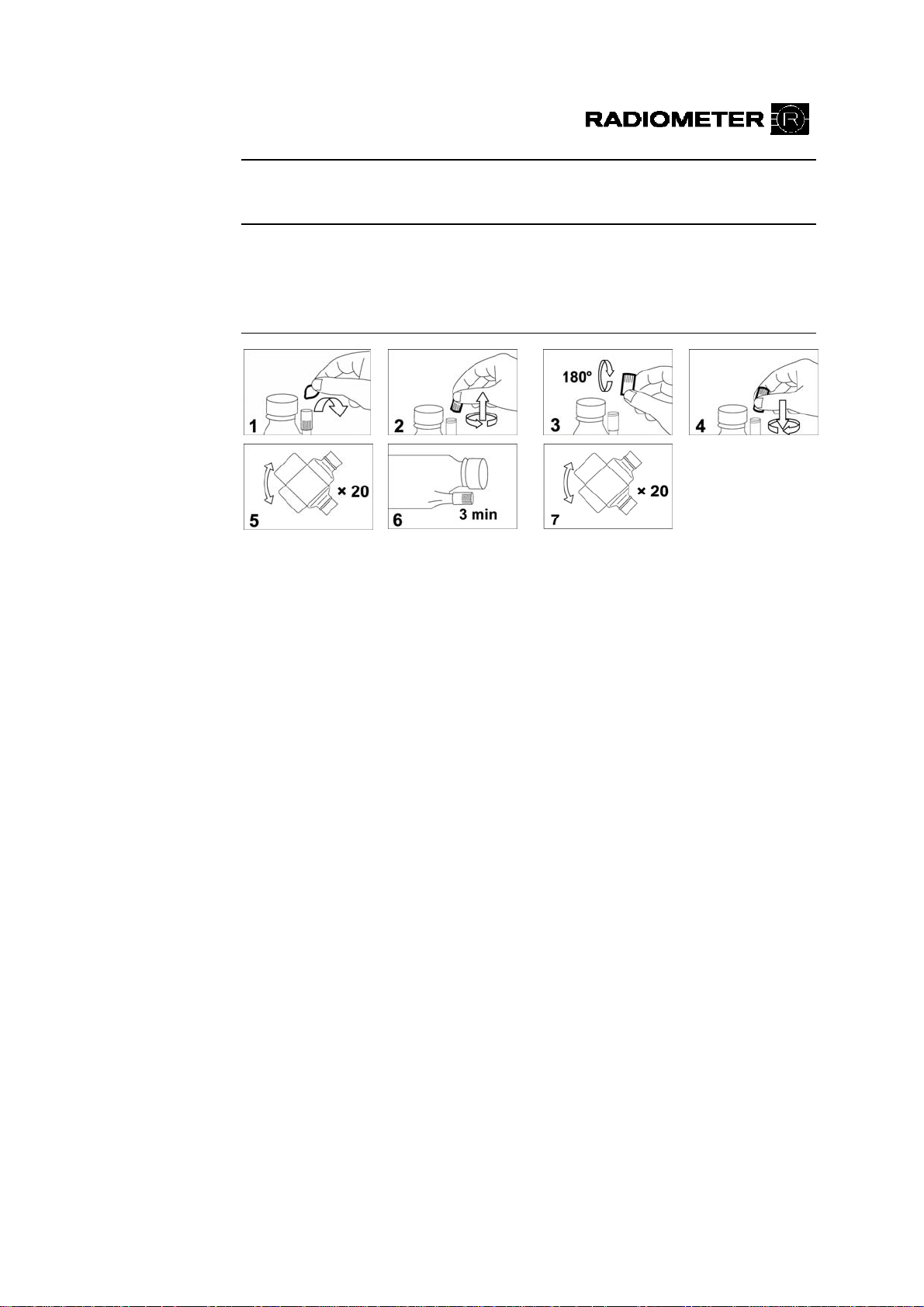
The procedure for adding cleaning additive has been changed for the abovementioned analyzers and from now on the following instructions must be followed:
1.
2.
Remove the foil from the DosiCapZip and unscrew it (Figs. 1+2).
Turn the DosiCapZip upside down and screw it onto the container again
(Figs. 3+4).
TCAUTIONT: TIf the contents of the DosiCapZip or the container have
been spilt by accident, both the container and the DosiCapZip should be
3.
4.
discarded to prevent incorrect concentrations in the solution.
Invert the container at least 20 times to dissolve the additive (Fig. 5).
Place the container horizontally so that the solution may enter the
T
DosiCapZip and leave it for 3 minutes (Fig. 6).
5.
Invert the container again at least 20 times to fully dissolve the additive
(Fig. 7).
6.
7.
Unscrew the lid from the new solution container.
Remove the used solution container by holding it on the sides and
pulling.
8.
9.
Scan the barcode of the new solution, using the barcode reader.
Place the new solution container in position on the analyzer and push it
firmly onto the connector as far as possible.
10.
For the ABL700 Series analyzers, sw. 3.836: Press Restart to restart the
analyzer.
For the ABL700 Series analyzers, sw. 6.00: Press Restart and Accept to
restart the analyzer.
© Radiometer Medical ApS, 2700 Brønshøj, Denmark, 2008. All Rights Reserved.
994-702. 200810A.
Page 8

Cleaning
solution with
cleaning
additive –
general
information
Cleaning Solution 175 mL 944-123 S7375
T
Use: For cleaning the measuring system of the ABL700 Series analyzers.
Contains: Salts, buffer, anticoagulant, preservatives, surfactants and enzyme.
Safety Data Sheet may be obtained from your local distributor.
Item Code No. Type
Storage: At 2-10 °C.
Stability in use: The Cleaning Solution with the Cleaning Additive is stable for 2
months in use.
Analyzer: Perform cleaning every 8th hour.
T CAUTION – Risk of personal injury
TDo not breathe dust (S22). Avoid contact with skin (S24). Irritating to eyes and
skin (R36/38). Wear suitable gloves (S37). May cause sensitization by inhalation
and skin contact (R42/43). In case of accident or if you feel unwell, seek medical
advice immediately (show the label where possible) (S45).
Texts no longer
valid in the
manuals
Due to new cleaning solutions, information about Cleaning solution S7370 and
Cleaning additive S5370 is no longer valid.
Below is a list of the sections in the manual that must be ignored.
ABL700 Series reference manual:
Technical
documentation
Instructions to
user
Chapter 7: Solutions and gas mixtures:
S7370 Cleaning Solution and
S5370 Cleaning additive:
Text no longer relevant.
See instruction about the new Cleaning
Solution S7375 above instead.
Index: Cleaning Additive references no longer
relevant.
The manuals for the ABL700 Series analyzers will be updated with the above
information when reprinted.
This update kit includes a note to the user with the changes and a new date of issue
page of the manual. Please place the note to the user in the binder of the ABL700
Series reference manual and replace the date of issue page with the new
corresponding page, then discard the old page.
Page 9

Reference
ABL700 Series
1. Introduction
2. Electrodes
3. The Optical System
Contents
Manual
4. User-defined Corrections
5. Performance Characteristics
6. Parameters
7. Solutions
8. Interfacing Facilities
Index
Date of Issue
Page 10

SYSTEM PERFORMANCE AND WARRANTY DISCLAIM
Radiometer cannot provide or verify instrument performance characteristics and accept
warranty claims or product liability claims if the recommended procedures are not carried out,
if accessories other than those recommended by Radiometer are used, or if instrument
repairs are not carried out by authorized service representatives.
The instructions given in the Operator’s Manual for the ABL700 Series must be observed in
order to ensure proper instrument performance, and to avoid electrical hazards.
TRADEMARKS
ABL™, BMS™, FLM™, CMT™, Deep Picture™, QUALICHECK™ and RADIOMETER™ are
trademarks of Radiometer Medical ApS, Denmark.
ABL is registered in the USA.
QUALICHECK is registered in the USA and in some other countries.
COPYRIGHT
The contents of this document may not be reproduced in any form or communicated to any
third party without the prior written consent of Radiometer Medical ApS.
While every effort is made to ensure the correctness of the information provided in this
document Radiometer Medical ApS assumes no responsibility for errors or omissions which
nevertheless may occur.
This document is subjected to change without notice.
©Radiometer Medical ApS, DK-2700 Brønshøj, Denmark, 2006. All Rights Reserved.
Page 11

ABL700 Series Reference Manual Contents
Contents
1. Introduction .............................................................................................. 1-1
ABL700 Series Documentation .................................................................. 1-2
Warnings/Cautions and Notes .................................................................... 1-3
2. Electrodes.................................................................................................. 2-1
General Construction .................................................................................. 2-2
General Measuring Principles..................................................................... 2-3
Calibration .................................................................................................. 2-7
Electrode Measuring Time and Updatings ............................................... 2-14
Reference Electrode.................................................................................. 2-15
pH Electrode ............................................................................................. 2-16
pCO
Electrode ......................................................................................... 2-23
2
Electrode............................................................................................ 2-32
pO
2
Electrolyte Electrodes ............................................................................... 2-42
Metabolite Electrodes ............................................................................... 2-54
References................................................................................................. 2-64
3. The Optical System ................................................................................... 3-1
Measuring Principle.................................................................................... 3-2
Correcting for Interferences........................................................................ 3-7
Calibration .................................................................................................. 3-9
Measurement and Corrections .................................................................. 3-10
References................................................................................................. 3-13
4. User-Defined Corrections ......................................................................... 4-1
General Information.................................................................................... 4-2
Correction Factors for Oximetry Parameters and Bilirubin........................ 4-4
Electrolyte and Metabolite Parameters ....................................................... 4-8
5. Performance Characteristics.................................................................... 5-1
General Information.................................................................................... 5-2
Definition of Terms and Test Conditions ................................................... 5-3
Reference Methods for the ABL700 Series ................................................ 5-8
ABL735/30/25/20/15/10/05 Performance Test Results - Macromodes.... 5-10
ABL735/30/25/20/15/10/05 Performance Test Results - Micromodes .... 5-19
ABL700 Performance Test Results .......................................................... 5-30
ABL735/30/25/20/15/10/05/00 Expired Air Mode .................................. 5-32
ABL735/30/25/20/15/10/05/00 Capillary - pH Only Mode ..................... 5-35
i
Page 12

Contents ABL700 Series Reference Manual
ABL735/30 Performance Test Results - Bilirubin.................................... 5-36
Interference Tests...................................................................................... 5-42
References................................................................................................. 5-50
6. Parameters ................................................................................................. 6-1
General Information.................................................................................... 6-2
Acid-base Parameters.................................................................................. 6-6
Oximetry Parameters .................................................................................. 6-8
Oxygen Parameters ..................................................................................... 6-9
Bilirubin.................................................................................................... 6-13
Electrolyte Parameters .............................................................................. 6-14
Metabolite Parameters .............................................................................. 6-15
Units and Ranges for Measured Parameters ............................................. 6-16
Units and Ranges for Input Parameters .................................................... 6-19
Units and Ranges for Derived Parameters ................................................ 6-20
List of Equations....................................................................................... 6-25
Oxyhemoglobin Dissociation Curve (ODC)............................................. 6-41
Conversion of Units.................................................................................. 6-46
Default Values .......................................................................................... 6-48
Altitude Correction ................................................................................... 6-49
References................................................................................................. 6-50
7. Solutions and Gas Mixtures ..................................................................... 7-1
General Information.................................................................................... 7-2
S1720 and S1730 Calibration Solutions ..................................................... 7-3
S4970 Rinse Solution ................................................................................. 7-4
S7370 Cleaning Solution and S5370 Cleaning Additive............................ 7-5
S7770 tHb Calibration Solution.................................................................. 7-6
Gas Mixtures (Gas 1 and Gas 2) ................................................................. 7-7
Electrolyte Solutions................................................................................... 7-8
S5362 Hypochlorite Solution ..................................................................... 7-9
Certificates of Traceability ....................................................................... 7-10
8. Interfacing Facilities ................................................................................. 8-1
Connecting a Mouse ................................................................................... 8-2
Connecting an Alphanumeric Keyboard..................................................... 8-3
Connecting the Bar Code Reader................................................................ 8-4
Connecting a Network ................................................................................ 8-6
Index
Date of Issue
ii
Page 13

ABL700 Series Reference Manual 1. Introduction
1. Introduction
Overview
This section gives an introduction to the documentation that accompanies your
ABL700 Series analyzer. It describes how this particular manual is organized and
explains the different notices that appear in it.
Contents
This chapter contains the following topics.
ABL700 Series Documentation ....................................................................... 1-2
Warnings/Cautions and Notes.......................................................................... 1-3
1-1
Page 14

1. Introduction ABL700 Series Reference Manual
ABL700 Series Documentation
ABL700 Series
Analyzers
Documentation
The documentation that accompanies the ABL700 Series analyzers covers the
series in general - each possible electrode combination is not considered
individually.
The table below describes the documentation that comes with each analyzer.
Documentation Description
Design of
Manual
The Operator’s
Manual
Contains all the information required for everyday
operation of the analyzer.
Describes the functions of the analyzer and how to set it up
according to customer needs and requirements.
Explains error messages and gives troubleshooting
procedures.
Contains ordering information
The Reference
Manual
Gives detailed information about the operating principles
of the analyzer.
Describes the measuring and calibrating principles.
Lists all the parameters.
Gives the equations from which the derived parameters are
calculated.
Gives information about how the performance of the
analyzer is tested.
On-line Help Summarizes the information found in the Operator’s
Manual.
Gives hands-on help at the analyzer.
Depending on the set up of your analyzer, the entire Reference Manual may not be
applicable to it. However the manual is designed in such a way that it is easy to
disregard or remove the sections that are not relevant to your instrument.
1-2
Page 15

ABL700 Series Reference Manual 1. Introduction
Warnings/Cautions and Notes
Definitions
List of
WARNING/
CAUTION
Notices
The following table indicates the type of information given in warnings, cautions,
and notes:
Notice Definition
WARNING
Warnings alert users to potentially serious outcomes to
selves or to the patient (such as death, injury, or serious
them
adverse events).
PRECAUTION
Precautions alert users to exercise the special care necessary
for safe and effective use of the device. They
may include
actions to be taken to avoid effects situations on patients or
users that may not be potentially life threatening or result in
serious injury , but about which the user should be aware.
Precautions may also alert the user to adverse effects on the
device caused by use or misuse, and the care required to
avoid such effects.
NOTE
Notes give practical information.
All WARNING/CAUTION notices that appear in this manual, are listed below.
S5370 Cleaning Additive: May cause sensitization by inhalation and skin
•
contact). Do
not breathe dust. Avoid contact with skin. Wear suitable gloves.
In case of accident or if you feel unwell, seek medical advice immediately
(show the label where possible).
Gas Mixtures: Not for drug use. High pressure gas. Do not puncture. Do not
•
store near heat or open flame - exposure to temperatures above 52 C
o
(125 F) may cause contents to vent or cause bursting.
Not for inhalation. Avoid
breathing gas - mixtures containing carbon dioxide
o
can increase respiration and heart rate. Gas mixtures containing less than
19.5 % oxygen can cause rapid suffocation.
Store with adequate ventilation. Avoid contact with oil and grease.
Only use with equipment rated for cylinder pressure.
Use in accordance with Safety Data Sheet.
1-3
Page 16

Page 17

Introduction
Contents
2. Electrodes
This chapter describes the construction, measuring principle and calibration
process for each of the electrodes in the ABL700 Series analyzers.
General sections covering the background theory used for measurements and
calibrations are also presented here.
This chapter contains the following topics.
General Construction ....................................................................................... 2-2
General Measuring Principles .......................................................................... 2-3
Calibration........................................................................................................ 2-7
Electrode Measuring Time and Updatings....................................................... 2-14
Reference Electrode ......................................................................................... 2-15
pH Electrode .................................................................................................... 2-16
Electrode................................................................................................. 2-24
pCO
2
Electrode ................................................................................................... 2-33
pO
2
Electrolyte Electrodes ...................................................................................... 2-43
Metabolite Electrodes....................................................................................... 2-55
References........................................................................................................ 2-65
Page 18
2. Electrodes ABL700 Series Reference Manual
General Construction
An Electrode
In this manual and other Radiometer literature, the term electrode refers to the
whole sensor unit, i.e. both the electrode and the electrode jacket. Radiometer
electrodes are cordless, thereby limiting the level of noise picked up during the
measuring process. The electrical signals from the electrodes are amplified by
preamplifiers placed in each module.
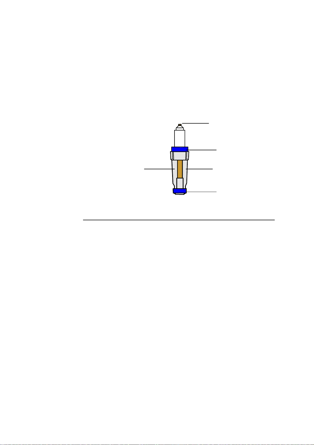
A generalized diagram of a Radiometer electrode is given below.
Electrolyte solution
Electrical contact
Color-coded ring
Electrode jacket
Membrane
The main electrode parts are described below.
Part Description
Electrical contact Provides electrical contact between the electrode and the
analyzer.
Color-coded ring Marks each electrode for easy recognition.
Electrode jacket Holds the electrolyte solution and membrane, and protects
the electrode.
Membrane A thin sheet-like material to separate the sample from the
electrode, that differentiates between the substances
allowed to pass through it towards the electrode.
2-2
Electrolyte
solution
A conducting solution to provide an electric contact
between the electrode and the sample (also known as a
salt-bridge solution).
More specific descriptions of the electrodes are found under the appropriate
electrode titles in this chapter.
Page 19
ABL700 Series Reference Manual 2. Electrodes
General Measuring Principles
Introduction
There are two different measuring principles employed for electrodes in the
ABL700 Series.
• Potentiometry: The potential of an electrode chain is recorded using a
voltmeter, and related to the concentration of the sample (the Nernst equation).
• Amperometry: The magnitude of an electrical current flowing through an
electrode chain, which is in turn proportional to the concentration of the
substance being oxidized or reduced at an electrode in the chain.
These two measuring principles are described in detail on the following pages.
Potentiometric
Method
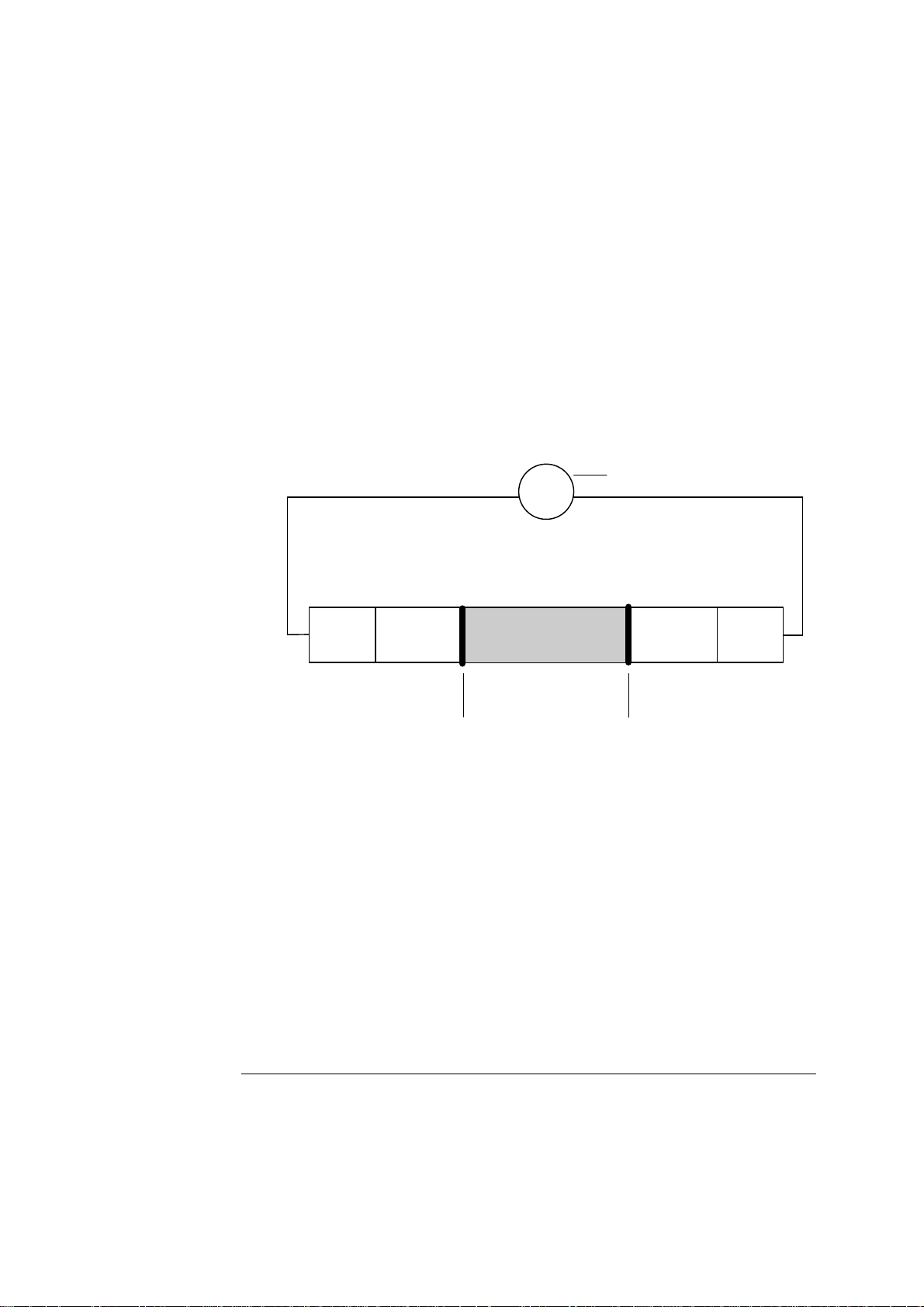
An electrode chain describes an electrical circuit consisting of a sample, electrode,
reference electrode, voltmeter, membranes, and electrolyte solutions.
Voltmeter
V
Reference
electrode
Electrolyte
solution
Membrane
Sample
Electrolyte
solution
Membrane
Electrode
Every element in the electrode chain contributes a voltage to the total potential
drop through the chain. Thus:
• When immersed in the appropriate electrolyte solution, both electrodes have
separate potentials.
• The membrane junctions between the sample and electrolyte solutions also have
separate potentials.
The complete electrode chain potential therefore, is the sum of these separate
potentials and is the quantity measured by the voltmeter.
E = E – E
total sample Ref
where the final unknown potential (E
electrode chain potential (E
) and the reference potential (E
total
) can be calculated knowing the total
sample
that is constant
Ref
between two subsequent calibrations).
Continued on next page
2-3
Page 20

2. Electrodes ABL700 Series Reference Manual
General Measuring Principles, Continued
Potentiometric
Method
(continued)
Having measured the unknown potential (E
applied to determine the activity (a
EE
) of the species under study:
x
=+
sample
0
where:
E0
R =
T
n
F =
a
= standard electrode potential
gas constant (8.3143 JK
= absolute temperature (310 K (37
= charge on the ion
Faraday constant (96487 C mol
x
= activity of
x
−1
mol−1)
The Nernst equation is rearranged to express the activity as a function of the
potential
E
. Having measured E
sample
the activity can be calculated since all
sample
other quantities are already known. Finally the analyzer converts activity to
concentration.
), the Nernst equation is then
sample
23R
.
T
log
a
n
−1
F
o
C ))
)
x
Strictly speaking, in potentiometry the potential of an electrode chain or the
magnitude of current flowing through an electrical chain is related to the activity of
a substance, and not its concentration.
Activity expresses the ‘effective concentration’ of a species, taking non-ideality of
the medium into account.
Activity and concentration are related by the following equation:
a
= γ c
x
x
where:
a
= the activity of the species x
x
= the activity coefficient of species x under the measurement conditions
γ
(for ideal systems
c
= the concentration of species x (mmol/L)
x
γ = 1)
NOTE:
To be exact, activity is related to the molality of species x, i.e., the number
of mmoles per kg of solvent. However molality is converted to concentration
(molarity).
ABL700 Series analyzers automatically convert activities into concentrations
[1].
The term concentration is therefore used in explanations of the measuring
principles for each of the electrodes further on in this chapter.
2-4
The potentiometric measuring principle is applied in the pH,
pCO
electrodes. It is slightly different for the
electrode, however, since the Nernst
2
equation is not directly applied.
pCO
, and electrolyte
2
Continued on next page
Page 21
ABL700 Series Reference Manual 2. Electrodes
A
General Measuring Principles, Continued
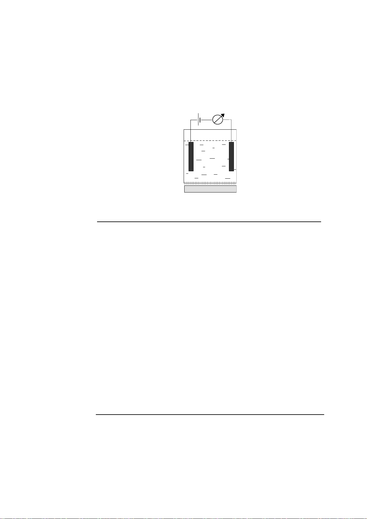
Amperometric
Method
The electrode chain in amperometric measurements consists of the sample, the two
electrodes (anode and cathode), an amperemeter, a voltage source, the membranes,
and the electrolyte solutions.
Applied voltage
Anode Cathode
Electrolyte solution
Sample
mperemeter
Membrane
Part Function
Cathode Negative electrode where a reduction reaction occurs and
electrons are consumed.
Anode Positive electrode where an oxidation reaction occurs and
electrons are released.
Electrolyte
Provides electrical contact between the anode and cathode.
solution
Membrane Allows the appropriate molecules to pass through from the
sample.
Sample Contacts the membrane.
Applied voltage Applies the necessary potential for the reduction or oxidation
reaction under study.
Amperemeter Measures the current flowing through the circuit.
To simplify the description of the measuring process in an amperometric electrode,
we make the following assumptions:
• there is a species A in the sample which is reduced at the cathode to A
• there is a species X in the electrolyte which is oxidized at the anode to X
−
.
+
.
Continued on next page
2-5
Page 22

2. Electrodes ABL700 Series Reference Manual
General Measuring Principles, Continued
Amperometric
Method
(continued)
The membrane is selective to the species A, allowing no other species but it to pass
through from the sample into the electrolyte solution.
As an appropriate potential is applied across the electrodes, the species
A is
reduced at the cathode according to the following reaction:
A + e
−
→ A
−
The reduction of A produces a flow of electrons, i.e. an electrical current.
To complete the electrical circuit an oxidation reaction where electrons are
released is necessary. Therefore species
X is oxidized according to the following
reaction:
+
X
→ X
+ e
−
The magnitude of the current flowing through the circuit is proportional to the
concentration of the species being reduced, in this case species
thereby automatically calculates the concentration of
A in the sample.
A. The analyzer
The amperometric measuring principle is applied in the
electrodes.
pO
, glucose, and lactate
2
2-6
Page 23
ABL700 Series Reference Manual 2. Electrodes
−
−
−
Calibration
Actual Electrode
Condition
Calibration Line
The electrodes are active elements and must be calibrated regularly as the signals
from the electrodes change with, e.g. age or deposits on the membrane.
Calibration relates the electrode signals during the calibration sequence to the
values of the calibrating solutions and must be performed at regular intervals so
that the accuracy can be constantly refined after inevitable minor changes in the
electrodes’ behavior.
Actual electrode condition is described by status/zero point and sensitivity and
compared with theoretical conditions for an "ideal" electrode. In addition to status
and sensitivity, an electrode condition is described by drift.
The calibration line expresses the relationship between the potential (or current)
measured at an electrode, and the concentration of the species specific to the
electrode. The calibration line forms the basis of the scale used by the analyzer to
convert electrode chain potentials to concentrations. Each electrode has a different
calibration line.
The pH electrode is used as an example to illustrate how this line is derived from
two calibration solutions of known pH.
• Cal 1 solution has a pH of 7.398 that gives potential reading of −100 mV.
• Cal 2 solution has a pH of 6.802 that gives a potential reading of −64 mV.
These two values are plotted on a graph.
The relationship between potential and pH is linear so a line can be drawn between
the two points, as shown below:
Measured
potential
(mV)
64
Calibration line
7.398
pH of Cal 1 sol.
pH
100
97
6.802
pH of Cal 2 sol.
7.346
pH of sample
The calibration line now forms the scale used to convert the potential measured at
the pH electrode during sample analysis to an actual pH value.
Continued on next page
2-7
Page 24
2. Electrodes ABL700 Series Reference Manual
Calibration, Continued
Calibration Line
(continued)
A blood sample gives a potential reading of -97 mV at the pH electrode. Reading
off from the calibration line shown below, this potential corresponds to a pH of
7.346.
Measured
potential
(mV)
64
−
Theoretical
Calibration Line
Calibration line
7.398
pH of Cal 1 sol.
pH
−
97
−
100
6.802
pH of Cal 2 sol.
7.346
pH of sample
The calibration line is updated at every calibration. Drift describes the variation in
the calibration line between consecutive calibrations.
The theoretical calibration line is the relationship between potential and
concentration in a potentiometric measurement, or the relationship between current
and concentration in an amperemetric measurement.
In the ABL700 Series the theoretical calibration line for pH is defined by the
following two points:
pH Electrode potential
(vs. Ref. potential)
6.800
7.400
Measured
potential (mV)
−75.5 mV
−112.4 mV
2-8
−75.5
−112.4
6.8
7.4
pH
The position and slope of the calibration line compared to the theoretical
calibration line are described by the status and sensitivity respectively.
Continued on next page
Page 25
ABL700 Series Reference Manual 2. Electrodes
Calibration, Continued
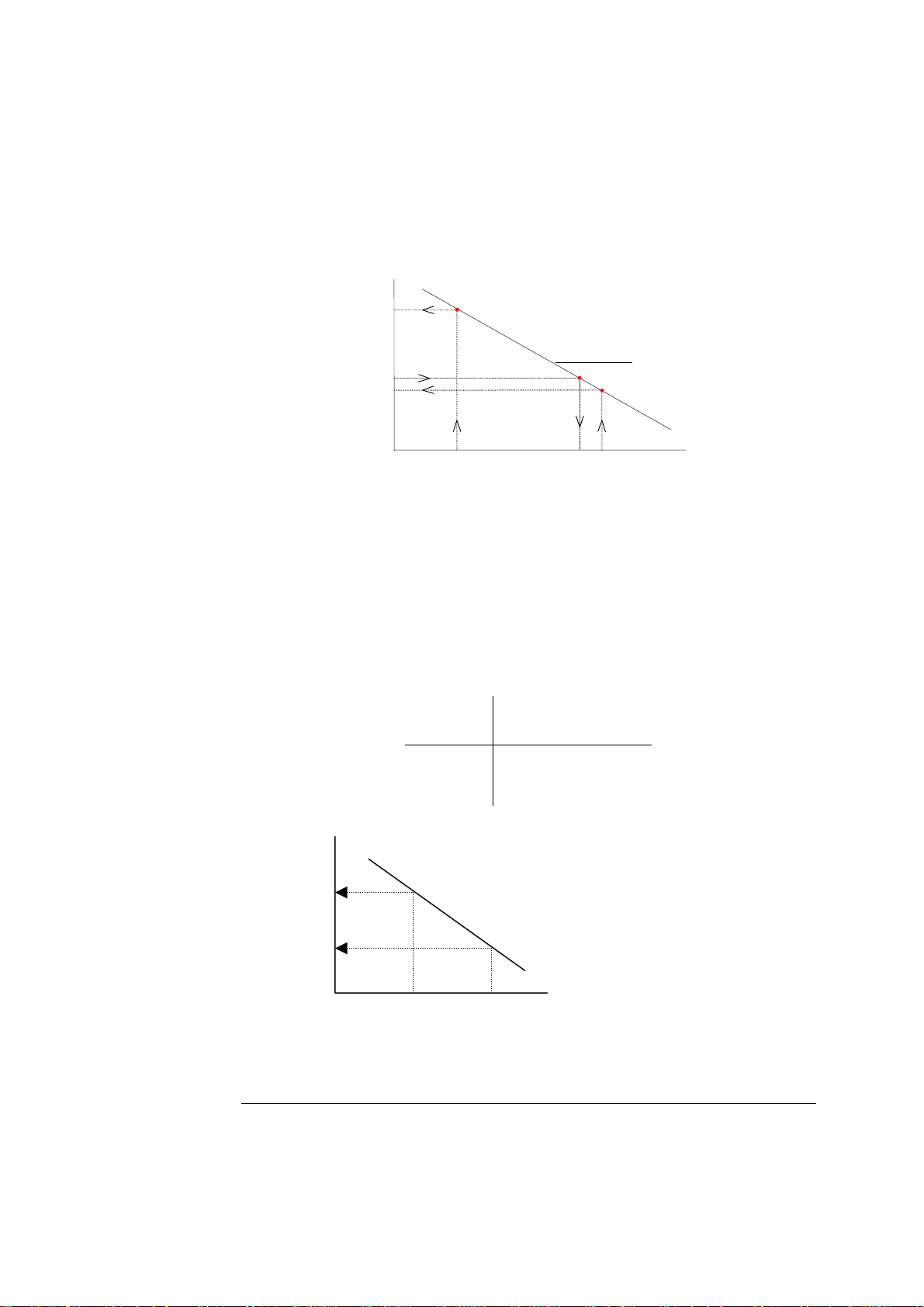
Sensitivity
Electrode sensitivity expresses how a real electrode measures compared with the
specified values of the calibration material; it illustrates the slope of the calibration line
derived from a 2-point calibration as a percentage (or fraction) of the slope of the
theoretical calibration line, as determined by the Nernst equation of the ion in question.
Calculating the sensitivity is a way of monitoring the deviation of the electrode
sensitivity from the theoretical value.
Calculation of the sensitivity is shown, using the pH electrode as an example.
A theoretical calibration line for the pH electrode with a slope of
−61.5 mV/pH is
drawn:
Measured
potential
(mV)
75.5
−
Theoretical calibration line
112.4
−
6.8
7.4
pH
The calibration line from a 2-point calibration is superimposed on the same graph:
Measured
potential
(mV)
−
75.5
2-point calibration line
Slope = −58.4 mV/pH
Sensitivity = 95 %
Theoretical calibration line
112.4
−
6.8
Slope= −61.5 mV/pH
Sensitivity = 100 %
7.4
pH
The sensitivity of the electrode is calculated as the ratio between the slope of the 2point calibration line and that of the theoretical line, expressed as a percentage or
fraction.
If the theoretical calibration line is assumed to have a sensitivity of 100 %, the 2point calibration line shown in the example will have a sensitivity of
approximately 95 %.
Continued on next page
2-9
Page 26
2. Electrodes ABL700 Series Reference Manual
Calibration, Continued
Sensitivity
(continued)
Status
The sensitivity limits for the calibration are set for each electrode. If the sensitivity
of any electrode falls outside the allowed limits, the message
out of range
appears in the Calibration Messages, with the particular electrode
Calibration Sensitivity
specified.
The electrode status is a measure of zero point of a complete electrode chain.
Status of a real electrode reflects deviations from the conditions of a theoretical
electrode, and define the position of the calibration line.
Calculating the status value of an electrode is a way of monitoring the position of
the calibration line despite the fact that only a 1-point calibration has been carried
out. The calculation of the status is shown, using the pH electrode as an example.
A calibration line with the same slope as the theoretical calibration line (
−61.5
mV/pH) is drawn through this point. This theoretical calibration line is used since
no 2-point calibration is performed which would otherwise give an actual
calibration line.
Measured
potential
(mV)
Theoretical calibration
line with a slope = −61.5
mV/pH drawn through
E
Cal 1
pH
A pH of 7.400, the nominal pH of Calibration Solution 1 (pH
corresponding potential (
E
) is read off the theoretical calibration line that
Cal 1 nom
the point from a 1-point
calibration.
pH
Cal 1
) is chosen. Its
Cal 1 nom
was drawn through the 1-point calibration point.
Measured
potential
(mV)
Theoretical calibration line for the
theoretical pH electrode with known
potential of −112.4 mV at a pH =
7.400.
2-10
E
Cal 1 nom(theo)
E=−112.4 mV
E
Cal 1 nom
E
Cal 1
∆pH
E
∆
Theoretical calibration
line drawn through the 1point calibrat ion point.
pH
Status
pH
Cal 1 nom
(7.400)
pH
Cal 1
pH
Continued on next page
Page 27

ABL700 Series Reference Manual 2. Electrodes
−
Calibration, Continued
Status
(continued)
A line from pH
corresponding potential (
is extrapolated up to the theoretical calibration line, and the
Cal 1 nom
E
Cal 1 nom(theo)
) read off the theoretical calibration line.
Calibration
Materials
The difference between
E
Cal 1 nom
and E
Cal 1 nom(theo)
which corresponds to ∆E on the
graph, represents the potential that should theoretically be obtained for a solution
with pH = 7.400. This potential difference (
∆E) thus describes the deviation of the
actual pH reference electrode system from a theoretical electrode system.
Similarly
∆pH describes the deviation in pH values that would be produced
between measurements with an actual electrode system and measurements with a
theoretical electrode system.
The status of the pH electrode, pH(Status), is then calculated as:
pH(Status) = 7.4 +
Cal 1 nom Cal 1 nom(theo)
EE
61.5
The status limits of the calibration are set for each electrode. If the status for any
electrode falls outside the allowed limits, the message
appears in the Calibration Messages, with the particular electrode specified.
limits
Calibration status out of
The following calibration materials are used:
Calibration Material Used for...
Calibration Solutions 1 and 2: the exact composition of
the calibration solutions is given in the bar code on the
bottle label, which can be read into the analyzer using the
Calibration of the pH,
and electrolyte
electrodes
bar code reader, or entered manually via the keyboard.
Calibration Solution 1: Calibration of the
metabolite electrodes
and optical system
Gas 1 and Gas 2: each gas has a precise composition
essential for determining the accuracy of the analyzer in
each pCO
and pO
2
measurement.
2
Calibration of the
pCO
and pO
2
2
electrodes
tHb Calibration Solution: Calibration of the
optical system
The Chemical Reference Laboratory at Radiometer is responsible for the accuracy
of the calibrating solutions and gases.
Traceability certificates for individual solutions are presented in Chapter 7 of this
manual.
Continued on next page
2-11
Page 28
2. Electrodes ABL700 Series Reference Manual
t
d
t
d
t
t
d
t
d
Calibration, Continued
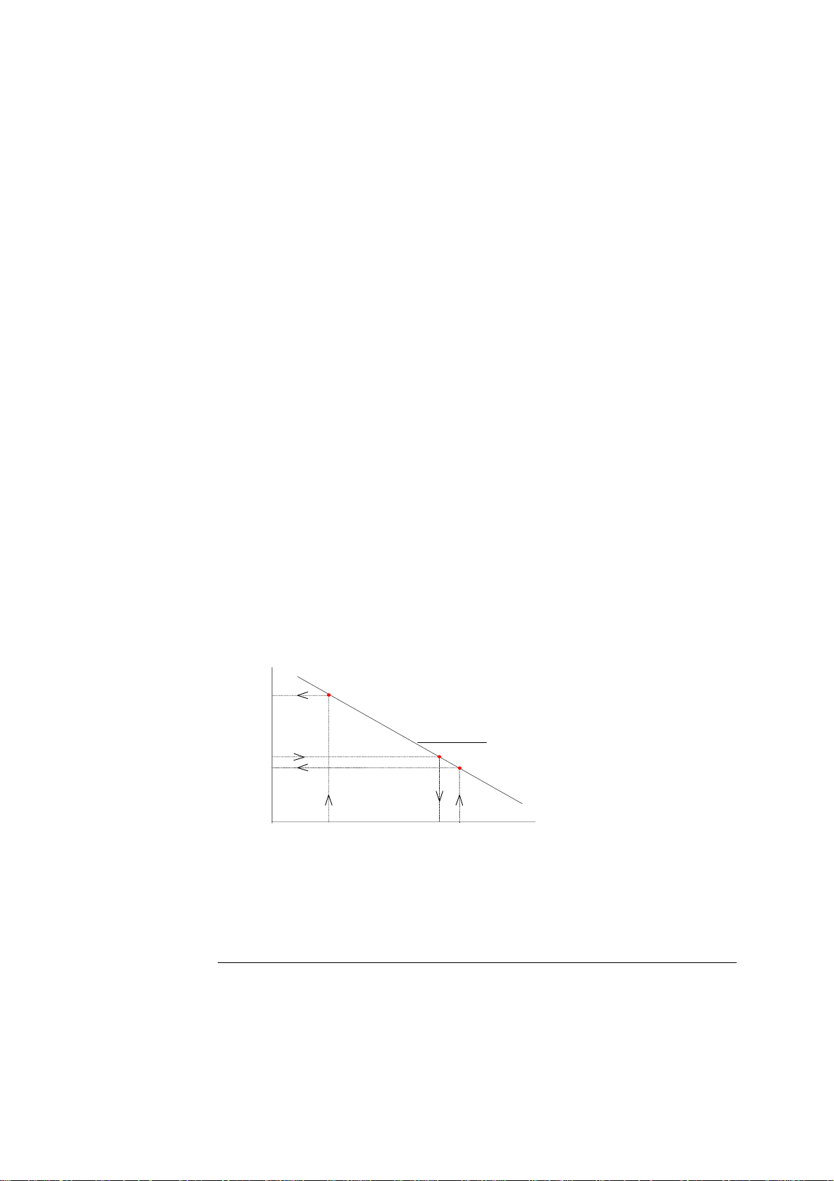
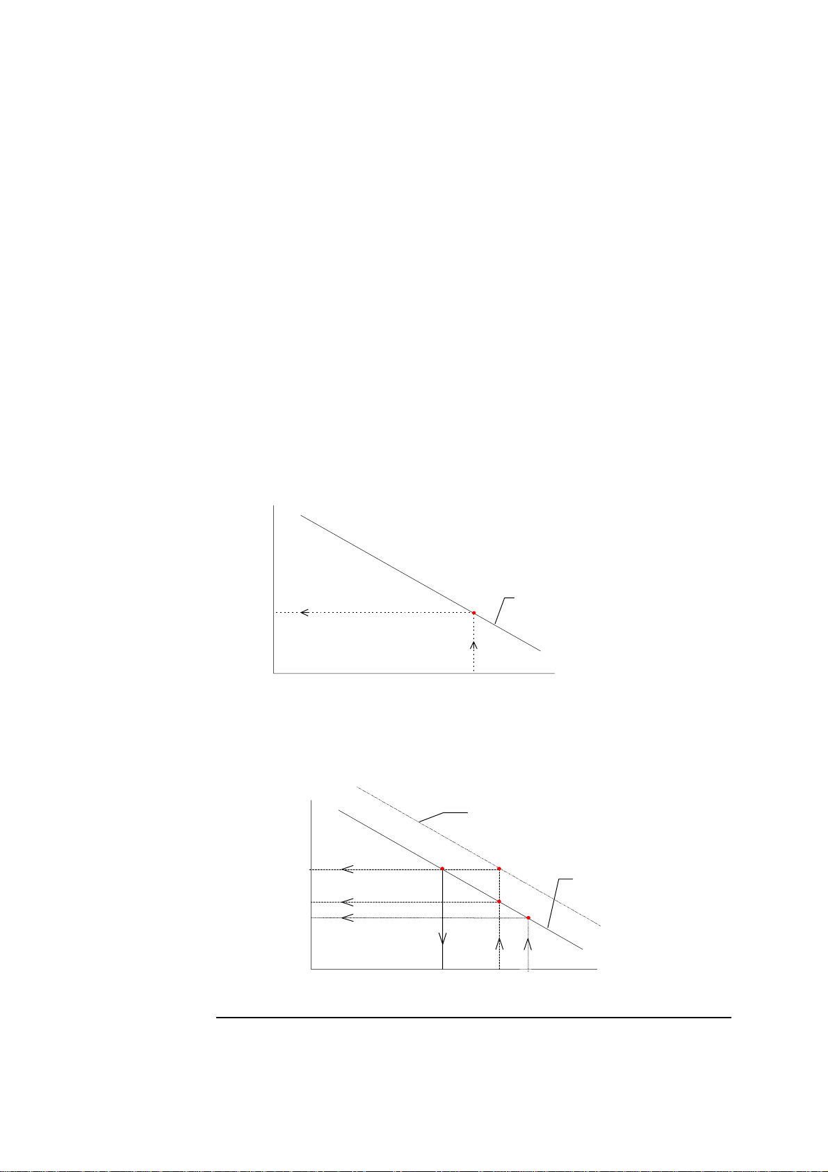
Drift
Drift is defined as the difference measured by the electrodes during last and
previous calibrations, and is a measure of the electrode stability.
Drift 1 is obtained on Calibration Solution 1 and/or Gas 1 and is calculated as
follows, using the pH electrode as an example:
Measured
potential
Calibration line from last
2-point calibration
(mV)
n
2
1-point calibration
n
2
Drift 1 value
s
1
Drift 1 value
s
1
1-point calibration
2-point calibration
pH
Calibration Solution 2
pH
Calibration Solution 1
pH
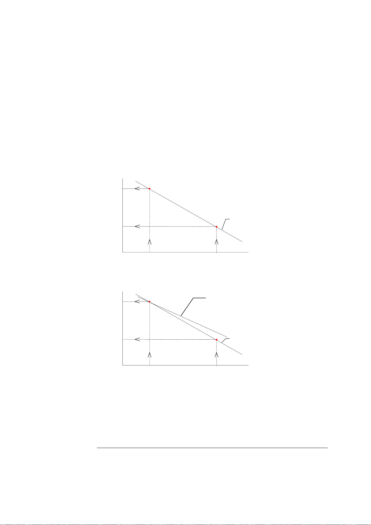
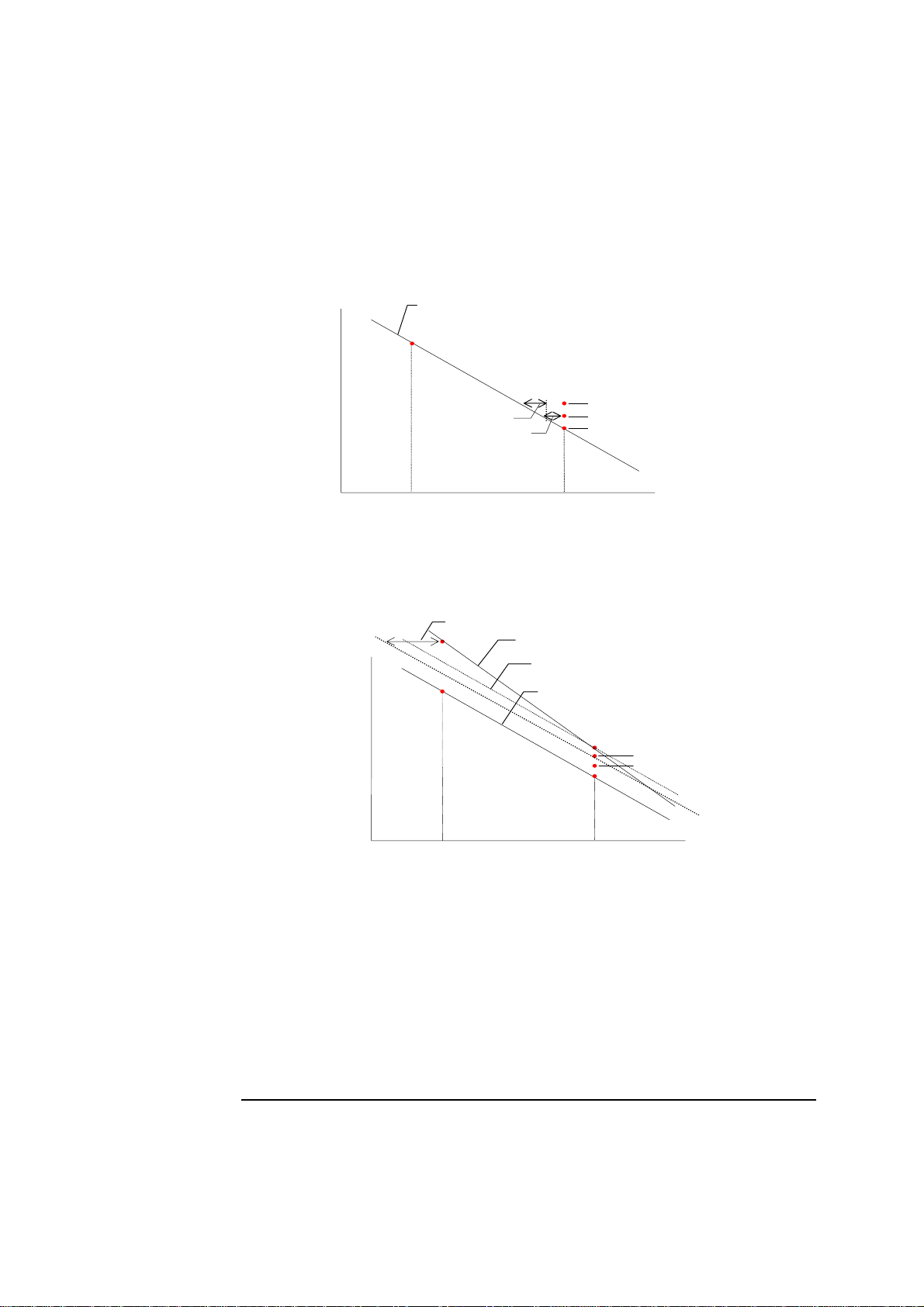
Drift 2 is obtained after 2-point calibration. The pH electrode is used as an
example and the calibration schedule is set so that each 2-point calibration is
separated by two 1-point calibrations.
Measured
potential
(mV)
Drift 2
Calibration line from 2
Slope of 1
Calibration line from 1
n
2-point calibration
s
2-point calibration line
s
2-point calibration
n
2
1-point calibration
s
1
1-point calibration
pH
Calibration Solution 2
pH
Calibration Solution 1
pH
Drift tolerances express the extent to which drift values for an electrode can
fluctuate before the electrode is deemed unstable and thus incapable of providing
reliable calibrations.
The drift tolerances for each electrode are set in the analyzer’s Setup programs.
Radiometer recommends the use of the default drift tolerances, as too narrow drift
tolerances will cause electrode drift errors even for normal electrode fluctuations.
If the drift tolerances are too wide, significant measurement errors will result
without warning.
Continued on next page
2-12
Page 29

ABL700 Series Reference Manual 2. Electrodes
Calibration, Continued
Drift (continued)
If the drift values for any electrode fall outside the drift tolerances, the message
Calibration drift out of range appears in the Calibration Messages, with the
particular electrode specified.
No drift values are reported for startup calibrations as there are no previous
calibrations available for comparison.
2-13
Page 30

2. Electrodes ABL700 Series Reference Manual
Electrode Measuring Time and Updatings
Measuring Time
Updatings
In the ABL700 Series analyzers the measuring time of the electrode is independent
of the electrode type. Electrode signals are registered at 0.982 second intervals
during both calibrations and measurements. The registration of each electrode
signal begins after the samples, calibration solutions, and calibration gases are in
position in the measuring modules.
The duration of each calibration is predetermined, as is the number of updatings of
the electrodes’ signals.
In general, the updatings from an electrode response are numbered from 1 to upd
last, where updating number 1 is the first updating and upd last is the last. The
diagram below schematically illustrates the electrode response that is calculated on
uncorrected electrode updating values in the ABL700 Series.
Signal
Upd 1 Upd last
Updatings
2-14
Page 31

ABL700 Series Reference Manual 2. Electrodes
A
Reference Electrode
Electrode
Description
The reference electrode is used in the measurement of pH and electrolyte
parameters and is located in the pH/Blood Gas module.
The reference electrode maintains a stable, fixed potential against which other
potential differences can be measured. The potential is not altered by sample
composition.
A fixed potential is maintained at the reference electrode by the following
equilibrium reactions:
AgCl ⇔ Ag + Cl
+ −
Ag + e ⇔ Ag
+ −
These reactions are possible because the electrode is made from a Ag rod coated
with Ag to provide the Ag/Ag
+
equilibrium and determine the reference potential.
Electrode contact
The electrolyte solution acts as a salt-bridge
solution that maintains an electrical contact
between the coated Ag wire and the sample.
Rubber ring
The solution is 4 M sodium formate
(HCOONa), adjusted to pH 5.5 with
hydrochloric acid.
The chloride concentration in the electrolyte
Electrolyte
solution is adjusted in accordance with the
chloride concentration in the rinse solution,
g rod coated with Ag
to reduce Cl
−
exchange across the
membrane, thereby obtaining a more stable
potential.
3-layer membrane
The electrode is encased in the electrode
jacket: The rubber ring seals the electrode in
the jacket to prevent evaporation or leakage
of the electrolyte solution.
The membrane consists of three separate membranes:
Membrane Function
Inner To limit diffusion through the membrane and stabilizes the whole
membrane system.
Middle To prevent protein interference.
Outer To reduce the interchange of sample or rinse solution and
HCOONa solution.
Packaging
The E1001 reference electrode comes in a box with an insert explaining the
preparation of the electrode and its use.
2-15
Page 32

2. Electrodes ABL700 Series Reference Manual
A
pH Electrode
Description
Electrode Chain
Potentials
The pH electrode (E777) is a pH-sensitive glass electrode. The pH-sensitive glass
membrane is located at the tip and seals the inner buffer solution with a constant
and known pH.
The air bubble allows for expansion
of the inner buffer solution when the
electrode is thermostatted to 37
o
C.
The potential difference across the
glass membrane is due to a change
in the charge balance at the
membrane.
The glass membrane is sensitive to
+
H
ir bubble
Glass
membrane
ions. The metal ions in the glass
are exchanged with protons on either
side of the membrane, from the inner
buffer solution on one side and the
sample on the other.
A difference in the ion exchange on either side of the membrane occurs if the H
+
concentration (and therefore pH) is unequal on both sides. The number of positive
and negative ions is no longer equal, so the potential difference across the
membrane changes. If the H
+
concentrations on either side of the membrane are
equal, the potential difference will theoretically be 0 mV.
The total potential across the electrode chain is the sum of the potential differences
at each element in the chain:
Element Potential Symbol
Ag/AgCl electrode /electrolyte
solution. (Reference electrode)
Known and constant when the
Ag/AgCl wire is immersed in
the electrolyte solution.
Membrane junction between the
electrolyte solution in the
reference electrode and the
Known and constant.
Independent of sample
composition.
sample.
pH-sensitive glass membrane
between the sample and the pH
Unknown. Dependent on
sample composition.
electrode.
Ag/AgCl electrode/inner buffer
solution (pH electrode)
Known and constant when the
Ag/AgCl wire is immersed in
the inner buffer solution.
Total potential Measured by the voltmeter. E
Continued on next page
E
ref
E
MJ
E
Sample
E
E
tot
2-16
Page 33

ABL700 Series Reference Manual 2. Electrodes
(
++−
=−×
−
−
pH Electrode, Continued
Electrode Chain
Potentials
(continued)
Nernst Equation
The unknown potential difference across the pH-sensitive glass membrane is the
difference between the measured total potential and the sum of the known
potentials:
)
mVEEEE=E
The theoretical sensitivity of the pH electrode at 37
+
per pH unit, using pH = −log [H
], and converting concentration to activity, the
EMJreftotalsample
o
C being equal to −61.5 mV
Nernst equation can be expressed as:
Sensitivity
Status
EE615pH m
sample 0
.
V
The sensitivity of the pH electrode (SenspH) is obtained from the calibration line
obtained from a 2-point calibration on Calibration Solutions 1 and 2 (Cal 1 and Cal
2), and is calculated from the following equation:
Sens(pH)
= (fraction)
[]
Cal1)E(pH,Cal2)E(pH,
pH(Cal1)pH(Cal2)61.5
−×−
where:
E(pH,Cal2) = Potential of the pH electrode chain from a calibration
measurement on Cal 2 solution
E(pH,Cal1) = Potential of the pH electrode chain from a calibration
measurement on Cal 1 solution
−61.5 mV/pH
pH(Cal2)
pH(Cal1)
= Theoretical sensitivity of the pH electrode at 37
= Specific pH of Cal 2 solution
= Specific pH of Cal 1 solution
o
C
The sensitivity of the pH electrode should fall between 0.92 - 1.03 or 92 -103 %.
The status of the pH electrode is calculated from the following equation:
Cal1)(pH,ECal1)E(pH,
Status(pH)
=
0
pH(Cal1)nom)pH(Cal1, 2
−+
61.5-
where:
E(pH,Cal1) = Potential of the pH electrode chain from a calibration on
Cal 1 solution
E
(pH,Cal1) = Standard potential of the pH electrode chain with a
0
nominal pH = 7.4 (the approximate pH of Cal 1 solution)
o
−61.5 mV/pH
= Theoretical sensitivity of the pH electrode at 37
Continued on next page
2-17
C
Page 34

2. Electrodes ABL700 Series Reference Manual
−
pH Electrode, Continued
Status
(continued)
Drift 1
pH(Cal1,nom)
pH(Cal1)
= Nominal pH of Cal 1 solution (pH = 7.4)
= Specific pH of Cal 1 solution
The status of the pH electrode should fall between a pH of 6.7 and 8.1.
Drift 1 is calculated from the following equation:
1(pH)Drift −−
=
×
Cal1prev)E(pH,Cal1)E(pH,
prev)Sens(pH,61.5-
[]
prev)pH(Cal1,pH(Cal1)
where:
E(pH,Cal1) = Potential of the pH electrode chain from a calibration
measurement on Cal 1 solution
E(pH,Cal1prev) = Potential of the pH electrode chain from the previous
calibration measurement on Cal 1 solution
−61.5 mV/pH
= Theoretical sensitivity of the pH electrode at 37
o
C
E(pH,Cal1) = Potential of the pH electrode chain from a calibration on
Cal 1 solution
Sens(pH,prev)
fraction
pH(Cal1)
pH(Cal1,prev)
= Sensitivity of the pH electrode from the previous 2-point
calibration
= pH of Cal 1 solution as specified in the bar code
= pH of Cal 1 solution in the previous calibration
measurement
NOTE: Under normal circumstances, pH(Cal1)−pH(Cal1,prev) = 0. However in
instances where the Cal 1 solution container has been replaced between two
consecutive calibrations, pH(Cal1)−pH(Cal1,prev) ≠ 0.
The default drift tolerances set by Radiometer for Drift 1 are ± 0.020.
Drift 2
Drift 2 is calculated from the following equation:
Drift 2(pH)
E(pH,Cal2) E(pH,Cal1prev)
- 61.5 Sens(pH,prev)
−
×
pH(Cal2) pH(Cal1,prev)=
−−
[]
where:
E(pH,Cal2) = Potential of the pH electrode chain from a calibration on
Cal 2 solution
E(pH,Cal1prev) = Potential of the pH electrode chain from the previous
calibration on Cal 1 solution
Continued on next page
2-18
Page 35

ABL700 Series Reference Manual 2. Electrodes
pH Electrode, Continued
Drift 2
(continued)
−61.5 mV/pH
Sens(pH,prev)
fraction
o
= Theoretical sensitivity of the pH electrode at 37
C
= Sensitivity of the pH electrode from the previous 2-point
calibration
Measurement
pH(Cal2)
pH(Cal1,prev)
= pH of Cal 2 solution
= pH of Cal 1 solution used in the previous calibration
The default drift tolerances set by Radiometer for Drift 2 are ± 0.020.
The sample pH is calculated as follows:
pH(sample) =
E(pH,sample) E(pH,Cal1)
61.5 Sens(pH)
−×
−
pH(Cal1)
+
where:
Parameter Description
E(pH,sample) Potential of the pH electrode chain from a measurement
on the sample.
E(pH,Cal1) Potential of the pH electrode chain from a calibration on
Cal 1 solution.
o
−61.5 mV/pH
Theoretical sensitivity of the pH electrode at 37
C.
Sens(pH) Relative sensitivity of the pH electrode chain.
pH(Cal) pH of Cal 1 solution.
pH is measured in the following syringe and capillary modes:
Analyzer Syringe Modes Capillary Modes
ABL735/725/715
195 µL
95 µL
85 µL
195 µL
95 µL
55 µL
35-85 µL
ABL730/720/710
85 µL 85 µL
55 µL
35-85 µL
ABL705
165 µL
95 µL
85 µL
165 µL
95 µL
55 µL
35-85 µL
Continued on next page
2-19
Page 36

2. Electrodes ABL700 Series Reference Manual
pH Electrode, Continued
Measurement
(continued)
Corrections
Analyzer Syringe Modes Capillary Modes
ABL700
85 µL 55 µL
35-85 µL
The measured pH value is then corrected for systematic deviations from the
reference method using the following equation:
pH(sample,corr.) = A
× pH(sample) + A
0
Equation A
1
where:
pH(sample) = uncorrected pH value of the sample
pH(sample,corr.) = corrected pH value of the sample.
A
0
A
1
= instrument-dependent correction factor
= instrument-dependent interception constant
NOTE: The 195
Series analyzers which do not have it. It is designated as "195
µ
L is used as the reference measuring mode for those ABL700
µ
L (ref.)" in the
correction tables.
Correction ABL735/725/15 - Syringe modes: equals to….
A
0
A
1
For all syringe modes, the measured pH value is corrected using Equation A.
µL 95 µL 85 µL
195
0.9964 0.9964 0.9964
0.0164 0.0164 0.0164
2-20
ABL735/725/15 - Capillary modes: equals to….
A
0
A
1
For the 195 µL, 95 µL and 85 µL modes, the measured pH value is corrected using
Equation A. For the 55 µL mode, the measured pH value is first corrected using
Equation A and the constants for the 195 µL mode. The obtained result is then used
in Equation A as pH(sample) together with the constants for the 55 µL mode to
obtain pH(sample,corr).
µL 95 µL 55 µL
195
0.9964 0.9964 1.01379
0.0164 0.0164
−0.1030
Continued on next page
Page 37

ABL700 Series Reference Manual 2. Electrodes
pH Electrode, Continued
Corrections
(continued)
Correction ABL730/720/710 - Syringe modes: equals to…
85 µL
A
0
A
1
For the 85 µL mode, the measured pH value is corrected using Equation A.
0.9964
0.0164
ABL730/720/710 - Capillary modes: equals to…
A
0
A
1
For the 85 µL and 55 µL modes the measured pH value is first corrected using
equation A and the constants for the 195 µL mode. The obtained result is then used in
Equation A as pH(sample) together with the constants for the 85 µL and 55 µL
modes to obtain pH(sample,corr).
µL (ref.*) 85 µL 55 µL
195
0.9964 1.0047 1.01379
0.0164
−0.0316 −0.1030
Correction ABL705 - Syringe modes: equals to…
A
0
A
1
For the 165 µL, 95 µL and 85 µL modes the measured pH value is corrected using
equation A.
µL (ref.) 165 µL 95 µL 85 µL
195
0.9964 0.9964 0.9964 0.9964
0.0164 0.0164 0.0164 0.0164
ABL705 - Capillary modes: equals to…
A
0
A
1
For the 165 µL and 95 µL modes the measured pH value is corrected using equation
A. For the 55 µL mode, the measured pH value is first corrected using Equation A
and the constants for the 195 µL mode. The obtained result is then used in Equation
A as pH(sample) together with the constants for the 55 µL mode to obtain
pH(sample,corr).
µL (ref.) 165 µL 95 µL 55 µL
195
0.9964 0.9964 0.9964 1.0161
0.0164 0.0164 0.0164
Continued on next page
−0.1181
2-21
Page 38

2. Electrodes ABL700 Series Reference Manual
pH Electrode, Continued
Corrections
(continued)
Correction ABL700 - Syringe modes: equals to…
85
µL
A
0
A
1
For the 85 µL mode, the measured pH value is first corrected using Equation A.
0.9964
0.0164
ABL700 - Capillary modes: equals to…
A
0
A
1
For the 55 µL mode, the measured pH value is first corrected using Equation A
together with the constants for the 195 µL mode. The obtained result is then used in
Equation A as pH(sample) together with the constants for the 55 µL mode to obtain
pH(sample,corr).
µL (ref.) 55 µL
195
0.9964 1.0161
0.0164
−0.1181
All ABL700 Series analysers (software 3.83 and higher) Capillary -pH only
mode:
Correction Capillary – pH only mode: equals to…
85 µL 55 µL 35 µL
A0 1.015 1.02 1.03
Stability
Criteria
A
1
The measured pH value is first corrected using Equation A and the constants for the 195
µL mode. The obtained result is then used in Equation A as pH(sample) together with
the constants for either the 85 µL, 55 µL or 35 µL modes to obtain pH(sample,corr).
−0.115 −0.153 −0.227
Chapter 5, Performance Specifications for more information on reference
See
methods.
The following stability criterion must be met to obtain a stable electrode response
during 1- and 2-point
calibration:
pH(limit)i).updpH(sample,last).updpH(sample, ≤−
Continued on next page
2-22
Page 39

ABL700 Series Reference Manual 2. Electrodes
pH Electrode, Continued
Stability
Criteria
(continued)
The following stability criterion must be met to obtain a stable electrode response
during
measurement:
pH(limit)i).updpH(sample,last).updpH(sample, ≤−
where:
pH(sample,upd.last) = pH value from the last updating with a measurement
on calibration solution or sample. (The last updating
is number 30).
pH(sample,upd.i) = pH value for a given updating with a measurement
on calibration solution or sample. (The relationship
must be fulfilled for at least one of the updating
numbers 20 or 21).
pH(limit) = pH limiting value for the stability criterion (0.005).
2-23
Page 40

2. Electrodes ABL700 Series Reference Manual
A
A
A
×−=
pCO2 Electrode
Basic
Description
The pCO
mounted in a plastic jacket, which is filled with a bicarbonate electrolyte.
electrode (E788) is a combined pH and Ag/AgCl reference electrode
2
The jacket is covered by a 20
µm silicone membrane
moulded on a 50 µm nylon net.
Electrolyte
The net both reinforces the
silicone membrane and serves
as a spacer in order to trap a
g/AgCl reference band
layer of the electrolyte between
the membrane and the glass tip
g wire
of the electrode. The electrolyte
also contains glycerol to
ir bubble
prevent collection of air
bubbles in the electrode jacket
Membrane
thus improving electrode
stability.
Nernst Equation
The membrane allows any uncharged molecules of CO
Charged ions such as H
+
will not pass. Consequently, dissolved CO2 from the
, O2, N2 to pass through it.
2
sample will diffuse into the thin layer of bicarbonate electrolyte until the
equilibrium is reached.
This produces carbonic acid:
H
O + CO
2
⇔ H
2
2CO3
Carbonic acid dissociates according to the following equilibrium reaction:
+−
⇔+
The release of H
HCO H HCO
23 23
+
ions changes the H+ concentration, and therefore the pH of the
solution on one side of the pH-sensitive glass membrane.
The concentration gradient of H
+
ions on the other side of the membrane affects
the potential difference across the glass membrane. This change in potential across
the glass membrane is measured by the voltmeter.
The Nernst equation is used to convert the potential reading into a pH value:
EE
0glass
mV)(pH5.61
where:
E
= potential difference across the glass membrane
glass
E
= standard electrode potential
0
61.5 mV/pH = theoretical sensitivity of the pH electrode at 37
o
C
Continued on next page
2-24
Page 41

ABL700 Series Reference Manual 2. Electrodes
α
[
α
α
(
(
pCO2 Electrode, Continued
Nernst Equation
(continued)
The pH value is related to the partial pressure of CO2 in the sample by the
following equation:
log +pK = pH
a
c
CO
3
α
×p
CO2
2
-
HCO
where:
pK
= −log K
a
, the equilibrium constant for the dissociation of carbonic acid in
a
water
= solubility coefficient for CO2 in water
CO
2
Sensitivity
The bicarbonate concentration
HCO
-
is so large compared to
]
3
considered constant. At constant temperatures
is also constant. So the
CO
2
+
that it can be
H
[
]
equation can be simplified to:
pH = K' - log CO
p
2
where:
K' is a constant incorporating the equilibrium constant for carbonic acid (K
bicarbonate concentration, and the solubility coefficient
−+
HCOH
×
K
=
a
of the sample is then calculated from the equation above.
pCO
2
The pCO
cc
CO
electrode is calibrated on two gases with known CO2 content.
2
Gas 1 contains 5.61 % CO
3
is the equilibrium constant for carbonic acid.
2
and Gas 2 contains 11.22 % CO2.
2
CO
.
2
), the
a
The exact composition of the calibration gases is contained in their bar codes.
The partial pressures of CO
in the gas mixtures Gas 1 and Gas 2 are calculated
2
from the following equations:
pF BpCO CO
2 2 Gas 1 2
pF BpCO CO
2 2 Gas 2 2
HO kPa() ()Gas Gas11=×−
)
HO kPa() ()Gas Gas22=×−
)
where:
pCO
pCO
B
Gas 1 or 2
(Gas1),
2
(Gas2)
2
= Pressure of CO
= Pressure inside the measuring chamber during a
in Gas 1 or Gas 2 respectively
2
measurement on Gas 1 or Gas 2 respectively
o
pHO
2
= Water vapor pressure (6.2571 kPa at 37
Continued on next page
C)
2-25
Page 42

2. Electrodes ABL700 Series Reference Manual
pCO2 Electrode, Continued
Sensitivity
(continued)
FCO
FCO
(Gas1),
2
(Gas2)
2
= Fraction of CO
The relative sensitivity of the
Sens( CO
p
) =
2
where:
,Gas2)
E(CO
2
= Potential of the pCO
Gas 2
E(CO
,Gas1)
2
= Potential of the pCO
Gas 1
in Gas 1 or Gas 2 respectively
2
pCO
electrode is calculated as follows:
2
E(CO ,Gas2) E(CO ,Gas1)
22
Sens( CO , theo) log
p
2
−
p
×
p
electrode from a measurement on
2
electrode from a measurement on
2
CO (Gas2)
2
CO (Gas1)
2
Status
Sens(pCO
pCO
pCO
(Gas1)
2
(Gas2)
2
,theo)
2
= Theoretical (absolute) sensitivity of the pCO
= Partial pressure of CO
= Partial pressure of CO
The sensitivity of the pCO
or 85 - 100 %.
The status of the pCO
electrode is calculated as follows:
2
where:
pCO
(Gas1)
2
E(CO
,Gas1)
2
E
(CO2,Gas1)
0
= Partial pressure of CO
= Potential of the pCO
= Standard potential of the pCO
o
at 37
C
in Gas 1
2
in Gas 2
2
electrode should fall between 0.85 -1.00
2
−
pp
22
×=
p
in Gas 1 (see partial pressure
2
Gas1),(COEGas1),E(CO
202
theo),COSens(
2
above)
electrode from a measurement on
2
Gas 1
electrode with Gas 1
2
electrode
2
kPa10(Gas1)CO)COStatus(
2-26
Sens(pCO
,theo)
2
The status of the pCO
kPa).
= Theoretical (absolute) sensitivity of the pCO
electrode should fall between 6.2-260 mmHg /(0.83-34.66
2
at 37
o
C
electrode
2
Continued on next page
Page 43

ABL700 Series Reference Manual 2. Electrodes
[
pCO2 Electrode, Continued
Drift
Drift 1 is calculated as follows:
22
Drift 2 is calculated as follows:
22
−
×
prev)Gas1,,E(COGas1),E(CO
22
theo),COSens(prev),COSens(
pp
22
ppp
−×=
2
−
×
prev)Gas1,,E(COGas2),E(CO
22
theo),COSens(prev),COSens(
pp
22
ppp
−×=
2
kPa)prev(Gas1,CO10(Gas1)CO)CO1(Drift
kPa)prev(Gas2,CO10(Gas2)CO)CO2(Drift
Measurement
where:
(Gas1,prev),
pCO
2
pCO
(Gas2,prev)
2
E(CO
2
E(CO
2
E(CO
2
,Gas1),
,Gas2)
,Gas1,prev)
= Partial pressure of CO
Gas 1 and Gas 2, respectively
= Potential of the pCO
Gas 1 and Gas 2, respectively
= Potential of the pCO
from the previous measurement on
2
electrode from a measurement on
2
electrode from the previous
2
measurement on Gas 1
Sens(pCO
,prev)
2
= Relative sensitivity of the pCO
electrode from the
2
previous 2-point calibration
Sens(pCO
pCO
pCO
(Gas1),
2
(Gas2)
2
,theo)
2
= Theoretical sensitivity (absolute) of the pCO
= Partial pressure of CO
at 37
o
C
in Gas 1 and in Gas 2, respectively
2
The default drift tolerances set by Radopmeter are as follows:
• for Drift 1 are ± 0.33 kPa (2.5 mmHg)
• for Drift 2 are ± 0.67 kPa (5.0 mmHg)
The pCO
δ
=−ppCO (sample, upd30) CO (sample, upd1
predict
value for a sample is calculated from the following equations:
2
−
22
pp
pip
22
2 2
CO (sample,upd6) CO (sample, upd30 CO (sample, upd18
pp
=
2 2 2
CO (sample, upd6 CO (sample, upd30) CO (sample,upd18)
pp p
22 2
+−×
)
10)gas(CO)updsample,(CO
×=
×−
×
)
))
p
2
electrode
2
Gas1)E(COupdi)sample,E(CO
theo),COSens(prev),COSens(
22
2
]
Continued on next page
2-27
Page 44

2. Electrodes ABL700 Series Reference Manual
×−+×−
δ
δ
pCO2 Electrode, Continued
Measurement
(continued)
where:
pCO
(sample,upd.i) =
2
uncorrected pCO
from E(CO
sample,upd.i) = potential of the pCO
E(CO
2
value in the sample calculated
2
sample,updi) for updating number “i”.
2
number i with a measurement on the sample.
,Gas1) = potential of the pCO
E(CO
2
on Gas 1.
Sens(CO
,prev) = relative sensitivity of the pCO
2
determined from the last calibration on Gas 1 and
Gas 2.
Sens(CO
pCO
,theo) = theoretical sensitivity of the pCO
2
(Gas 1) =
2
mV) at 37
partial pressure of CO
o
C.
last calibration.
δ =
difference between pCO
and last updatings.
predict = extrapolated value for pCO
For δ < 1.33 kPa, pCO2(sample) = pCO
(sample,upd30)
2
For 1.33 kPa < δ < 2.66 kPa
electrode from updating
2
electrode from a measurement
2
electrode
2
electrode (= 61.5
2
in Gas 1 known from the
2
(sample) from the first
2
.
2
(.) (..)
p
CO (sample)
2
For δ ≥ 2.66 kPa, pCO
is measured in the following syringe and capillary modes:
pCO
2
predict CO (sample, upd30)
=
(sample) = predict.
2
133 266
p
133
Analyzer Syringe Modes Capillary Modes
ABL735/725/715
195 µL, 95 µL
195 µL, 95 µL, 55 µL
85 µL, Expired air
ABL730/720/710
ABL705
85 µL, Expired air 85 µL, 55 µL
165 µL, 95 µL
165 µL, 95 µL, 55 µL
85 µL, Expired air
ABL700
85 µL, Expired air 55 µL
2
Continued on next page
2-28
Page 45

ABL700 Series Reference Manual 2. Electrodes
pCO2 Electrode, Continued
Corrections Blood Samples
The pCO
the reference method using the following equations:
pCO
and
measured on a sample is then corrected for systematic deviations from
2
(sample,corr) = A
2
× pCO
3
+ A
× pCO
1
(sample)3 + A
2
(sample) + A
2
× pCO
2
0
(sample)2 +
2
× (B − pH2O) Equation A
(sample,corr) = B
pCO
2
× pCO
1
(sample) + B
2
Equation B
0
where: pCO
(sample) = uncorrected value of pCO
2
in the sample.
2
B = barometric pressure during the measurement
pH
B
B
NOTE: The 195
Series analyzers which do not have it. It is designated as "195
O = partial pressure of saturated water vapor (6.2571 kPa)
2
= instrument-dependent correction factor
1
= instrument-dependent interception constant
0
µ
L is used as the reference measuring mode for those ABL700
µ
L (ref.)" in the
correction tables.
ABL735/725/715 – Syringe mode:
A
3
A
2
A
1
A
0
B
1(95 µL)
B
0(95 µL)
-0.0000002 0.0051 1.1126 -0.003573 0.992 0.0089
Equation A is used to correct pCO2 value measured on a sample in 195 µL and 85 µL
modes. For the 95 µL mode, the measured pCO
The obtained result is then used in Equation B to obtain the corrected pCO
value is first corrected using Equation A.
2
value.
2
ABL735/725/715 – Capillary mode:
A
3
-0.0000002 0.0051 1.1126 -0.003573 1.0937
Equation A is used to correct pCO2 value measured on a sample in 195 µL and 95 µL
modes. For the 55 µL mode, the measured pCO
The obtained result is then used in Equation B to obtain the corrected pCO
A
2
A
1
A
0
B
1(55 µL)
B
0(55 µL)
−0.1463
value is first corrected using Equation A.
2
value.
2
Continued on next page
2-29
Page 46

2. Electrodes ABL700 Series Reference Manual
pCO2 Electrode, Continued
Corrections –
Blood Samples
(continued)
ABL730/720/710 – Syringe mode:
A
3
A
2
-0.0000002 0.0051 1.1126
A
1
A
0
−0.00356
For the 85 µL mode, Equation A is used to correct the pCO
value measured on the sample.
2
ABL730/720/710 – Capillary mode:
A
3
A
2
A
1
A
0
B
1(55
µL)
B
0(55 µL)
B
1(85 µL)
B
0(85
µL)
-0.0000002 0.0051 1.1126 -0.003573 1.0937 -0.1463 0.997 0.0743
For the 55 and 85 µL mode, the measured pCO
The obtained result is then used in Equation B to obtain the corrected pCO
value is first corrected using Equation A.
2
value.
2
ABL705 – Syringe mode:
A
3
-0.0000002 0.0051 1.1126
Equation A is used to correct pCO2 value measured on a sample in 165 µL and 85 µL
modes. For the 95 µL mode, the measured pCO
The obtained result is then used in Equation B to obtain the corrected pCO
A
2
A
1
A
0
−0.003573
value is first corrected using Equation A.
2
B
1(95 µL)
B
0(95 µL)
0.992 0.0089
value.
2
ABL705 – Capillary mode:
A
3
-0.0000002 0.0051 1.1126
A
2
A
1
A
0
−0.003573
B
1(55 µL)
1.0872
B
0(55 µL)
−0.0924
Equation A is used to correct pCO2 value measured on a sample in 165 µL and 95 µL
modes. For the 55 µL mode, the measured pCO
The obtained result is then used in Equation B to obtain the corrected pCO
value is first corrected using Equation A.
2
value.
2
ABL700 – Syringe mode:
A
3
-0.0000002 0.0051 1.1126
For the 85 µL mode, Equation A is used to correct the pCO
A
2
A
1
A
0
−0.003573
value measured on the sample.
2
ABL700 – Capillary mode:
A
3
-0.0000002 0.0051 1.1126
For the 55 µL mode, the measured pCO
obtained result is then used in Equation B to obtain the corrected pCO
A
2
A
1
value is first corrected using Equation A. The
2
A
0
−0.003573
B
1(55 µL)
1.0872
value.
2
B
0(55 µL)
−0.0924
Continued on next page
2-30
Page 47

ABL700 Series Reference Manual 2. Electrodes
×+×
=
pCO2 Electrode, Continued
Corrections Expired Air
Samples
The pCO
from the reference method using the following equation:
where:
pCO2(sample) = uncorrected pCO
A
0,Gas
A
1,Gas
B =
measured from the sample is then corrected for systematic deviations
2
pBpp −
2Gas1,2Gas0,2
value of a gas sample
2
=
=
1.0196 (instrument dependent correction factor)
−0.00106 (instrument-dependent correction cut-off)
barometric pressure during the measurement
)OH(A(sample)COAcorr)(sample,CO
Stability
Criteria
pH
O =
2
6.2751 kPa (partial pressure of saturated water vapour)
The following stability criterion must be met to obtain a stable electrode response
during calibration:
pp − ≤ pCO
22
upd.i)(sample,OCupd.last)(sample,OC
(limit)
2
This criterion is valid for calibrations using Gas 1 and Gas 2 where:
Parameter pCO2 value from the last updating number...
pCO
(CalGas,upd.last) 92 62
2
ABL7x5 ABL7x0
pCO2(CalGas,upd.i) 86 or 87 56 or 57
(the relationship must be fulfilled for at least one of
the updating numbers)
pCO
(limit) value for the stability criterion is 0.40 kPa/3.0 mmHg.
2
Continued on next page
2-31
Page 48

2. Electrodes ABL700 Series Reference Manual
−
−
−
pCO2 Electrode, Continued
Stability
Criteria
(continued)
The following stability criteria must be met to obtain a stable electrode response
during measurement:
δ=
For δ
pp −
22
upd.i)(sample,OC)upd.30(sample,OC
Criterion
a. ≤1.33 kPa
b. >1.33 kPa
22
pp
1.0
≤−
22
−
pp
22
)upd.16(sample,OCupd.30)(sample,OC
)1upd.(sample,OC)upd.16(sample,OC
≤− pp
<
5.0
For b):
if the following criteria are fulfilled, then no result is reported:
pp
22
−
pp
22
pp
22
−
pp
22
)upd.16(sample,OCupd.30)(sample,OC
0.1
−<
)1upd.(sample,OC)upd.16(sample,OC
)upd.16(sample,OCupd.30)(sample,OC
5.0
≥
)1upd.(sample,OC)upd.16(sample,OC
Expired air samples:
Measurement on an expired air sample is accepted if the following criterion is
fulfilled:
⏐pCO
(sample,upd.30) − pCO2 (sample,upd.24)⏐≤0.40 kPa (3.0 mmHg)
2
or
40.0)upd.16(sample,OCupd.30)(sample,OC
2-32
⏐pCO
Error message "Measurement unstable" (= pCO
(sample,upd.30) − pCO2 (sample,upd.24)⏐≤0.04 × pCO
2
response fault during electrode
2
(sample,upd.30).
2
monitoring in Expired air mode) is displayed if the stability criterion is not
fulfilled.
Page 49

ABL700 Series Reference Manual 2. Electrodes
A
A
pO2 Electrode
Basic
Description
The pO
anode, platinum cathode and Ag/AgCl reference band, all protected by an
electrode jacket which is filled with electrolyte solution. At the tip of the electrode
jacket an oxygen-permeable membrane protects the Pt cathode from protein
contamination and is covered on the inner side with Pt-black.
electrode (E799) is an amperometric electrode which consists of a silver
2
The electrode chain is polarized
with constant voltage of -630 mV.
Oxygen from the sample diffuses
across the membrane into the
electrolyte and is reduced on the
g anode
cathode (electrons are consumed)
according to the following
gCl reference band
Electrolyte
equation:
+ 4H+ + 4e
O
2
+
The H
ions come from the
−
→ 2H
O
2
electrolyte solution.
This represents the complete
Pt cathode
Membrane
reduction of O
however is only partially reduced
according to the following
. Some of the O2
2
equation:
+ 2H+ + 2e
O
2
−
→ H
2O2
In the presence of Pt- black, H2O2 produced by the incomplete reduction of O2 at
the cathode is immediately decomposed:
2H
2O2
→ 2H
O + O2
2
This oxygen is then also reduced at the cathode. The reduction of oxygen produces
a flow of electrons (an electrical current) the size of this current, I, proportional to
the amount of oxygen and measured by the amperemeter:
I = Sens(pO
) × pO2 + I
2
pA
o
where:
Sens(pO
pO
= Zero current i.e. the current flowing through the circuit when
I
o
)= Sensitivity of the pO
2
= Partial pressure of O2 in the sample
2
= 0 kPa (mmH
pO
2
electrode
2
To complete the electrical circuit, an oxidation reaction where electrons are
released is necessary. This reaction which occurs at the silver anode is the
conversion of Ag to Ag
+
:
+
Ag → Ag
+ e
−
In order to maintain a charge balance between the anode and cathode, 4 atoms of
Ag need to be oxidized for one molecule of O
to be reduced.
2
Continued on next page
2-33
Page 50

2. Electrodes ABL700 Series Reference Manual
[
−×=
[
−×=
pO2 Electrode, Continued
Basic
Description
(continued)
Sensitivity
The Ag+ ions are released into the electrolyte solution where they react with the
−
ions present, producing AgCl which is insoluble and forms a layer on the silver
Cl
rod:
Ag+ + Cl
−
→ AgCl
Not all Ag+ ions can be removed from the solution. Some reach the cathode where
they are converted back to Ag and form a deposit of silver. This deposit must be
periodically removed with the brush provided in the electrode box.
The pO
electrode is calibrated on two gases with known O2 content.
2
Gas 1 contains 19.76 % O
and Gas 2 contains 0.0 % O2.
2
The exact composition of the calibration gases is contained in their bar codes.
The sensitivity of the pO
electrode, Sens(pO
2
)OSens(
=
p
2
), is calculated as follows:
2
−
−
gas2),I(Ogas1),I(O
22
(gas2)O(gas1)O
pp
2 2
pA/kPa
where:
,gas1)
I(O
I(O
pO
pO
2
,gas2)
2
(gas1)
2
(gas2)
2
= Current recorded at the pO
= Current recorded at the pO
= Partial pressure of O
= Partial Pressure of O
electrode from a measurement on Gas 1
2
electrode from a measurement on Gas 2
2
in Gas 1
2
in Gas 2
2
The partial pressures of O
in the gas mixtures Gas 1 and Gas 2 are calculated from
2
the following equation:
]
pBFp
kPaOH)gas1()gas1(O)gas1(O
222
pBFp
222
]
kPaOH(gas2))(gas2O)(gas2O
where:
FO
FO
(gas1),
2
(gas2)
2
= Fraction of O
in Gas 1 or Gas 2, respectively
2
B(gas1),
B(gas1)
pHO
2
= Pressure inside the measuring chamber during a measurement
on Gas 1 or Gas 2, respectively
o
= Water vapor pressure = 6.2571 kPa at 37
C.
The sensitivity of the pO
electrode should fall between 5 - 40 pA/mmHg or 37.5 -
2
300 pA/kPa.
Continued on next page
2-34
Page 51

ABL700 Series Reference Manual 2. Electrodes
−
−
pO2 Electrode, Continued
Zero Point
The zero point of the pO2 electrode is the electrode current at pO
calculated from the current measured at the electrode with Gas 2 (0 % O
sensitivity:
I(O , gas2)
Zero point O
(p ) =
2
2
p
Sens( O , prev)
2
where:
,gas2)
I(O
2
= Current recorded at the pO
electrode from measurement on
2
Gas 2, see zero point current below
Sens(pO
,prev)
2
= Sensitivity of the pO
electrode measured at the previous 2-
2
point calibration
The zero point value of the pO
electrode should be less than 6.0 mmHg or 0.80 kPa.
2
kPa
=0. It is
2
), and the
2
Drift
The zero point current is the current measured at the pO
electrode with Gas 2 in
2
the measuring chamber. When the measurement on Gas 2 begins, a relatively high
current is recorded due to residual O
from the rinse solution in the measuring
2
chamber. This current falls exponentially with time while Gas 2 is present in the
measuring chamber.
Forty seconds into the measurement the
Current (pA)
current reaches a steady state which is
then considered as the zero point
current.
Time (secs)
Drift 1 is a measurement of the difference between two consecutive measurements
on Gas 1, and is calculated from the following equation:
I(O gas1 I(O gas2, prev
,) , )
Drift 1( O
p
)
2
22)
Sens( O prev
p
,)
2
Ogas1 kPa
()=
− p
2
Drift 2 reflects the change in sensitivity between 2-point calibrations and is
calculated from the following equation:
I(O gas2 I(O gas2,prev
,) , )
Drift 2( O
p
2
22)
)
Sens( O prev
p
,)
2
Ogas2 kPa
()=
− p
2
where:
,gas1),
I(O
I(O
2
,gas2)
2
= Current recorded at the pO
on Gas 1 and Gas 2, respectively
electrode from a measurement
2
,gas2,prev)
I(O
2
= Current recorded at the pO
electrode from the previous
2
measurement on Gas 2
Continued on next page
2-35
Page 52

2. Electrodes ABL700 Series Reference Manual
×−+
δ
δ
pO2 Electrode, Continued
Drift (continued)
Measurement
Sens(pO
,prev)
2
= Sensitivity of the pO
electrode from the previous 2-point
2
calibration
(gas1),
pO
pO
2
(gas2)
2
= Partial pressure of O
in Gas 1 and Gas 2, respectively
2
The default drift tolerances set by Radiometer are ± 0.80 kPa (6.0 mmHg) for Drift
1 and Drift 2. The Drift tolerances can, however, be user-defined in the Setup
program.
The pO
value for a sample is calculated from the following equations:
2
updi)(sample,O ×
p
Constant K
2
describes the gas/liquid relationship for the electrode.
1
=
This constant is defined as:
⎛
K 1+ 0 5 8370 21 712
=−+ +
1
δ
=−ppO (sample, upd30) O (sample, upd1
predict
⎜
.. .
01
⎝
22
=
Sens( O
p
3.66294
2
where:
,sample,updi) = Current recorded at the pO
I(O
2
number i with a measurement on the sample.
,gas2,prev) = Current recorded at the pO
I(O
2
previous measurement on Gas 2.
Sens(pO
) = Relative sensitivity of the pO
2
from the last calibration on Gas 1 and Gas 2.
δ =
Difference between pO
updatings.
predict = Extrapolated value for pO
For δ < 2.66 kPa,
pO
(sample) = pO
2
(sample, upd.30)
2
−
22
)OSens(
p
2
⎞
)
⎟
⎠
)
()
ppp
−×
22˜2
ppp
×−+
electrode from updating
2
electrode from the
2
electrode determined
2
(sample) from the first and last
2
.
2
)prevgas2,,I(Oupd.i)sample,,I(O
K
1
2
)18upd.sample,(O)upd.30sample,(O)upd.6sample,(O
22˜2
)18upd.sample,(O2)30upd.sample,(O)upd.6sample,(O
For
2.66 kPa < δ < 5.32 kPa
p
2
.
266
×−(.) (.
Continued on next page
)
δ≥5.32 kPa
For
p
O(sample)
2
pO
(sample) = predict
2
predict O (sample, upd30)
=
266 532
2-36
Page 53

ABL700 Series Reference Manual 2. Electrodes
(
pO2 Electrode, Continued
Corrections Blood Samples
The pO
from the reference method using the following equation:
p
where:
and
d
1
k
k
measured from the sample is then corrected for systematic deviations
2
O (sample, corr)
2
= e
× pO
0
1
2
(sample, v1) + e
2
dd ee e
−+ −× +× +×
11223 4
4 pp
=
1
= 0.02614 (correction constant)
= 0.02107 (correction constant)
O (sample, v1) O (sample, v1)
2 2
2
2
(sample)O
pk
×
3
2122
2
)398.100()((sample)Ov1)(sample,O
Bekkpp
−××−+=
Equation A
Equation B
2
)
k
3
pO
is measured in the following syringe and capillary modes:
2
= −0.00281(correction constant)
Analyzer Syringe Modes Capillary Modes
ABL735/725/715
195 µL, 95 µL
195 µL, 95 µL, 55 µL
85 µL, Expired air
ABL730/720/710
ABL705
85 µL, Expired air 85 µL, 55 µL
165 µL, 95 µL
165 µL, 95 µL, 55 µL
85 µL, Expired air
ABL700
85 µL, Expired air 55 µL
NOTE: The 195
µ
L is used as the reference measuring mode for those ABL700
Series analyzers which do not have it. It is designated as "195
correction tables.
µ
L (ref.)" in the
Continued on next page
2-37
Page 54

2. Electrodes ABL700 Series Reference Manual
pO2 Electrode, Continued
Corrections Blood Samples
(continued)
Constant ABL735/725/715 - Syringe mode
e
0
195 µL 95 µL 85 µL
−2.303 −2.303 −2.303
e
1
e
2
e
3
e
4
Equations above are used to correct pO
5.96942 5.96942 5.96942
0.83281 0.83281 0.83281
−6.0731 −6.0731 −6.0731
1.30565 1.30565 1.30565
value measured on a sample
2
ABL735/725/715 - Capillary mode
e
0
e
1
e
2
e
3
e
4
Equations above are used to correct pO
µL and 95 µL modes. For the 55 µL mode, the measured pO
corrected using the equations and the constants for the 195 µL mode. The
obtained result is then used in Equations A and B, together with the
constants for 55 µL mode to obtain the corrected pO
195 µL 95 µL 55 µL
−2.303 −2.303 −2.13930
5.96942 5.96942 6.11891
0.83281 0.83281
−0.16485
−6.0731 −6.0731 −5.54016
1.30565 1.30565 1.11462
value measured on a sample in 195
2
value is first
2
value for this mode.
2
Constant ABL730/720/710 - Syringe mode
2-38
e
0
e
1
e
2
e
3
e
4
Equations above are used to correct pO
µL
85
−2.303
5.96942
0.83281
−6.0731
1.30565
value measured on a sample.
2
Continued on next page
Page 55

ABL700 Series Reference Manual 2. Electrodes
pO2 Electrode, Continued
Corrections Blood Samples
(continued)
Constant ABL730/720/710 - Capillary mode
e
0
195 µL (ref.) 85 µL 55 µL
−2.303 −2.303 −2.13930
e
1
e
2
e
3
e
4
5.96942 5.96942 6.11891
0.83281 0.83281
−0.16485
−6.0731 −6.0731 −5.54016
1.30565 1.30565 1.11462
Equations are used to correct pO2 value measured on a sample in 85 µL mode. For the 55
µL mode, the measured pO
the 195 µL mode. The obtained result is then used in Equations A and B as pO
together with the constants for 55 µL mode to obtain the corrected pO
value is first corrected using the equations and the constants for
2
(Sample,v1)
2
value for this mode
2
Correction ABL705 - Syringe modes
e
0
e
1
e
2
e
3
e
4
Equations are used to correct pO2 value measured on a sample in 165 µL, 95 µL and 85 µL
modes
.
195 µL (ref.) 165 µL 95 µL 85 µL
−2.303 −2.303 −2.303 −2.303
5.96942 5.96942 5.96942 5.96942
0.83281 0.83281 0.83281 0.83281
−6.0731 −6.0731 −6.0731 −6.0731
1.30565 1.30565 1.30565 1.30565
Correction ABL705 - Capillary modes
e
0
e
1
e
2
e
3
e
4
Equations are used to correct pO2 value measured on a sample in 165 µL and 95 µL modes.
For the 55 µL mode, the measured pO
constants for the 195 µL mode. The obtained result is then used in Equations A and B as
pO
(Sample, v1) together with the constants for 55 µL mode to obtain the corrected pO
2
value for this mode
195 µL (ref.) 165 µL 95 µL 55 µL
−2.303 −2.303 −2.303 −2.16691
5.96942 5.96942 5.96942 5.17310
0.83281 0.83281 0.83281 0.85016
−6.0731 −6.0731 −6.0731 −5.01679
1.30565 1.30565 1.30565 1.15746
value is first corrected using the equations and the
2
.
Continued on next page
2
2-39
Page 56

2. Electrodes ABL700 Series Reference Manual
pO2 Electrode, Continued
Corrections Blood Samples
(continued)
Constant ABL700 - Syringe mode
e
0
µL
85
−2.303
e
1
e
2
e
3
e
4
Equations are used to correct pO
value measured on a sample.
2
5.96942
0.83281
−6.0731
1.30565
Constant ABL700 - Capillary mode
e
0
e
1
e
2
e
3
e
4
For the 55 µL mode, the corrected pO
calculating pO
then used in Equations A and B as pO
constants for the 55 µL mode to obtain pO
(sample,corr.)
2
195 µL 55 µL
−2.303 −2.16691
5.96942 5.17310
0.83281 0.85016
−6.0731 −5.01679
1.30565 1.15746
value in the sample is found by first
2
for the 195 µL mode. The obtained result is
(sample, v1) together with the
2
(sample,corr.) for this mode.
2
2-40
Continued on next page
Page 57

ABL700 Series Reference Manual 2. Electrodes
−×+×=
pO2 Electrode, Continued
Corrections Expired Air
Samples
The pO
from the reference method using the following equation:
where:
pO2(sample) = uncorrected pO
A
measured from the sample is then corrected for systematic deviations
2
)OH(A(sample)OAcorr)(sample,O
21202
0,Gas
pBpp
value of a gas sample
2
= 1.016 (instrument dependent correction factor)
Stability
Criteria
A
B
pH
1,Gas
2
O
= −0.004 (instrument-dependent correction cut-off)
= barometric pressure during the measurement
= 6.2571 kPa (partial pressure of saturated water vapor)
When measuring on gas samples, the constant K
which describes the gas/liquid
1
relationship for the electrode, is equal 1.
The following stability criterion must be met to obtain a stable electrode response
during
calibration:
pp − ≤ pO
22
)i.upd(sample,Oupd.last)(sample,O
(limit)
2
This criterion is valid for 1-point calibrations (Gas 2 contains no oxygen) where:
Parameter pO2 value from the last updating number...
pO
(Gas1,upd.last) 92 62
2
ABL7x5 ABL7x0
pO2(Gas1,upd.i) 86 or 87 56 or 57
(the relationship must be fulfilled for at least one of
the updating numbers)
pO
(limit) value for the stability criterion is 0.80 kPa/6.0 mmHg.
2
Continued on next page
2-41
Page 58

2. Electrodes ABL700 Series Reference Manual
−
−
−
pO2 Electrode, Continued
Stability
Criteria
(continued)
The following stability criteria must be met in order to obtain a stable electrode
response during
δ=|pO
(sample,upd.30)−pO2(sample,upd.1)|
2
For δ
measurement:
Criterion
a). ≤ 2.66 kPa
b). > 2.66 kPa
22
pp
2.0
≤−
22
−
pp
22
80.0)upd.16(sample,O(sample)O
≤− pp
)upd.18(sample,O)upd.30(sample,O
<
upd.6)(sample,O)upd.18(sample,O
For b):
if the following criteria are fulfilled then no result is reported:
pp
22
−
pp
22
pp
22
−
pp
22
)upd.18(sample,O)upd.30(sample,O
0.1
−<
upd.6)(sample,O)upd.18(sample,O
)upd.18(sample,O)upd.30(sample,O
6.0
≥
upd.6)(sample,O)upd.18(sample,O
Expired air samples
:
Measurement on an expired air sample is accepted if the following criterion is
fulfilled:
⏐pO
(sample,upd.30) − pO2 (sample,upd.24)⏐≤0.80 kPa/6.0 mmHg,
2
or
6.0
(sample,upd30) − pO2 (sample,upd.24)⏐≤0.05 × pO
⏐pO
2
Error message "Measurement unstable" (= pO
response fault during electrode
2
(sample,upd.30).
2
monitoring in Expired air mode) is displayed if the stability criterion is not
fulfilled.
2-42
Page 59

ABL700 Series Reference Manual 2. Electrodes
Electrolyte Electrodes
Basic
Description
Electrolyte
Ion-sensitive membrane
Cellophane membrane
The K electrode (E722) is an ionselective electrode whose sensing
element is a PVC membrane containing
a potassium-neutral ion carrier. The ionsensitive membrane is covered with a
cellophane membrane in order to
protect it from the samples.
The electrolyte has a constant and
known concentration of potassium ions.
When a sample is brought in contact
with the electrode, a potential develops
across the PVC and cellophane
membranes. The potential depends on
the difference between the potassium
(more precisely, activity) in the
electrolyte and the sample. If the cK
+
in
both solutions is the same, the potential
across the electrode tip will be 0 V.
The Na electrode (E755) is an ion-
Electrolyte
Nasicon pin
selective electrode whose sensing
element is a Na
is contained in the tip of the jacket.
The electrolyte has a constant and
known concentration of sodium ions.
When a sample is brought in contact
+
-sensitive ceramic pin
with the electrode, a potential develops
across the ceramic pin. The potential
depends on the difference between the
sodium (more precisely, activity) in the
electrolyte and the sample. If the cNa
Cellophane membrane
in both solutions is the same, the
potential across the electrode tip will be
0 V.
+
Continued on next page
2-43
Page 60

2. Electrodes ABL700 Series Reference Manual
Electrolyte Electrodes, Continued
Basic
Description
(continued)
Electrolyte
Ion-sensitive membrane
Cellophane membrane
The Ca electrode (E733) is an ionselective electrode whose sensing
element is a PVC membrane containing
a calcium-neutral ion carrier. The ionsensitive membrane is covered with a
cellophane membrane in order to
protect it from the samples.
The electrolyte has a constant and
known concentration of calcium ions.
When a sample is brought in contact
with the electrode, a potential develops
across the PVC and cellophane
membranes. The potential depends on
the difference between the calcium
(more precisely, activity) in the
electrolyte and the sample. If the cCa
in both solutions is the same, the
potential across the electrode tip will be
0 V.
2+
Electrolyte
Ion-sensitive membrane
Cellophane membrane
The Cl electrode (E744) is an ionselective electrode whose sensing
element is a PVC membrane containing
a chloride ion carrier. The ion-sensitive
membrane is covered with a cellophane
membrane in order to protect it from the
samples.
The electrolyte has a constant and
known concentration of chloride ions.
When a sample is brought in contact
with the electrode, a potential develops
across the PVC and cellophane
membranes. The potential depends on
the difference between the chloride
(more precisely, activity) in the
electrolyte and the sample. If the cCl
−
in
both solutions is the same, the potential
across the electrode tip will be 0 V.
Continued on next page
2-44
Page 61

ABL700 Series Reference Manual 2. Electrodes
(
Electrolyte Electrodes, Continued
Electrode Chain
Potential
The total potential across the electrode chain is a sum of the potential differences at
each of the elements in the chain, all but one of which is known and constant. This
is outlined in the following table.
Element Potential Symbol
Nernst Equation
Ag/AgCl electrode
/electrolyte solution.
(Reference electrode)
Membrane junction between
the electrolyte solution in the
Known and constant when the
Ag/AgCl wire is immersed in the
electrolyte solution.
Known and constant, independent
of sample composition.
E
ref
E
MJ
reference electrode and the
sample.
Ion-sensitive membrane (or
pin) junction separating the
Unknown, dependent on sample
composition.
E
Sample
sample and the electrode.
Ag/AgCl electrode/inner
buffer solution.
(Electrolyte electrode)
Known and constant when the
Ag/AgCl wire is immersed in the
electrolyte solution.
Total potential. Measured by the voltmeter. E
E
E
tot
The unknown potential difference across the ion-sensitive membrane or pin is then
the difference between the measured total potential and the sum of the known
potentials:
EEEEE
=m−++ V
Sample tot ref MJ E
)
The potential difference at the membrane (or pin) in the electrolyte electrodes can
be expressed by the Nernst equation:
T
23R
EE
Sample 0 ion
.
n
F
log mV=+ ×
a
where:
= standard electrode potential
E
0
R =
T
n
= absolute temperature (310.15 K at 37
=
F =
a
= activity of the specific ion
ion
gas constant (8.3143 J×K
charge on the ion (n = 1 for K
Faraday constant (96487 Cmol
−1
mol−1)
+
and Na
−1
)
o
C)
+
, n = −1 for Cl
−
, n = 2 for Ca2+)
Continued on next page
2-45
Page 62

2. Electrodes ABL700 Series Reference Manual
Electrolyte Electrodes, Continued
Calibration
The electrolyte electrodes are calibrated by determining the status and sensitivity
from 1-point and 2-point calibrations respectively. Performance of the electrode
from calibration to calibration is monitored by measuring the drift.
A 1-point calibration is performed using the calibration solution S1720 with the
following nominal electrolyte concentrations:
+
cK
cNa
cCa
cCl
4.0 mmol/L
+
145 mmol/L
2+
1.25 mmol/L
−
102 mmol/L
The precise concentration of each electrolyte ion is contained in the solution’s bar
code.
A 2-point calibration is performed using the calibration solutions S1720 given
above and S1730. Calibration Solution S1730 has the following nominal
electrolyte concentrations:
+
cK
cNa
cCa
cCl
40.0 mmol/L
+
20.0 mmol/L
2+
5.0 mmol/L
−
50.0 mmol/L
Sensitivity
The precise concentration of each electrolyte ion is contained in the solution’s bar
codes.
The sensitivity of the electrolyte electrodes is calculated from the following
equations:
K electrode
Sens(K)
E(K,Cal1) E(K,Cal2)
=
61.5 log
×
−
+
K(Cal1)
c
+
K(Cal2
c )
(fraction)
Na electrode
Sens(Na)
E(Na,Cal1) E(Na, Cal2)
=
61.5 log
×
−
+
Na (Cal1)
c
+
N(Cal2
ca )
(fraction)
Ca electrode
Sens(Ca)
E(Ca,Cal1) E(Ca, Cal2)
=
30 log
75
×.
−
2+
Ca (Cal1)
c
2+
Ca (Cal2
c
(fraction)
)
2-46
Continued on next page
Page 63

ABL700 Series Reference Manual 2. Electrodes
Electrolyte Electrodes, Continued
Sensitivity
(continued)
Cl electrode
×
−
−
Cl (Cal1)
c
−
Cl (Cal2
c )
(fraction)=
Sens(Cl)
E(Cl,Cal1) E(Cl, Cal2)
-61.5 log
where:
E(K/Na/Ca/Cl,Cal1) = Potential of the respective electrolyte electrode
chain from a calibration on Cal 1 solution
E(K/Na/Ca/Cl,Cal2) = Potential of the respective electrolyte electrode
chain from a calibrration on Cal 2 solution
Status
61.5 = Theoretical sensitivity of the K and Na electrodes at
30.75 = Theoretical sensitivity of the Ca electrode at 37
−61.5
+
cK
/cNa+/cCa2+/cCl
= Theoretical sensitivity of the Cl electrode at 37
−
= Specified concentration of the respective electrolyte
(Cal1)
+
/cNa+/cCa2+/cCl
cK
−
= Specified concentration of the respective electrolyte
(Cal2)
o
37
C
in Cal 1 solution
in Cal 2 solution
o
C
o
C
The sensitivity limits of the electrolyte electrodes are as follows:
Electrode Sensitivity Limits
K 92 - 105 %
Na 90 - 105 %
Ca 90 - 105 %
Cl 85 - 105 %
The status of each of the electrolyte electrode is calculated from the following
equations:
K electrode
E(K,Cal1) E (K,Cal1)
−
Status(K)
0
10
=
61.5
c
K(Cal1)
+
c
K(Cal1,nom)
×
+
2
mmol / L
Na electrode
E(Na,Cal1) E (Na,Cal1)
−
Status(Na)
0
10
=
61.5
ca
N(Cal1)
+
ca
N(Cal1,nom)
×
+
2
mmol / L
Continued on next page
2-47
Page 64

2. Electrodes ABL700 Series Reference Manual
Electrolyte Electrodes, Continued
Status
(continued)
Ca electrode
Status(Ca)
E(Ca,Cal1) E (Ca, Cal1)
10
=
−
0
30.75
ca
C(Cal1)
+
22
ca
C(Cal1,nom)
×
+
2
mmol / L
Cl electrode
E(Cl,Cal1) E (Cl,Cal1)
−
Status(Cl)
0
10
=
-61.5
c
Cl (Cal1)
−
c
Cl (Cal1, nom)
×
−
2
mmol / L
where:
E(K/Na/Ca/Cl,Cal1) = Potential of the respective electrolyte electrode
chain from a calibration on Cal 1 solution
E
(K/Na/Ca/Cl,Cal1) = Standard potential of the respective electrolyte
0
electrode chain with the following nominal
electrolyte concentrations:
cK
cNa
cCa
cCl
+
= 4.0 mmol/L
+
= 145.0 mmol/L
2+
= 1.25 mmol/L
−
= 102.0 mmol/L
(These concentrations correspond to the
approximate concentrations of each of the
electrolytes in Cal 1 solution).
+
cK
/cNa+/cCa2+/cCl
(Cal1,nom)
−
= Nominal concentration of the respective electrolyte
ion in Cal 1 solution (see above)
The status limits of the electrolyte electrodes are as follows:
Electrode Status Limits
K 0.5 - 12 mmol/L
Na 10 - 250 mmol/L
Ca 0.1 - 20 mmol/L
Cl 30 - 900 mmol/L
Continued on next page
2-48
Page 65

ABL700 Series Reference Manual 2. Electrodes
Electrolyte Electrodes, Continued
Drift
Drift 1 is the difference between two consecutive calibrations on Cal 1 solution
and is calculated for each of the electrolyte electrodes.
reflects the change in sensitivity between 2-point calibrations and is
Drift 2
calculated for each of the electrolyte electrodes.
The drift equations are given below.
K electrode
E(K,Cal1) E(K,Cal1, prev)
−
61.5 Sens(K,prev)
Drift 1(K) 10 K Cal1, prev K Cal1 mmol / L
Drift 2(K) 10 K Cal1, prev K (Cal2 mmol / L
=×−
=×−
×
E(K,Cal2)- E(K,Cal1,prev)
61.5 Sens(K,prev)
×
++
cc()()
+
cc
() )
+
Na electrode
E(Na,Cal1) E(Na,Cal1,pr ev)
−
61.5 Sens(Na,prev)
Drift 1(Na) 10 Na Cal1, prev Na Cal1 mmol / L
Drift 2(Na) 10 Na Cal1, prev Na (Cal2 mmol / L
=×−
=×−
×
E(Na,Cal2)- E(Na,Cal1,prev)
61.5 Sens(Na,prev)
×
++
cc()()
+
cc
() )
+
Ca electrode
E(Ca,Cal1) E(Ca,Cal1,prev)
−
30 Sens(K, prev)
×.
Drift 1(Ca) 10 Ca Cal1,prev Ca Cal1 mmol / L
Drift 2(Ca) 10 Ca Cal1, prev Ca (Cal2 mmol / L
=×−
=×−
75
E(Ca,Cal2) -E(Ca,Cal1, prev)
30 Sens(Ca, prev)
×.
75
2+ 2+
()()
cc
2+
() )
cc
2+
Cl electrode
−
×
×
prev)Cal1,E(Cl,Cal1)E(Cl,
prev)Sens(Cl,61.5-
prev)Cal1,E(Cl,-Cal2)E(Cl,
prev)Sens(Cl,61.5-
−−
−×= cc
−−
−×= cc
mmol/L)Cal1(Cl)prevCal1,(Cl101(Cl)Drift
mmol/L)(Cal2Cl)prevCal1,(Cl102(Cl)Drift
where:
E(K/Na/Ca/Cl,Cal1),
E(K/Na/Ca/Cl,Cal2)
= Potential of the respective electrolyte electrode
chain from a calibration on Cal 1 and Cal2
solution, respectively
E(K/Na/Ca/Cl,Cal1,prev) = Potential of the respective electrolyte electrode
chain from the previous calibration on Cal 1
solution
61.5 = Theoretical sensitivity of the K and Na
electrodes at 37
o
C
Continued on next page
2-49
Page 66

2. Electrodes ABL700 Series Reference Manual
Electrolyte Electrodes, Continued
Drift (continued)
30.75 = Theoretical sensitivity of the Ca electrode at
37
o
C
−61.5
= Theoretical sensitivity of the Cl electrode at
o
C
37
Sens(K/Na/Ca/Cl,prev) = Sensitivity of the respective electrolyte
electrode from the last 2-point calibration
+
/cNa+/cCa2+/cCl
cK
rev)
+
cK
/cNa+/cCa2+/cCl
+
cK
/cNa+/cCa2+/cCl−(Cal2)
−
(Cal1,p
−
(Cal1),
Concentration of the respective electrolyte in
Cal 1 solution in the previous calibration
Specified concentration of the respective
electrolyte in Cal 1 and Cal2 solution,
respectively
NOTE: If Cal 1 solution bottle has not been changed between two consecutive
−
calibrations, the cX(Cal1,prev)
cX(Cal1) = 0, where X is the respective
electrolyte ion.
The default drift tolerances set by Radiometer are as follows:
Electrode Drift 1 Tolerances Drift 2 Tolerances
K
Na
Ca
Cl
± 0.2 mmol/L ± 1.5 mmol/L
± 3 mmol/L ± 1 mmol/L
± 0.05 mmol/L ± 0.2 mmol/L
± 2 mmol/L ± 3 mmol/L
Measurement
The electrolyte concentration in a sample is calculated from the following
equation:
E(X,sample)- E(X,Cal,prev)
Sens(theo) Sens(X,prev
ccX(sample) X(Cal, prev) 10
=×
× )
where:
E(X,sample) = Potential of the electrolyte electrode chain from a
measurement on the sample.
E(X,Cal,prev) = Potential of the electrolyte electrode chain from the
previous calibration on Cal 1 solution.
cX
(Cal 1) =
Specific (true) concentration of the electrolyte ion in Cal 1
solution.
(theo) = Theoretical sensitivity of the electrolyte electrode.
Sens
Sens(X,prev) = Relative sensitivity of the electrolyte electrode chain from
the last 2-point calibration.
Continued on next page
2-50
Page 67

ABL700 Series Reference Manual 2. Electrodes
+×=
(
)
Electrolyte Electrodes, Continued
Corrections
The measured electrolyte concentration is then corrected for systematic deviations
from the reference method by the following equations:
X(sample)Acorr)X(sample, Acc
Equation A
L)µ(1951L)µ(1950µL195
and
ccX(sample,corr) X(sample)
A
=× +A
95 L 0 (95 L) (95 L)
µµ µ
1
Equation B
For the Cl electrode only, Equation A reads as:
L)µ(1950Lµ195
-
−
HCO0956.0(sample)ClAcorr)(sample,Cl Accc +×−×=
L)µ5(1913
where:
cX(sample) = uncorrected value of the electrolyte ion in the sample
cHCO
A
0
A
1
−
3
= bicarbonate concentration of 24.5 mmol/L.
= instrument-dependent correction factor
= instrument-dependent interception constant
Correction ABL735/725/715 - Syringe modes
A
0
Na
Ca
A
1
Na
Ca
For the 195 µL mode the measured electrolyte concentration is corrected using
Equation A.
For the 95 µL mode, the measured electrolyte concentration is first corrected using
Equation A and the constants for the 195 µL mode. cX(sample,corr)
from this equation is then used in Equation B as cX(sample) to obtain the final
corrected electrolyte concentration in the sample for this mode.
Electrolyte Ion
K
Cl
K
Cl
+
+
2+
−
+
+
2+
−
195
µL 95 µL
0.984 1.0228
0.9942 0.9750
1.00415 1.0174
1.247 0.991
−0.060 −0.0268
195 µL
5.5365
0.0155
0.887
obtained
−2.6020
−0.023
−30.756
Continued on next page
2-51
Page 68

2. Electrodes ABL700 Series Reference Manual
Electrolyte Electrodes, Continued
Corrections
(continued)
Correction ABL735/725/715 - Capillary modes
A
0
Na
Ca
A
1
Na
Ca
For the 195 µL mode the measured electrolyte concentration is corrected using
Equation A.
For the 95 µL mode, the measured electrolyte concentration is first corrected using
Equation A and the constants for the 195 µL mode. cX(sample,corr)
from this equation is then used in Equation B as cX(sample) to obtain the final
corrected electrolyte concentration in the sample for this mode.
Electrolyte Ion
K
Cl
K
Cl
+
+
2+
−
+
+
2+
−
195
µL 95 µL
0.984 1.059
0.9942 0.999
1.00415 1.097
1.247 0.991
−0.060 −0.179
−2.6020
3.190
−0.0230 −0.070
195 µL
0.887
obtained
−30.756
Correction ABL705 - Syringe modes
Electrolyte
195
µL 165 µL 95 µL
Ion
A
0
Na
Ca
A
1
K
Cl
K
Na
Ca
Cl
+
+
2+
−
+
+
2+
−
For the 165 µL mode the measured electrolyte concentration is corrected using Equation
A.
For the 95 µL mode, the measured electrolyte concentration is first corrected using
Equation A and the constants for the 195 µL mode. cX(sample,corr)
this equation is then used in Equation B as cX(sample) to obtain the final corrected
electrolyte concentration in the sample for this mode.
0.984 0.984 1.0228
0.9942 0.9942 0.975
1.00415 1.00415 1.0174
1.247 1.247 0.991
−0.060 −0.060 −0.0268
−2.6020 −2.6020
−0.0230 −0.0230
−30.756 −30.756
195 µL
5.5365
0.0155
0.887
obtained from
2-52
Continued on next page
Page 69

ABL700 Series Reference Manual 2. Electrodes
Electrolyte Electrodes, Continued
Corrections
(continued)
Correction ABL705 - Capillary modes
Electrolyte
195
µL 165 µL 95 µL
Ion
A
0
K
Na
Ca
A
1
Cl
K
Na
Ca
Cl
+
+
2+
−
+
+
2+
−
0.984 0.984 1.059
0.9942 0.9942 0.999
1.00415 1.00415 1.097
1.247 1.247 0.991
−0.060 −0.060 −0.179
−2.6020 −2.6020
−0.0230 −0.0230 −0.070
−30.756 −30.756
3.190
0.887
Stability
Criteria
For the 165 µL mode the measured electrolyte concentration is corrected using Equation
A.
For the 95 µL mode, the measured electrolyte concentration is first corrected using
Equation A and the constants for the 195 µL mode. cX(sample,corr)
obtained from
195 µL
this equation is then used in Equation B as cX(sample) to obtain the final corrected
electrolyte concentration in the sample for this mode
See Chapter 5, Performance Specifications for more information on reference
methods.
The following stability criterion must be met to obtain a stable electrode response
during calibration:
upd.last)X(sample,K)upd.iX(sample,upd.last)X(sample, ccc ×≤−
This criterion is valid for calibrations using Cal 1 and Cal 2 solutions where:
cX(Cal,upd.last) = Concentration of the electrolyte ion from the last updating
when measuring on calibration solution. (The last
updating is number 30).
cX(Cal,upd.i) = Concentration of the electrolyte ion for a given updating
when measuring on calibration solution. (The relationship
must be fulfilled for at least one of the updating numbers
18 or 19).
Continued on next page
2-53
Page 70

2. Electrodes ABL700 Series Reference Manual
Electrolyte Electrodes, Continued
Stability
Criteria
(continued)
where (continued):
K = Constant for the stability criterion.
K
Na
Ca
Electrolyte Ion Cal1 solution Cal2 solution
Cl
+
+
2+
−
0.01 0.01
0.01 0.02
0.02 0.02
0.022 0.022
The following stability criterion must be met to obtain a stable electrode response
during measurement:
≤−
cc
)upd.iX(sample,upd.last)X(sample,
()
X(Rinse)X(Rinse)upd.last)X(sample,K
ccc
+−×
where:
cX(sample,upd.last) = Concentration of the electrolyte ion from the median
of the last 5 updatings (for Ca
2+
: 3 last updatings)
when measuring on a sample. The last updating
number is 30 (or 10 for some micromodes).
cX(sample,upd.i) = Concentration of the electrolyte ion for a given
updating when measuring on a sample. (The
relationship must be fulfilled for at least one of the
updating numbers shown below).
K
+
Na
+
Ca
2+
Cl
−
2-54
22 22 26 22
23 23 27 23
In some micromodes, substract 20 from number
above.
K Constant for the stability criterion; it equals to:
+
K
= 0.012; Na+ = 0.012; Ca2+ = 0.022; Cl− = 0.012
cX
Rinse
Constant that includes the concentration of the
electrolyte ion in rinse solution:
+
= 4.0; Na+ = 130.0; Ca2+ = 1.25; Cl− = 137.7
K
Page 71

ABL700 Series Reference Manual 2. Electrodes
A
A
A
A
Metabolite Electrodes
Basic
Description
g cathode
gCl reference band
Electrolyte
The glucose electrode (E7066) and the
lactate electrode (E7077) have similar
construction described below.
The electrode consists of a silver
cathode and a platinum anode. The
electrode is protected by an electrode
jacket filled with electrolyte solution
and a multi-layer membrane mounted at
the tip.
The membrane consisting of three
layers:
Multi-layer membrane
1. outer membrane layer permeable to
glucose.
2. middle enzyme layer.
3. inner membrane layer permeable to
.
H
2O2
A polarization voltage of 675 mV is
applied to the electrode chain and the
current through the chain is measured
by an amperemeter.
Glucose or lactate molecules are
transported across the outer membrane
of the multi-layer membrane.
The enzyme glucose oxidase or lactate
oxidase immobilized between the inner
g cathode
gCl reference band
Multi-layer membrane
Electrolyte
and outer membrane layers converts the
glucose or lactate according to the
following reactions:
glucose + O
lactate + O
for this reaction is supplied by the
O
2
outer membrane layer and also by the
oxidation of H
The H
→ gluconic acid + H
2
→ pyruvate + H
2
at the Pt anode.
2O2
produced by the enzyme
2O2
2O2
2O2
reaction is transported across the inner
membrane to the Pt anode.
Continued on next page
2-55
Page 72

2. Electrodes ABL700 Series Reference Manual
Metabolite Electrodes, Continued
Basic
Description
(continued)
Zero Current
H
O → 2H
2
+
+ O2 + 2e
−
When a potential is applied to the electrode
chain, the oxidation of H
produces an
2O2
electrical current proportional to the
amount of H
, which in turn is directly
2O2
related to the amount of glucose or lactate.
To complete the electrical circuit a
reduction reaction (where electrons are
consumed) at the cathode converts Ag
+
(from AgCl) to Ag:
Ag
+
+ e
−
→ Ag
In order to maintain a charge balance between the anode and the cathode, two Ag
ions need to be reduced for one molecule of H
to be oxidized.
2O2
+
The zero current is a small background current measured at the electrode when no
glucose or lactate is present in a solution. As the rinse solution contains no glucose
or lactate, a baseline representing the zero current, I
as a function of time (I0 =
0
f(t)), is obtained from continuous measurements on the rinse solution.
I
(current)
Rinse
xxx
xxx
x
N measurements of I
on the rinse solution
xx
x
x
x
x
I0(t)
t
mean
0
Extrapolated
base-line
I
(t)
0
t
final
Time
This I0 baseline is obtained as follows:
• At the end of a rinse, with the rinse solution in the measuring chamber, zero
current of the metabolite electrodes is measured periodically (the intervals
between these measurements become longer if the analyzer is idle).
• The previous N (N = 8) measurements on the rinse solution – before a calibration or
a sample measurement starts - are used to obtain a baseline representing the time
function of I
.
0
Continued on next page
2-56
Page 73

ABL700 Series Reference Manual 2. Electrodes
(
+−××=
Metabolite Electrodes, Continued
Zero Current
(continued)
• The baseline is extrapolated throughout the whole electrode calibration or
sample measurement period, and represents the zero current time function.
• The I
baseline is used to determine the sensitivity of the metabolite electrode.
0
The extrapolated final zero current value at the metabolite electrodes at the last
updating (illustrated by the I
baseline) is determined as follows:
0
A
)
0meanfinal slope10
pA(mean) IttI(final)I
where:
A
1
= Empirical constant dependent on electrode and determined from
tests against the reference method
t
final
= Time of the last measurement updating on the calibration solution
or sample.
=
t
mean
I
(mean) =
0
The mean time of the N zero current measurements on the rinse
solution:
t
mean
where t
The zero current at the mean time (t
0
N
t
n
∑
=
1n
=
sec
N
is the time of the nth measurement on the rinse solution.
n
):
mean
N
I
n0,
∑
=
(mean)I
1n
=
pA
N
where I
is the zero current at the nth measurement on the rinse
0,n
solution.
I
slope
= The slope or gradient of the I0 baseline
N
()
∑
1=n
=
I
slope
> 0.0, it is set to 0.0
If I
slope
meann
N
∑
()
−×−
(mean)IItt
0n0,
2
()
−
tt
1=n
meann
pA/second
The zero current of the metabolite electrodes should be less than 10000 pA.
Continued on next page
2-57
Page 74

2. Electrodes ABL700 Series Reference Manual
Metabolite Electrodes, Continued
Sensitivity
The sensitivities of the metabolite electrodes are calculated by measuring the
current on Calibration Solution 1 (Cal 1) and then correcting for the zero current
using the extrapolated I
baseline.
0
Cal 1 has a nominal glucose concentration of 10 mmol/L and a nominal lactate
concentration of 4 mmol/L. The precise values are batch-individual and contained
in the bar codes of the Cal 1 bottles.
The diagram below, together with the table, describes in principle how the
sensitivities for the metabolite electrodes are obtained.
I
Electrode updatings
I(Cal 1,upd.N)
I(Cal 1)
I(Cal 1,upd.2)
xxx
x
xx
x
x
x
N measurements of I
on rinse solution
x
I(Cal 1,upd.1
x
xx
0
Start of
Calibration
I0(final)
End of
Calibration
Extrapolated
base-line
t
The current at the metabolite electrodes with Cal 1 in the measuring chamber,
I(Cal
1), is measured 30 times at regular intervals. The current at the 15th updating
is used to determine sensitivity of the glucose electrode, and the current at the 30
updating is used to determine sensitivity of the lactate electrode.
The current due to the glucose or lactate presence in the sample is then calculated
as the difference between the current at the final updating (the 15
and the30
th
for the lactate electrode) and the zero current at that time point:
th
for the glucose
− I
I(Cal 1) = I(Cal 1,final)
(final)
0
The sensitivities of the electrodes are calculated as follows:
th
2-58
=
Sens
1)I(Cal
c
1)X(Cal
Continued on next page
Page 75

ABL700 Series Reference Manual 2. Electrodes
−
Metabolite Electrodes, Continued
Sensitivity
(continued)
Drift
where:
cX(Cal 1) = Actual concentration of glucose/lactate in the Cal 1
solution.
(final) = Extrapolated final zero current value of the metabolite
I
0
electrode at the time of the last updating.
I(Cal 1) = electrode current due to presence of glucose/lactate.
The sensitivity limits of the metabolite electrodes are as follows:
Electrode Sensitivity Limits
Glucose 100 - 1800 pA/mM
Lactate 150 - 2000 pA/mM
The drift in the sensitivity of the metabolite electrodes is calculated from the
following equations:
(final)Ifinal)1,I(Cal
Drift
=
0
c−
1)X(Cal
Sens
where:
I(Cal 1,final) = Current at the final measurement on Cal 1 solution.
Sens = Sensitivity of the glucose/lactate electrode from the
previous
calibration.
cX(Cal 1) = Actual concentration of glucose/lactate in the Cal 1 solution.
(final) = Extrapolated final zero current value of the metabolite
I
0
electrode measured at the time of the last updating.
The default drift tolerances set by RADIOMETER for the metabolite electrodes
are:
± 0.5 mM for the glucose electrode
± 0.2 mM for the lactate electrode.
Continued on next page
2-59
Page 76

2. Electrodes ABL700 Series Reference Manual
−
+×=
Metabolite Electrodes, Continued
Measurement
Corrections
The glucose/lactate concentration in a sample is calculated from the following
equation:
(final)II(sample)
X(sample)
=c
0
Sens
where:
I(sample) = Current of the metabolite electrode measured on the
sample.
(final) = Extrapolated final zero current value of the metabolite
I
0
electrode at the time of the last sample updating.
Sens = Relative sensitivity of the metabolite electrode.
The measured metabolite concentration is corrected for systematic deviations from
the reference method by the following equations:
µ
L195
X(sample)Acorr)X(sample,
Acc +×= Equation A
L)(1951L)(1950
µµ
and
cc Equation B
AX(sample)Acorr)X(sample,
µL)1(95/35µL)0(95/35µL95
where:
cX(sample) = uncorrected measured glucose/lactate concentration from a
sample
A
=
0
=
A
1
instrument-dependent correction factor
instrument-dependent interception constant
Continued on next page
2-60
Page 77

ABL700 Series Reference Manual 2. Electrodes
Metabolite Electrodes, Continued
Corrections
(continued)
Correction ABL735/725/715 - Syringe modes
A
0
Metabolite
195
µL 95 µL
cGlu 0.93 1.0040
cLac 0.93 1.0082
A
1
cGlu 0.1
−0.0171
cLac 0.0268 0.0017
For the 195 µL mode the measured metabolite concentration is corrected using
Equation A.
For the 95 µL mode, the measured metabolite concentration is first corrected using
Equation A and the constants for the 195 µL mode. cX(sample,corr)
from this equation is then used in Equation B as cX(sample) to obtain the final
corrected metabolite concentration in the sample for this mode.
195 µL
obtained
Correction ABL735/725/715 - Capillary modes
A
0
cLac
A
1
For the 195 µL mode the measured metabolite concentration is corrected using
Equation A.
For the 95 µL and 35 µL modes, the measured metabolite concentration is first
corrected using Equation A and the constants for the 195 µL mode. The obtained
cX(sample,corr)
corrected metabolite concentration in the sample for this mode.
Metabolite
cGlu
µL 95 µL 35 µL
195
0.93 1.053 1.1438
0.93 1.044 1.1724
cGlu
cLac
is then used in Equation B as cX(sample) to obtain the final
195 µL
0.1 0.014
0.0268
−0.020 −0.0411
−0.0602
Correction ABL705 - Syringe modes
A
0
cLac
A
1
For the 165 µL mode the measured metabolite concentration is corrected using
Equation A.
For the 95 µL mode, the measured metabolite concentration is first corrected using
Equation A and the constants for the 195 µL mode. cX(sample,corr)
from this equation is then used in Equation B as cX(sample) to obtain the final
corrected metabolite concentration in the sample for this mode.
Metabolite
cGlu
cGlu
cLac
µL 165 µL 95 µL
195
0.93 0.896 1.0040
0.93 0.900 1.0082
0.1 0.1576
−0.0171
0.0268 0.0268 0.0017
obtained
195 µL
Continued on next page
2-61
Page 78

2. Electrodes ABL700 Series Reference Manual
Metabolite Electrodes, Continued
Corrections
(continued)
Correction ABL705 - Capillary modes
Metabolite
µL 165 µL 95 µL 35 µL
195
Stability
Criteria
A
0
cGlu
cLac
A
1
For the 165 µL mode the measured metabolite concentration is corrected using Equation
A.
For the 95 µL and 35 µL mode, the measured metabolite concentration is first corrected
using Equation A and the constants for the 195 µL mode. cX(sample,corr)
from this equation is then used in Equation B as cX(sample) to obtain the final corrected
metabolite concentration in the sample for this mode.
cGlu
cLac
0.93 0.896 1.053 1.1438
0.93 0.900 1.044 1.1724
0.1 0.1576 0.014
0.0268 0.0268
−0.020 −0.0411
195 µL
−0.0602
obtained
See Chapter 5, Performance Characteristics for more information on reference
methods.
The following stability criteria must be met to obtain a stable electrode response
during calibration:
I(Cal 1,upd.30)
S
< S
d,zero
=
τ
log
− I(Cal 1, upd.21) − 9 × I
d,max
5.9
−
−
−
upd.11)1,I(Calupd.1)1,I(Cal
upd.21)1,I(Calupd.11)1,I(Cal
slope
≤ 0
50
≤
All of the three criteria must be fulfilled for a calibration using Cal 1 solution
where:
I(Cal 1,upd.30)
I(Cal 1,upd.21)
= Electrode current at the 30
measurement on Cal 1 solution, respectively.
th
/21st/11th/1st updating during
2-62
I(Cal 1,upd.11)
I(Cal 1,upd.1)
S
d,zero
S
d,max
= Spreading of the zero point current updatings around the
regression line.
=
If Sens > 400 pA/mM, then = 0.025 × Sens,
otherwise = 10.0.
S
maxd,
S
maxd,
Continued on next page
Page 79

ABL700 Series Reference Manual 2. Electrodes
−
×−−
Metabolite Electrodes, Continued
Stability
Criteria
(continued)
τ
= Should be less than or equal to 50,
and
log
upd.11)1, I(Calupd.1)1, I(Cal
−
upd.21)1, I(Calupd.11)1, I(Cal
should be negative or equal zero.
The following stability criterion must be met to obtain a stable electrode response
during measurement:
S
d,zero
< S
d,max
where:
S
d,zero
= Spreading of the zero point current updatings around the
regression line.
S
d,max
=
If Sens > 400 pA/mM, then S
otherwise S
d,max
= 10.0.
= 0.025 × Sens,
d,max
The (glucose or lactate) in the sample is
If the corrected concentration of the metabolite,
cX(sample,corr).
cX(sample,corr) > 1, the following
criteria must be fulfilled:
I9upd.21)1, I(Calupd.30)1, I(Cal
0
≤
−
0
slope
200.
≤
)30.(updIupd.30)I(sample,
otherwise
I9upd.21)I(sample,upd.30)I(sample,
×−−
slope
≤
14.0
Sens
where:
I(Cal 1,upd.30)
I(Cal 1,upd.21)
2-63
= Electrode current at the 30th/21st updating during
measurement on sample, respectively.
Continued on next page
Page 80

2. Electrodes ABL700 Series Reference Manual
Metabolite Electrodes, Continued
Stability
Criteria
(continued)
If all the criteria below are fulfilled, then the result of the measurement will be
marked with an interference error.
upd.23)I(sample,-upd.30)I(sample,
1
≥
upd.9)I(sample,-upd.16I(sample,
I(sample,upd.16) > I(sample,upd.12)
I(sample,upd.12) > I(sample,upd.9)
cX(sample,corr)> 1.5 mmol/L
where:
I(sample,upd.30)
I(sample,upd.23)
I(sample,upd.16)
= Electrode current at the 30
updating during measurement on sample,
respectively.
th
/23rd/16th/12th/9th
I(sample,upd.12)
I(sample,upd.9)
cX(sample,corr) = Corrected concentration of glucose or lactate in
the sample.
2-64
Page 81

ABL700 Series Reference Manual 2. Electrodes
References
List of
References
List of the references for Chapter 2, Electrodes:
1. Linnet N. pH measurements in theory and practice. 1st ed. Copenhagen:
Radiometer Medical A/S, 1970.
2-65
Page 82

Page 83

Introduction
Contents
3. The Optical System
This chapter describes the optical system in the ABL700 Series analyzer, its
construction, and the measuring method used.
This chapter contains the following topics.
Measuring Principle ......................................................................................... 3-2
Correcting for Interferences ............................................................................. 3-7
Calibration........................................................................................................ 3-9
Measurement and Corrections.......................................................................... 3-10
References........................................................................................................ 3-13
Page 84

3. The Optical System ABL700 Series Reference Manual
r
Measuring Principle
Introduction
The optical system of the ABL700 Series analyzer is designed to measure the
following parameters:
Parameter Description
ctHb concentration of total hemoglobin
Optical System
sO
2
oxygen saturation
FO2Hb fraction of oxyhemoglobin
FCOHb fraction of carboxyhemoglobin
FHHb fraction of deoxyhemoglobin
FMetHb fraction of methemoglobin
FHbF fraction of fetal hemoglobin
ctBil concentration of total bilirubin (the sum of unconjugated
and conjugated bilirubin) in plasma
NOTE: ctBil can be measured on a whole blood or plasma sample. Plasma
samples provide the optimal measurement performance. To obtain optimal
accuracy when following a patient trend in ctBil, use the same aspiration mode
and the same analyzer.
Hematocrit (Hct) is also available as a derived parameter.
The optical system is based on a 128-wavelength spectrophotometer with a
measuring range of 478 - 672 nm. The spectrometer is connected via an optical
fiber to a combined hemolyzer and measuring chamber.
Spectrofotometer
Photodiode array
Concave grating
Slit
Optical fiber
Sample out
Hemolyze
Sample in
Cuvette
Lamp unit
Infrared filter
Lens
Continued on next page
3-2
Page 85

ABL700 Series Reference Manual 3. The Optical System
Measuring Principle, Continued
Optical System
(continued)
The method used in the ABL700 Series analyzer's optical system is visible
absorption spectroscopy.
Step Description
The blood sample is transported to the cuvette positioned in the
1
hemolyzer unit. The temperature of the cuvette is regulated to 37
2
1 µL of the sample is ultrasonically hemolyzed in the cuvette at a
o
C.
frequency of about 30 kHz in order to rupture the walls of the red
blood cells so that their content is mixed with the blood plasma,
giving an optically clear solution. There is no bilirubin in the red
blood cells, so after hemolyzation the red blood cell intracellular fluid
dilutes the plasma bilirubin. The calculation discussed in
Measurement and Corrections corrects for this dilution.
To eliminate air bubbles in the sample and to enhance hemolyzation, an
over-pressure of one atmosphere is maintained throughout hemolyzation
and measurement.
Light from a 4 Watt halogen lamp is sent to the cuvette via an infra-
3
red filter and a biconvex lens.
The voltage across the halogen lamp is regulated by a thermostatted
photodiode so that the amount of light sent to the cuvette has a constant
intensity.
The light transmitted through the cuvette is guided to the spectrometer via
4
an optical fiber.
The light passes through a slit that directs it towards a combined
5
mirror and concave grating.
The grating separates the light into 128 single wavelengths and the
6
mirror focuses the 128 light signals on a photodiode array.
The photodiode array has 128 diodes or pixels, one for each
7
wavelength, which convert the monochromatic light signals to
currents.
The currents and therefore the intensity of the light signals are
8
measured at each of the 128 diodes, which form the basis for the
absorption spectrum for a particular sample.
The spectrum is sent to the analyzer’s computer, where the
9
calculations of the oximetry parameter values are made.
Continued on next page
3-3
Page 86

3. The Optical System ABL700 Series Reference Manual
I
I
(
Measuring Principle, Continued
Lambert-Beer’s
Law
Absorption spectroscopy is based on Lambert-Beer's law which states that the
measured absorbance for a single compound is directly proportional to the
concentration of the compound and the length of the light path through the sample
[1]:
λλ
Ac
ε=××yl
yy
where:
λ
A
y
λ
ε
y
absorbance of compound y at wavelength λ
=
=
extinction coefficient of compound y at wavelength λ (a constant,
characteristic of the compound)
Absorbance
Total
Absorbance
c
l
= concentration of compound y in sample
y
= length of light path
The absorbance (A) of a compound is defined as the logarithm of the ratio of the
light intensity before and after transmission through the compound.
In practice it is the logarithm of the ratio of the light intensity transmitted through
water to the light intensity transmitted through the compound.
I
=log
0
is measured as the
0
where:
I
0
A
intensity of light transmitted through water (I
=
intensity of light transmitted through the Cal 1 or Cal 2 solutions)
= intensity of light transmitted through the compound
For samples containing more than one optically active compound, the total
absorbance (A
) is the sum of the individual compounds’ absorbance, since
total
absorbance is an additive quantity.
For example, if a sample contains 6 compounds y
measured for that sample at wavelength λ
λ λλλλλ
1 11111
A AAAAAA
=+++++
total y y y y y y
12345
λλλλλλ
111 1411
=+++++lc c c c c c
εεεεεε
yy yy yy yy yy yy
11 22 33 4 55 66
is:
1
, y2, ….y6, the total absorbance
1
1
λ
6
)
If there are Y compounds and measurements are taken at
A
expression can be written for
at the wavelength λ
total
Ac
Y
λλ
nn
total y y
ε
=×
y
=∑1
n wavelengths, a general
:
n
l×
where:
λ
= the individual wavelengths.
n
Continued on next page
3-4
Page 87

ABL700 Series Reference Manual 3. The Optical System
Measuring Principle, Continued
Continuous
Spectrum
Absorption
λ
n
A
can be depicted graphically as a function of wavelength, and if the
total
differences between the wavelengths are small enough, a continuous spectrum is
produced.
EXAMPLES:
The figure below shows three spectra; pure O2Hb, pure HHb in a low
concentration, a spectrum of 92 % oxygenated hemoglobin obtained by adding the
spectra of O
Hb and HHb. The additivity of absorption and the continuity of the
2
spectra can clearly be seen.
480
O2Hb (9.2 mmol/L)
HHb (0.8 mmol/L)
92 % oxygenated hemoglobin (i.e., 92 % O2Hb + 8 % HHb)
500
520
540
560
580
600
620
640
660
Wavelength/nm
680
Example of the spectrum obtained from unconjugated bilirubin at concentration of
200
µL.
200umol/L Unconjugated B ilir ubin in Plasma
0.1
0.08
0.06
0.04
Absorbance
0.02
0
470 520 570 620 670
nm
The spectrum of conjugated bilirubin is slightly different.
Continued on next page
3-5
Page 88

3. The Optical System ABL700 Series Reference Manual
Measuring Principle, Continued
Determining
Concentrations
Matrix of
Constants
In the spectrum taken of a sample, the absorption recorded at each wavelength
contains contributions from each of the compounds in the sample. The task then is
to determine the magnitude of that contribution and thereby the concentration of
each compound in the sample.
The concentrations are determined using the following equation:
128
λλ
∑
n
K=
=1
nn
cA
y y total
where:
λ
n
K
y
a constant specific to compound y at wavelength
=
λ
.
n
λ
The constants ( ) are determined using Multivariate Data Analysis [2] where
K
n
y
the spectra of the calibration compounds were considered together with the
reference values of the calibration compounds. The essential interfering substances
were also taken into account.
3-6
Page 89

ABL700 Series Reference Manual 3. The Optical System
Correcting for Interferences
HbF vs. HbA
Fetal hemoglobin (HbF) does not have the same spectrum as adult hemoglobin
(HbA) due to a slight variation in molecular structure. The presence of HbF in a
sample will interfere with the result if it is not corrected for.
It is thus important when measuring hemoglobin levels in premature neonates and
neonates aged 0 to 3 months, as well as adults suffering from thalassemia, to take into
account this difference
[3].
The ABL700 Series analyzer automatically corrects for HbF.
NOTE: Hb types other than HbA and HbF interfere with hemoglobin
measurements and are not compensated for in the ABL700 Series analyzers.
The diagram below shows the transition from fetal hemoglobin to adult
hemoglobin
[4].
Deviation of
Results
Detecting HbF
Correcting for
HbF
This graph is only schematic and cannot be used to determine
FHbF.
If the difference between the two types of hemoglobin is not accounted for in
measurements on samples containing HbF, e.g. from premature neonates and
neonates aged 0 to 3 months, then a deviation in the measurement will arise.
sO
The deviation is most important for measurements of oxygen saturation (
the fraction of carboxyhemoglobin (
FCOHb), since inaccurate measurements of
) and
2
these parameters can lead to incorrect diagnostic interpretation of the results, and
consequent risk of inappropriate treatment.
The presence of HbF in a sample is detected from the difference spectrum between
fetal and adult oxyhemoglobin. From the size of the difference spectrum the
cO
concentration of fetal oxyhemoglobin,
The amount of cO
HbF exceeding a certain level indicates HbF interference. The
2
HbF, can be measured.
2
analyzer automatically corrects for this interference by subtracting the difference
spectrum of fetal oxyhemoglobin from the measured spectrum. It then makes
cO
further calculations, using
HbF to measure FHbF.
2
Continued on next page
3-7
Page 90

3. The Optical System ABL700 Series Reference Manual
Correcting for Interferences, Continued
Most Likely
Interfering
Substances
Repressing
Spectra
Fetal hemoglobin and non-hemoglobin substances present in blood that absorb
light within the same wavelength range used to measure the oximetry parameters
and bilirubin, will interfere with the true spectra of the blood samples.
The optical system in the ABL700 Series analyzers compensates for the most
likely interfering substances by repressing their spectra.
The interference from following substances an ABL700 Series analyzer
compensates for when measuring the oximetry parameters:
Intralipids (turbidity)
Sulfhemoglobin, SHb
Repressing the spectra of the likely interfering substances is done in two ways
depending on the substance:
• Either the substance is taken account of in the calculation of the matrix of
constants, K (see the section
Measuring Principle in this chapter). This applies
to Intralipids and Sulfhemoglobin,
Residual
Spectrum
• Or the substance is detected, and the measured spectrum is corrected
accordingly. This applies to HbF.
A measured spectrum is compared to a model spectrum calculated from the
determined concentrations. The difference between the two spectra is then called
the residual spectrum. If the difference is too high a warning (Oxi spectrum
mismatch) is issued on all the oximetry module parameters
ctHb, sO
, FO
2
Hb,
2
FCOHb, FMetHb, FHHb, FHbF and ctBil.
The same action is taken if one of the following conditions exist and
defined as one of the parameters
sO2, FO
Hb, FCOHb, FMetHb, FHHb:
2
FHb
deriv
is
• ctHb<−0.1mmol/L or ctHb>25mmol/L.
• FHb(deriv)<-2% or FHb(deriv)>102%.
• Negative fraction of SHb<−2% is detected.
• Value of Turbidity<−0.5%.
3-8
Page 91

ABL700 Series Reference Manual 3. The Optical System
Calibration
Calibration
Materials
The optical system is calibrated in 2 points as follows:
• on the S1720 or S1730 Calibration Solution used for zero point calibration;
• on S7770 tHb Calibrating Solution with known ctHb and ctBil values
Zero Point
Cuvette
Pathlength
in order to determine the zero point, , and the cuvette path length,
The zero point, , is the current (or intensity) measured by the photodiode array
I
0
0
l. I
on one of the transparent calibration solutions present in the cuvette. During a zero
point calibration
I
is measured automatically during every calibration.
0
ctHb and ctBil are zero point calibrated.
The cuvette path length (i.e. the length of light path) is determined from LambertBeer’s Law by measuring the absorbance of the colored dye present in the tHb
Calibration Solution (S7770), which has a known equivalent hemoglobin and
bilirubin concentration:
Beer’s Law: A = ε × ctHb × l or A = ε × ctBil × l
where:
A
ε
ctHb
ctBil
absorbance
=
= extinction coefficient
= concentration of Hb
= concentration of total bilirubin
tHb/tBil
Calibration
Frequency
l
= length of lightpath
It is recommended that a tHb calibration is performed every three months.
Bilirubin is also calibrated during a tHb calibration.
3-9
Page 92

3. The Optical System ABL700 Series Reference Manual
Measurement and Corrections
Oximetry
parameters
The oximetry parameters are calculated as follows:
Parameter Equation
ctHb(meas)
s
O
2
FO
Hb
2
FCOHb
FHHb
FMetHb
FHbF
= cO
Hb + cCOHb + cHHb + cMetHb
2
c
OHb
2
=
c
ceHb = cHHb + cO
c
OHb
=
c
c
COHb
=
c
c
HHb
=
c
tHb
c
MetHb
=
c
c
HbF
=
c
tHb
eHb
2
tHb
tHb
tHb
Hb (effective hemoglobin)
2
where:
Hb = concentration of oxyhemoglobin in the sample
cO
2
Bilirubin
cCOHb = concentration of carboxyhemoglobin in the sample
cHHb = concentration of deoxyhemoglobin in the sample
cMetHb = concentration of methemoglobin in the sample
cHbF = concentration of fetal hemoglobin in the sample
Bilirubin is calculated as follows:
tBil(B)
tBil(P)
c
c
=
Hct(calc)1
−
where:
ctBil(P) = concentration of total bilirubin in plasma
ctBil(B) = concentration of diluted plasma bilirubin after sample
hemolyzation
Hct(calc) = calculated hematocrit (a fraction).
Continued on next page
3-10
Page 93

ABL700 Series Reference Manual 3. The Optical System
Measurement and Corrections, Continued
Bilirubin
(continued)
Restrictions
Hct(calc)
For further details on Hct(calc) please refer to Interference Tests and the
explanation of MCHC (Mean Corpuscular Hemoglobin Concentration) in chapter
5 in this manual.
The following parameters will not be calculated:
Parameter Is not calculated if…
0 0301.
g/dL
tHb=×
c
sO2, FCOHb, FMetHb,
FHHb
ceHb = cHHb + cO
ctHb< 1 mmol/L
Hb< 0.75 mmol/L;
2
ctBil ctHb > 15.5 mmol/L
The following conditions are required to exclude HbF interference:
Parameter or Feature Requirement
ceHb > 3 mmol/L
FCOHb < 15 %
FMetHb < 10 %
“HbF correction" has not
been activated
If ctHb < 5 mmol/L, cO
mmol/L.
If ctHb > 5 mmol/L, cO
HbF should be more than 1
2
HbF/ctHb should be more
2
than 0.2.
“HbF correction" has
been activated
No lower limit value for cO
HbF is required, i.e.
2
even adult blood samples will be corrected for HbF.
It may be of value when analyzing blood samples
from newborns who received adult blood transfusion.
In these cases FHbF can be lower than 20 % and
significant deviations of oximetry parameters and
bilirubin can occur.
HbF suppression has
been activated
The FHbF value is displayed by the ABL735/730.
Message “HbF detected” is displayed on the other
analyzer versions with the oximetry module
installed.
sO
<50 % or
2
ctHb<5 mmol/L
Message “FHbF measurement is not possible” is
displayed by the ABL735/730 if a HbF suppression
has been activated.
Continued on next page
3-11
Page 94

3. The Optical System ABL700 Series Reference Manual
Measurement and Corrections, Continued
Corrections
The uncorrected measured total hemoglobin concentration, ctHb(sample), and total
bilirubin concentration, ctBil(sample), are corrected for slight variations in the
cuvette path length between individual analyzers, using the following equations:
ctHb(sample,corr)
ctHb(sample)
= and ctBil(sample)
F F
cuv dil
ctBil(sample)
=
F F
cuv dil
where:
ctHb(sample)
= Measured total hemoglobin concentration from a sample
(uncorrected)
Corrections
ctBil(sample)
= Measured total bilirubin concentration from a sample
(uncorrected)
F
cuv
F
dil
= Analyzer dependent constant determined at tHb calibrations
= Analyzer dependent constant determined during tests against
the reference method, which corrects for Hb and bilirubin
dilution in the different aspiration modes.
NOTE: The constant F
is different for ctHb and ctBil.
dil
Correction ABL735/730/725/720/715/710 – Syringe modes
F
dil
195 µL 95 µL 85 µL
1.0000 0.9707 1.0050
ABL735/730/725/720/715/710 – Capillary modesCorrection
195
µL 95 µL 85 µL 55 µL 35 µL
F
dil
1.0057 0.9707 1.0050 0.9460 0.9650
3-12
See Chapter 5, Performance Characteristics for more information on specification
tests.
Page 95

ABL700 Series Reference Manual 3. The Optical System
References
List of
References
The list of the references for Chapter 3, The Optical System:
th
1. Ewing GW. Instrumental methods of chemical analysis. 5
ed. McGraw-Hill,
1985.
2. Martens H. Multivariate calibration: quantitative interpretation of non-selective
chemical data. Dr. Techn. Thesis, NTH Univ. of Trondheim, 1986.
3. Krzeminski A. Why correct for fetal hemoglobin in blood oximetry
measurements? Radiometer Publication Info. No. 1992-3. Copenhagen:
Radiometer Medical A/S, 1992.
4. Huehns ER, Beaven GH. Developmental changes in human hemoglobins. Clin
Dev Med 1971; 37: 175-203.
3-13
Page 96

Page 97

Introduction
Contents
4. User-Defined Corrections
This chapter describes the basis of the user-defined corrections available for all the
parameters that are measured in the ABL700 Series analyzers.
This chapter contains the following topics.
General Information ......................................................................................... 4-2
Correction Factors for Oximetry Parameters and Bilirubin ............................. 4-4
Electrolyte and Metabolite Parameters ............................................................ 4-8
Page 98

4. User-Defined Corrections ABL700 Series Reference Manual
General Information
Purpose of Use
NOTE:
User-Defined
Corrections
User-defined corrections are most commonly implemented in situations where the
values measured for a particular parameter by two or more analyzers, deviate
consistently from each other.
Since the performance of all ABL700 analyzers is tested as described in Chapter 5,
Performance Characteristics, and each instrument is assumed to operate
accurately and optimally, the unnecessary correction of parameter values by the
user can lead to inaccurate measurements being reported.
User-defined corrections are based on a linear correlation between the measured
values (without user-defined corrections) and the displayed values (with userdefined corrections).
The correction factors for each measured parameter are the slope and the offset of
the correction line. With user-defined corrections it is possible to change the values
of either one or both of these correction factors, depending on the parameter type.
Corrected value = Slope × Uncorrected value + Offset
The diagram below is a schematic representation of the relationship between
correction lines without and with user-defined correction.
Displayed (corrected)
parameter value
Correction line without
user correction
Correction line with
user correction
Slope = 1
Offset
0
Measured
(uncorrected)
parameter value
4-2
Continued on next page
Page 99

ABL700 Series Reference Manual 4. User-Defined Corrections
General Information, Continued
Entering
User-Defined
Corrections
In the ABL700 Series analyzers the slope and the offset for each parameter are
configured via the Parameters Setup screen under General Setup. User corrected
values are marked with a “*” after the result.
NOTE: The user-defined corrections will also be applied to measurements on QC
solution.
For detailed instructions on how to enter user-defined corrections, refer to the
section Parameter Setup in Chapter 5 of the Operator’s Manual.
4-3
Page 100

4. User-Defined Corrections ABL700 Series Reference Manual
Correction Factors for Oximetry Parameters and Bilirubin
Introduction
The following corrections can be user-defined for the oximetry parameters and
bilirubin:
Parameter Allowed User-defined Corrections
ctHb
ctHb
sO
2
FCOHb
FMetHb
FO Hb
2
FHHb
FHbF
ctBil
Slope Offset
Yes No
Yes Yes
No Yes
No Yes
No No
No No
Yes Yes
Yes Yes
NOTE: In order to define the corrections accurately, the measurements of the
oximetry parameters and bilirubin on the ABL700 Series analyzers should be
made without any entered corrections. To avoid truncation errors from an
enabled “Out of range suppression” function it is important to disable the
function.
The following recommendations apply to ctHb:
Item Description
Units g/dL; g/L; mmol/L
Sample
Set ctHb of a SAT100 sample to ≈15 g/dL (9.3 mmol/L) and
pH ≈ 7.4
ctHb, maximum
Uncorrected or corrected: ≈ 15 g/dL or 9.3 mmol/L
point
Slope 0.950 - 1.050
Continued on next page
4-4
 Loading...