

Page 1

1. Introduction
ABL™77 Series
Blood Gas and
Electrolyte
Analyzer
2. Analyzer Description
3. Troubleshooting
4. Test and Calibration
5. Dismantling
6. Replacements
Service Manual
7. Re-Assembly
8. Maintenance
9. Spare Parts
Service Notes
Date of Issue
Page 2

LICENSE AGREEMENT
The software installed and provided with the instrument is comprised of Microsoft®
CE Operating System and SenDx Medical, Inc. developed Software. Each program
is licensed, not sold to you, to be used only under the terms of this Agreement and
the Microsoft End User License Agreement. SenDx Medical, Inc. and its licensors
reserve all rights not expressly granted to you. You may use the software only with
the instrument in which it is installed for your internal purposes. When the instrument
is transferred to others, it must be accompanied by the software and the End User
License Agreements included in the Operator’s Manual. The software may not be
copied. You may not modify, reverse engineer, decompile or disassemble the
programs. By your use of the instrument you agree to the terms of this Agreement
and the Microsoft End User License Agreement. If you do not accept or agree to the
terms you should promptly contact your Radiometer representative for a return of the
instrument and a refund of your money.
TRADEMARKS
ABL™, and RADIOMETER™ are trademarks of Radiometer Medical A/S, Denmark.
ABL is registered in the USA.
COPYRIGHT
The contents of this document may not be reproduced in any form or communicated
to any third party without the prior written consent of Radiometer Medical A/S.
While every effort is made to ensure the correctness of the information provided in
this document Radiometer Medical A/S assumes no responsibility for errors or
omissions which nevertheless may occur.
This document is subject to change without notice.
© Radiometer Medical A/S, DK-2700 Brønshøj, Denmark, 2003. All Rights
Reserved.
Page 3

ABL77 Service Manual Table of Contents
Table of Contents
Introduction
Contents
This manual describes how to service the ABL™77 Series analyzer.
This manual contains the following topics.
1. Introduction.................................................................................................. 1-1
Overview ............................................................................................ 1-1
Service Policy..................................................................................... 1-2
Test Equipment and Tools.................................................................. 1-5
ABL77 Identification.......................................................................... 1-6
Panel Options...................................................................................... 1-7
2. Analyzer Description ................................................................................... 2-1
Overview ............................................................................................ 2-1
Functional Description ....................................................................... 2-2
Installation ................................................................................... 2-3
SCi
Calibration .......................................................................................... 2-5
Sample Analysis ............................................................................... 2-12
Module Descriptions ........................................................................ 2-18
Upper Module......................................................................................... 2-26
Lower Module......................................................................................... 2-30
Electronics Module................................................................................. 2-34
3. Installation .................................................................................................... 3-1
Overview ............................................................................................ 3-1
General Information ................................................................................ 3-2
Cautions and Warnings....................................................................... 3-3
General Guidelines ............................................................................. 3-4
Hardware Screen ................................................................................ 3-5
Reference Table of Problems, Causes and Corrective Actions ............ 3-8
Reference Table.................................................................................. 3-9
System Messages..................................................................................... 3-16
Continued on next page
Rev. F 1
Page 4

Table of Contents ABL77 Service Manual
Table of Contents, Continued
4. Test and Calibration Procedures ................................................................ 4-1
Overview ............................................................................................ 4-1
Verify the Fluid Transport System ..................................................... 4-3
Calibration Lines Procedure ............................................................... 4-5
Testing the Valve Connections......................................................... 4-11
Valve Test Procedures...................................................................... 4-13
Check Valve Fluidics System ................................................ 4-15
Original Fluidics System........................................................ 4-19
Waste Line........................................................................................ 4-26
5 Volt Power Output Setting ............................................................ 4-29
SC/Hematocrit Circuits .................................................................... 4-31
Electronic Zero Offset ...................................................................... 4-34
Heater Circuit ................................................................................... 4-36
Inlet Flap Sensor............................................................................... 4-39
Paper Jam ......................................................................................... 4-40
Battery Charger ................................................................................ 4-43
Battery Pack...................................................................................... 4-45
Touch Screen Panel Calibration ....................................................... 4-48
Reprogramming the CPU BIOS Settings ......................................... 4-50
Re-programming the Barcode Scanner............................................. 4-52
Resetting the Analyzer Serial Number ............................................. 4-56
5. Dismantling................................................................................................... 5-1
Overview ............................................................................................ 5-1
Upper Module........................................................................................... 5-4
Upper Module..................................................................................... 5-4
Backlight Inverter Board .................................................................... 5-7
Disk Drive .......................................................................................... 5-8
LCD Display..................................................................................... 5-10
Touch Screen Panel .......................................................................... 5-12
Lower Module......................................................................................... 5-13
Printer Door...................................................................................... 5-13
Printer Module.................................................................................. 5-14
Lower Module .................................................................................. 5-16
Opt-Sensor........................................................................................ 5-19
Continued on next page
2 Rev. F
Page 5

ABL77 Service Manual Table of Contents
Table of Contents, Continued
Roller Wheel and Roller Pump......................................................... 5-20
Waste Pump Head and Waste Pump ................................................ 5-22
Original Valve Board / Manifold Assembly..................................... 5-25
Valve Board with Replaceable Valves ............................................. 5-27
Valve Board Styles ........................................................................... 5-31
Electronics Module................................................................................. 5-35
Electronics Module........................................................................... 5-35
Analog Board.................................................................................... 5-38
Interface Board ................................................................................. 5-40
Power Distribution Board................................................................. 5-42
Electronic Boards Assembly ............................................................ 5-44
LCD Adapter Board ............................................................... 5-45
Memory Module .................................................................... 5-46
ChipDisk board ...................................................................... 5-47
CPU and Touch Screen Boards.............................................. 5-48
Battery Control Board ...................................................................... 5-49
Fan Assembly ................................................................................... 5-51
6. Replacements ................................................................................................ 6-1
Overview ............................................................................................ 6-1
Main Housing............................................................................................ 6-4
Main Housing Assembly .................................................................... 6-4
Carrying Handle ................................................................................. 6-5
Upper Module........................................................................................... 6-6
Housing Bracket ................................................................................. 6-6
Lower Module........................................................................................... 6-9
Manifold Gasket ................................................................................. 6-9
Valve Board...................................................................................... 6-10
Single Valve ..................................................................................... 6-18
Valve Board Tubing ......................................................................... 6-22
Manifold ........................................................................................... 6-26
Electronics Module................................................................................. 6-29
Coin Cell Battery.............................................................................. 6-29
Rear Panel......................................................................................... 6-30
Battery .............................................................................................. 6-31
Continued on next page
Rev. F 3
Page 6

Table of Contents ABL77 Service Manual
Table of Contents, Continued
Cabling .................................................................................................... 6-33
Disk Drive Cable .............................................................................. 6-36
LCD Display Cable .......................................................................... 6-38
Backlight Inverter Cable................................................................... 6-40
Touch Screen Cable.......................................................................... 6-42
Main Analog Cable........................................................................... 6-43
Analog Power Cable......................................................................... 6-44
Power Board Cable........................................................................... 6-45
A/D Cable – Analog Board to CPU board ....................................... 6-47
Printer Data Cable ............................................................................ 6-48
Printer Power Cable.......................................................................... 6-49
A/D Cable – Analog Board to Battery Control Board...................... 6-50
COM1 Cable..................................................................................... 6-52
Power Switch Cable ......................................................................... 6-53
Barcode Reader / Keyboard Cable ................................................... 6-54
Ethernet Cable .................................................................................. 6-56
7. Re-Assembly ................................................................................................. 7-1
Overview ............................................................................................ 7-1
Upper Module........................................................................................... 7-4
Touch Screen Panel ............................................................................ 7-5
LCD Display....................................................................................... 7-8
Disk Drive .......................................................................................... 7-9
Backlight Inverter Board .................................................................. 7-12
Upper Module................................................................................... 7-13
Lower Module......................................................................................... 7-15
Valve Boards – General Information................................................ 7-15
Valve Board Assembly..................................................................... 7-20
Waste Pump And Waste Pump Head ............................................... 7-24
Roller Pump And Roller Wheel........................................................ 7-27
Opto-Sensor...................................................................................... 7-31
Lower Module .................................................................................. 7-32
Printer Module.................................................................................. 7-35
Printer Door...................................................................................... 7-36
Continued on next page
4 Rev. F
Page 7

ABL77 Service Manual Table of Contents
Table of Contents, Continued
Electronics Module................................................................................. 7-37
Rear Panel Assembly........................................................................ 7-37
Fan Assembly ................................................................................... 7-38
Electronics Chassis And Battery Cage ............................................. 7-39
Battery Control Board ...................................................................... 7-40
Electronics Shelf............................................................................... 7-42
Electronic Boards ............................................................................. 7-44
Touch Screen And CPU Boards Assembly............................. 7-46
ChipDisk Board...................................................................... 7-47
Memory Module ..................................................................... 7-48
Disk Drive Cable.................................................................... 7-49
LCD Adapter Board ............................................................... 7-50
Electronics Boards – Module Assembly .......................................... 7-51
Power Distribution Board................................................................. 7-54
Interface Board ................................................................................. 7-56
Analog Board.................................................................................... 7-58
Electronics Module........................................................................... 7-62
8. Maintenance.................................................................................................. 8-1
Overview ............................................................................................ 8-1
Valve Maintenance............................................................................. 8-2
Cleaning.............................................................................................. 8-6
Long-Term Storage ............................................................................ 8-9
Recommended Service Procedures ....................................................... 8-13
1-Year Service .................................................................................. 8-13
2-Year Service .................................................................................. 8-14
3-Year Service .................................................................................. 8-15
9. Spare Parts.................................................................................................... 9-1
Overview ............................................................................................ 9-1
Modules And Externals ...................................................................... 9-2
Upper Module Components ............................................................... 9-4
Lower Module Components ............................................................... 9-6
Main Housing ................................................................................... 9-12
Electronics Module Components...................................................... 9-15
Recommended Parts And Hardware................................................. 9-21
Continued on next page
Rev. F 5
Page 8

Table of Contents ABL77 Service Manual
Table of Contents, Continued
Service Notes
Date of Issue
6 Rev. F
Page 9

ABL77 Service Manual Chapter 1: Introduction
1. Introduction
Overview
Introduction
Contents
This chapter gives an introduction to the servicing of the ABL™77 analyzer and
important information for understanding the procedures and requirements.
This chapter contains the following topics.
Overview............................................................................................... 1-1
Service Policy ....................................................................................... 1-2
Test Equipment and Tools .................................................................... 1-5
ABL77 Identification ............................................................................ 1-6
Panel Options ........................................................................................ 1-7
Rev. F 1-1
Page 10

Chapter 1: Introduction ABL77 Service Manual
Service Policy
Introduction
Warranty
disclaimer
This section outlines the policies and procedures, which must be followed when
servicing Radiometer Medical A/S instruments.
The service policy for the ABL77 Series has been outlined to obtain a maximum
degree of reliability with minimal repair time.
Further, a combination of comprehensive troubleshooting procedures in the service
manual, a variety of self-check and service programs, and a high degree of
modularization facilitates quick localization of faults in the analyzers.
Using the test equipment, procedures and spare parts listed in this service manual
ensures continuous reliability.
Exceptions from the service policy are not allowed unless special permission or
instructions in writing have been given beforehand by SenDx Medical, Inc.
Radiometer Medical A/S cannot guarantee the instrument’s performance
specifications and safety or accept any warranty claims unless:
Non-original
parts
Electrostatic
discharge
protection
• The recommended maintenance procedures outlined in the Operator’s and
Service Manuals are performed.
• The accessories and spare parts specified by Radiometer Medical A/S are used.
Warranty claims for parts which suffer from physical damage, unauthorized
attempted repair, or exposure to conditions other than those specified by
Radiometer Medical A/S (e.g., temperature, line voltage outside specified limits)
will not be accepted.
Spare parts and accessories
In order to ensure the reliability, durability and operation in accordance with
technical specifications, use only original Radiometer Medical A/S parts, or parts
approved by Radiometer Medical A/S.
This concerns both spare parts and accessories.
Software
Software is considered to be a spare part. Only software distributed by Radiometer
may be installed in the analyzer.
In order to ensure the reliability and durability of the analyzer, ESD protection
precautions must always be taken when handling or exposing ESD sensitive parts.
Parts such as printed circuit boards may be damaged if handled incorrectly during
storage and service. The damage is not visible, and the damaged parts may not fail
immediately but several months later.
Installation test
In connection with the installation, repair and upgrade of an analyzer it is usually
required that an Installation Test be carried out to verify that the analyzer calibrates
correctly and measures correctly using the appropriate quality control solution.
Continued on next page
1-2 Rev. F
Page 11

ABL77 Service Manual Chapter 1: Introduction
Service Policy, Continued
Repair level
The repair level outlines the extent to which it is allowed to dismantle an analyzer
in the process of troubleshooting and repair. This level is limited for several
reasons such as: the need for specialized test equipment, special environmental
requirements etc., and is optimized in relation to cost of parts, time for repair, etc.
The repair level is indicated in the chapters (5) Dismantling, (7) Re-Assembly and
(9) Spare Parts.
Electronics Module
The major components in the electronics module are printed circuit boards. Lowlevel repair of these boards is not allowed in the field. Most of the boards are based
on surface mounted technology, which involves a high component density and
thereby a high complexity. Repair of this type of printed circuit board (PCB)
requires advanced troubleshooting, repair and test facilities, which are only
available at the factory. Some PCBs may be returned to the factory for replacement
under the trade-in agreement for modules. These PCBs are marked with “*” next to
the description in the spare parts list. Since repair is not allowed in the field,
detailed circuit diagrams are not included in the service manual.
Lower Module
Most of the electromechanical and pure mechanical parts of the lower module may
be repaired to the component level. Tubing, the printer, and pump motors are
regarded as components (or component assemblies). The various programs
facilitate checkout and adjustment of these parts and also verification of their
function after repair.
Some mechanical adjustments are critical for their function. Such parts are not to
be dismantled further than indicated in the spare parts list.
Upper Module
The upper module may be repaired to the component level. The various programs
facilitate checkout and adjustment of these parts and also verification of their
function after repair.
Some mechanical adjustments are critical for their function. Such parts are not to
be dismantled further than indicated in the spare parts list.
Continued on next page
Rev. F 1-3
Page 12

Chapter 1: Introduction ABL77 Service Manual
Service Policy, Continued
WARNING/
CAUTION:
Calibration and
measurement
CAUTION: Follow legal requirements and local rules for safe work practices with
chemicals.
CAUTION: Working with blood gas analyzers may result in contact with blood
remnants and with harsh disinfectants. During the various procedures wear suitable
protection gear (gloves, face protection, and protective body clothing) and follow
legal requirements and local rules for safe work practices.
CAUTION: The gloves must be free of pinholes and preferably be puncture
resistant. Please consult the glove manufacturer for further information.
CAUTION: If contaminated materials come into contact with any lesion on the
body, seek medical advice.
While performing calibrations and measurements, the analyzer must be fully
assembled.
ECOMMENDATION: To facilitate troubleshooting procedures, consider purchasing
R
one of each analyzer module to use as a test module.
1-4 Rev. F
Page 13

ABL77 Service Manual Chapter 1: Introduction
Test Equipment and Tools
Required
equipment and
tools
REF Description Use
902-6XX SCi sensor cassette Testing analyzer after repair
944-069 Calibration solutions pack (cal pack) Testing analyzer after repair
902-578 Electronic zeroing fixture Zeroing sensor channels
913-741 Manager setup disk Custom setup of system features
920-721 5/64” ball point Allen wrench Various applications
920-722 1/16” ball point Allen wrench Lower module
920-723 7/64” ball point Allen wrench Lower module
To carry out the procedures for servicing the analyzer, the following test
equipment and tools are required: Parts marked with “N/A” in the REF column are
to be purchased locally.
920-726 5/16” open-end wrench Electronics module
920-727 5/16” nut driver Electronics and Lower modules
920-728 ¼” nut driver Electronics module
920-729 Valve board calibration cassette Calibrating the Hct and SC circuit
991-260 Loctite 401 Adhesive Securing the handle to the housing
991-264 Silicone adhesive, RTV medical grade Securing cables to prevent disconnect
991-265 Loctite 222 Threadlocker Securing assorted screws and nuts
905-674 Sample path obstruction tool kit Various applications
943-906 Cleaning solution Cleaning the waste drain
N/A Deionized water (or sterile water) Various applications
N/A Soft cloth, gauze or other absorbent material Various applications
N/A Protective attire (gloves, safety glasses, and lab
Various applications
coat)
N/A Flat head screwdriver
Lower module
N/A Small flat head screwdriver Adjusting the calibration settings
N/A Phillips head screwdriver Various applications
N/A Needle nose pliers Lower module
N/A Scissors or equivalent trimming tool Various applications
N/A AT style keyboard Entering system commands
N/A Digital multimeter Testing electronics
N/A Digital voltmeter (or multimeter) 5 volt power output setting
N/A 3½” formatted diskettes Downloading data files
N/A Index card or equivalent Block the opto sensor
Rev. F 1-5
Page 14
Chapter 1: Introduction ABL77 Service Manual
ABL77 Identification
Introduction
ABL77
identification
Elements
This section explains the identification system for the ABL77 product.
Each individual analyzer consists of a number of separate elements, some using a
unique identification system. These numbers are used for a large variety of
purposes, e.g. tracking.
An analyzer consists of the following elements:
Element Element ID Syntax
Analyzer Serial number 200001
Sensor Cassette Lot number 52657
Serial number 041403150
Cal pack Lot number 52630
Use of
identification
Electronic serial
number
Serial number 52630124
Bar code scanner Part number / Revision 902-660
Battery Charger Part number / Revision 905-743
Manager Setup disk Part number / Revision 913-741
Operator’s Manual, English Part number / Revision 989-555
The analyzer serial number is the primary identification number, e.g.:
• For tracking purposes (both for the analyzer and it’s modules).
• For logging service actions.
• As a reference on service work orders.
• When ordering service components and modules.
The analyzer serial number is stored electronically in the ChipDisk. When the
ChipDisk or the electronics module is replaced, the serial number must be reprogrammed into the analyzer.
During service the system will recognize that there is no serial number and require
serial number entry upon startup before proceeding. Ensure the serial number
entered matches the serial number label located inside the printer door.
Serial number
label
replacement
1-6 Rev. F
The analyzer serial number label is located inside the analyzer printer door. In the
event that the printer door must be replaced, a new printer door with serial number
label must be ordered and produced at the factory.
Page 15

ABL77 Service Manual Chapter 1: Introduction
Panel Options
Introduction
Available
options
Management
This section explains the panel options available with the ABL77 analyzer. When
servicing an analyzer it should always be returned to the same settings.
The ABL77 can be configured for the following options:
• Blood gas and Hematocrit Only (BG/Hct)
• Electrolytes Only (Lytes)
• Full Panel (BG/Hct/Lytes)
The different analyzer configurations are controlled through the analyzer software
configuration at the time of purchase. The analyzer can be upgraded or
downgraded after purchase.
The same configurations are also available in sensor cassette types. The different
types are controlled through the sensor cassette barcode.
A full panel sensor cassette may be used on any analyzer configuration. The
analyzer will report “ NI ” (Not Installed) for non-configured parameters.
A BG/Hct or Lytes sensor cassette will only report their respective configured
parameters when installed on a full panel analyzer. Other parameters not supported
by the sensor cassette configuration will be reported as “NI”.
When attempting to install a BG/Hct sensor on a Lytes only analyzer (or
vice-versa), the analyzer will reject the installation.
Rev. F 1-7
Page 16

ABL77 Service Manual Chapter 2: Analyzer Description
2. Analyzer Description
Overview
Introduction
Contents
This chapter provides a general description of the analyzer modules, the electronic
boards, the electronics wiring diagrams, and the fluidics system. This chapter
includes various drawings for use during servicing. The drawings indicate the
location of connection points and general identification.
This chapter contains the following topics.
Overview............................................................................................... 2-1
Functional Description.......................................................................... 2-2
SCi Installation...................................................................................... 2-3
Calibration............................................................................................. 2-5
Sample Analysis.................................................................................. 2-12
Module Descriptions ........................................................................... 2-18
Upper Module................................................................................................. 2-26
Lower Module................................................................................................. 2-30
Electronics Module......................................................................................... 2-34
Rev. F 2-1
Page 17

Chapter 2: Analyzer Description ABL77 Service Manual
Functional Description
Introduction
Overview
This section provides a general introduction to the analyzer.
The ABL77 Analyzer is an electromechanical instrument designed to measure
blood gas, pH, and electrolyte concentrations of whole blood.
Intended use
Measuring
principles
The heart of the ABL77 analyzer is a 486 SX single board computer. It operates on
custom software in a Microsoft
®
Windows CE operating system. Peripherals
include a floppy disk, VGA color monitor with touch screen, thermal printer and a
custom board that performs all analog input and output functions.
An external AC to DC power supply provides system power. On board batteries
enable portable operation of the analyzer. An intelligent power control board
monitors system power and battery charge cycles.
After use, the analyzer may contain blood residue. Follow the Long-Term Storage
Procedure in Chapter 8 to decontaminate the analyzer. Following
decontamination, the ABL77 analyzer should be disposed of in a safe and proper
manner.
The ABL77 pH, blood gas and electrolyte analysis system is a portable, automated
analyzer that measures blood oxygen, carbon dioxide, pH, sodium, potassium,
chloride, ionized calcium and hematocrit in whole blood. The ABL77 system is
intended for use by trained technologists, nurses, physicians and therapists. It is
intended for use in a laboratory environment, near patient or point of care setting.
There are three different measuring principles employed.
• Potentiometry: A potential is recorded using a voltmeter, which relates to the
concentration of the sample. A reference electrode is used to provide a stable,
fixed potential against which other potential differences can be measured. Used
for pH, CO
and electrolytes.
2
• Amperometry: The magnitude of an electrical flow of current is proportional to
the concentration of the substance being oxidized or reduced at an electrode.
Used for O
.
2
• Conductivity: The specific impedance of a sample as measured by two
conducting electrodes held at a constant voltage is directly proportional to the
conductive properties of the sample. Used for hematocrit and air-in-sample
detection.
Operating
conditions
The ABL77 system can be operated at an ambient temperature of 12-28 °C
(54-82 °F).
All calibration solution packs should be stored at temperatures between 12-28 °C
(54-82 °F). Do not freeze or expose to excessive heat or direct sunlight.
All sensor cassettes should be stored at temperatures between 5-32 °C (41-90 °F).
Do not freeze or expose to excessive heat or direct sunlight.
Altitude
conditions
2-2 Rev. F
The ABL77 system can be operated at altitudes from sea level to 1600 meters.
Page 18

ABL77 Service Manual Chapter 2: Analyzer Description
SCi Installation
Sensor cassette
installation
Initializationhydration
Initializationcalibration
attempts
When a new sensor cassette is installed on the analyzer, the software will perform
an initialization procedure to prepare the cassette for use. This initialization process
consists of a preparatory hydration phase followed by a number of calibration
attempts.
• Cal1 flush is a preliminary flush to help expel air bubbles. A message “Please
wait….” appears for 10 seconds.
• A second Cal1 flush allows the new sensors to be conditioned with calibration
solution. A message “Hydrating….” appears for 2 minutes.
• Following hydration, the analyzer attempts a series of two point calibrations.
• The number of calibrations performed is dependent on the results of each
attempt. The minimum number of attempts is 1 and the maximum number of
attempts is 4.
Initialization
completed
• There are three failure conditions recognized by the software logic that
determine whether the initialization process continues or terminates, and what
messages are displayed. The three conditions are:
1. A single, mild sensor failure: One sensor sensitivity value falls between
50 – 100% of the minimum acceptable value. This is considered a
condition that may resolve itself with additional calibration attempts.
2. A single, severe sensor failure: One sensor sensitivity value falls between 0
– 50% of the minimum acceptable value. This is considered a condition
that is unlikely to resolve itself.
3. All other failure modes: Multiple sensor sensitivity values fall outside the
acceptable values, no endpoint errors are present, and other conditions
which may indicate air in the measuring chamber.
Following a successful initialization, the first auto calibration is scheduled for 30
minutes after initialization. Second and third calibrations are scheduled for 60
minutes after initialization and 120 minutes after initialization, respectively. From
this point calibrations follow the schedule entered in the Calibration Schedule
screen under Manager Setup / System Setup.
Rev. F 2-3
Page 19

Chapter 2: Analyzer Description ABL77 Service Manual
This page intentionally left blank
2-4 Rev. F
Page 20

ABL77 Service Manual Chapter 2: Analyzer Description
Calibration
Introduction
Hydration
The user can define the frequency of automatic two-point calibrations. The
possible intervals are 1, 2, 3 or 4 hours. The Calibration option on the Main
Menu is used to initiate a manual two- point calibration as desired.
If the calibration is more than 30 minutes past the scheduled time, a preliminary
flush of Cal1 solution is performed prior to the two-point calibration. A message
“hydrating….” will be displayed.
Continued on next page
Rev. F 2-5
Page 21
Chapter 2: Analyzer Description ABL77 Service Manual
Calibration, Continued
Calibrationphase 1
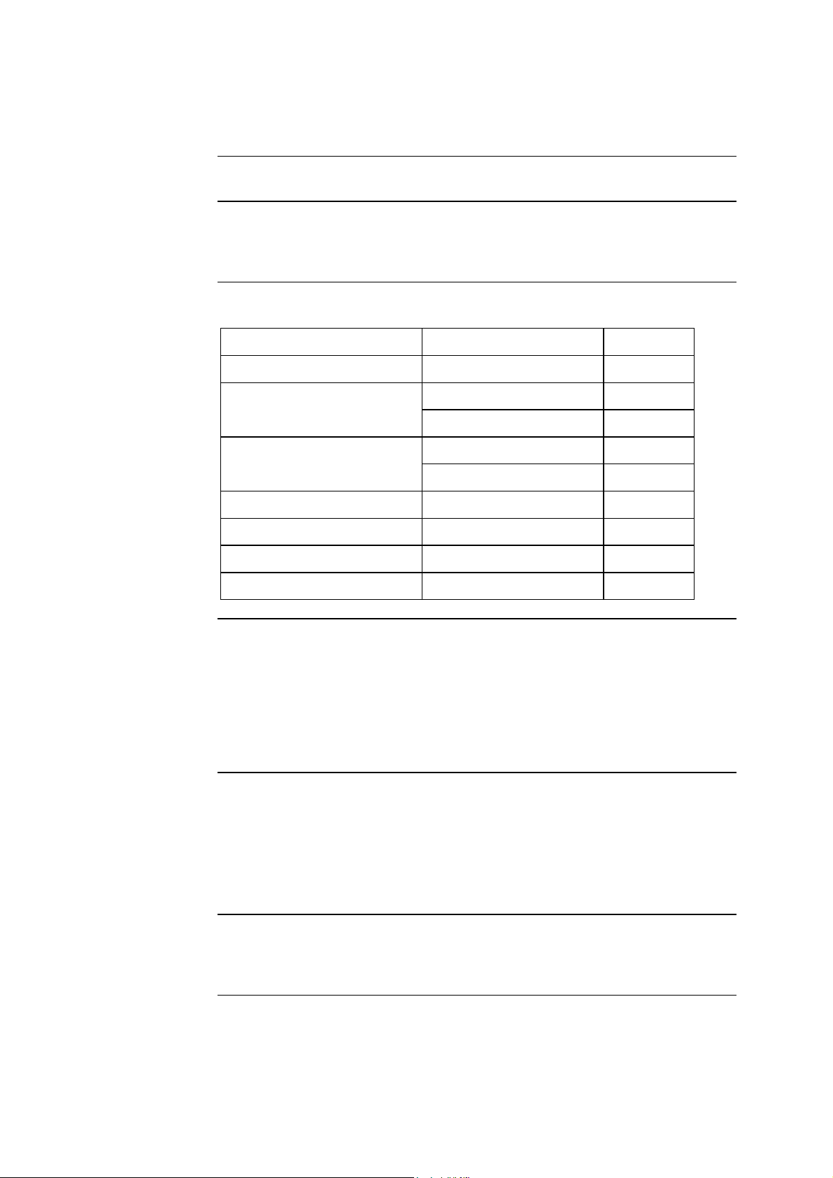
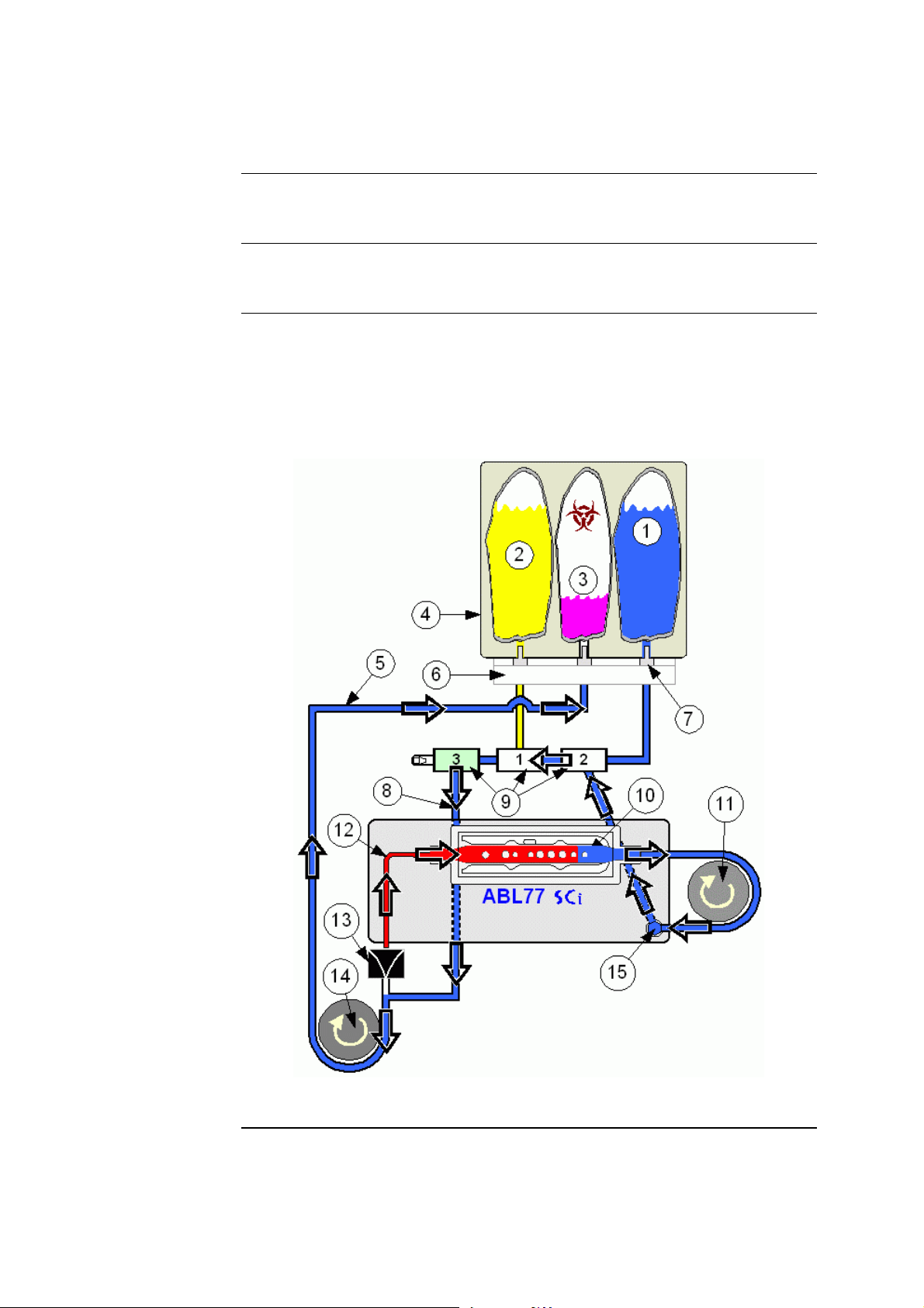
• During the first phase of the calibration process, the roller wheel is activated
along with valves 1 and 3. This flushes Cal2 solution through the sensor cassette
measuring chamber (see Figure 2-1).
• A measurement is then made on this solution.
• The waste pump is also activated to transport residual flush solution to the waste
pouch.
Figure 2-1
Continued on next page
2-6 Rev. F
Page 22

ABL77 Service Manual Chapter 2: Analyzer Description
Calibration, Continued
Calibrationphase 1
(continued)
Part Function
1. Cal1 solution (Calibration solution – Level 1)
2. Cal2 solution (Calibration solution – Level 2)
3. Waste bag
4. Cal Pack
5. Main waste line
6. Manifold
7. Manifold luers
8. Side waste line
9. Valves L1, L2 and L3
10. Cassette measuring chamber
11. Roller wheel
12. Inlet probe
13. Waste drain
14. Waste pump
15. Cassette luer
Continued on next page
Rev. F 2-7
Page 23
Chapter 2: Analyzer Description ABL77 Service Manual
Calibration, Continued
Calibration –
phase 2
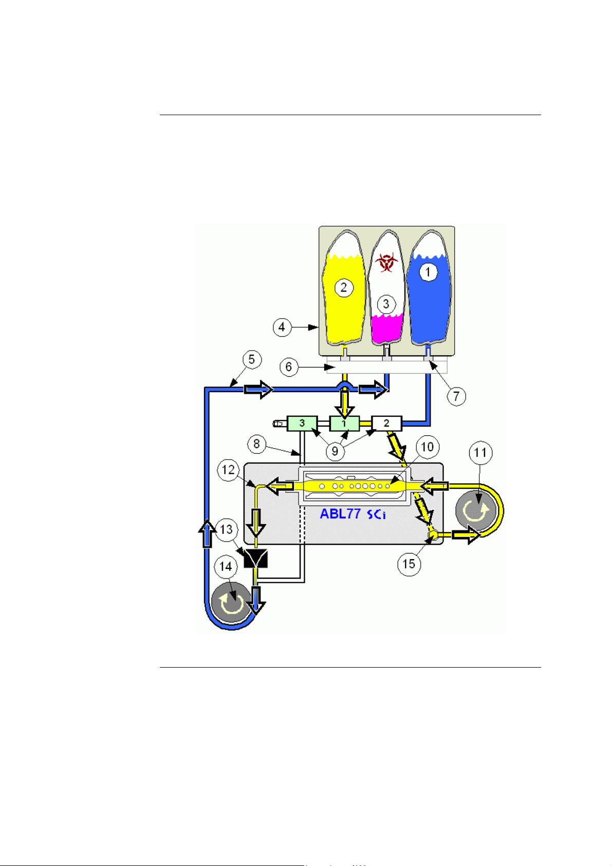
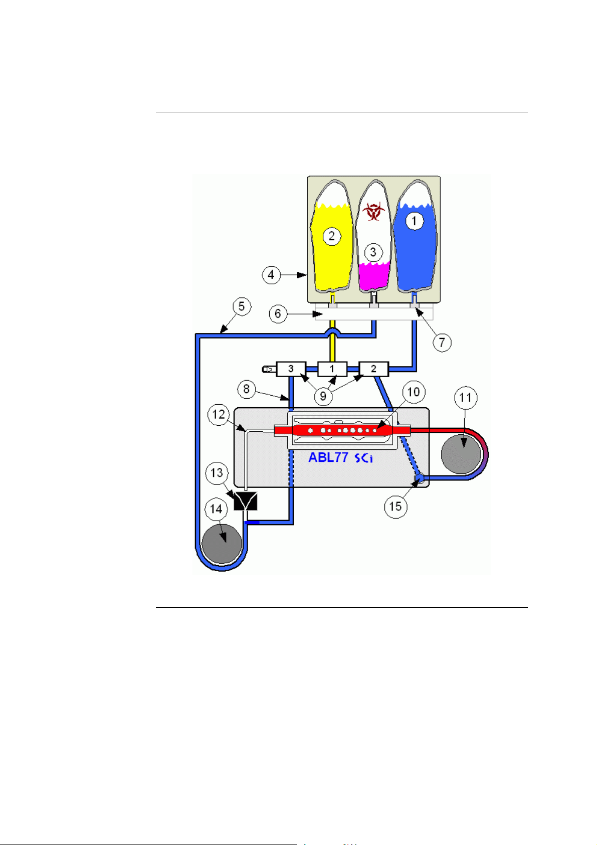
• During the second phase of the calibration, the roller wheel is activated along
with valves 2 and 3. This flushes Cal1 solution through the sensor cassette
measuring chamber (see Figure 2-2).
• A measurement is made on this solution.
• The waste pump is also activated to transport residual flush solution to the waste
pouch.
Figure 2-2
Continued on next page
2-8 Rev. F
Page 24

ABL77 Service Manual Chapter 2: Analyzer Description
Calibration, Continued
Calibration –
phase 2
(continued)
Part Function
1. Cal1 solution (Calibration solution – Level 1)
2. Cal2 solution (Calibration solution – Level 2)
3. Waste bag
4. Cal Pack
5. Main waste line
6. Manifold
7. Manifold luers
8. Side waste line
9. Valves L1, L2 and L3
10. Cassette measuring chamber
11. Roller wheel
12. Inlet probe
13. Waste drain
14. Waste pump
15. Cassette luer
Continued on next page
Rev. F 2-9
Page 25
Chapter 2: Analyzer Description ABL77 Service Manual
Calibration, Continued
Sensitivity
values
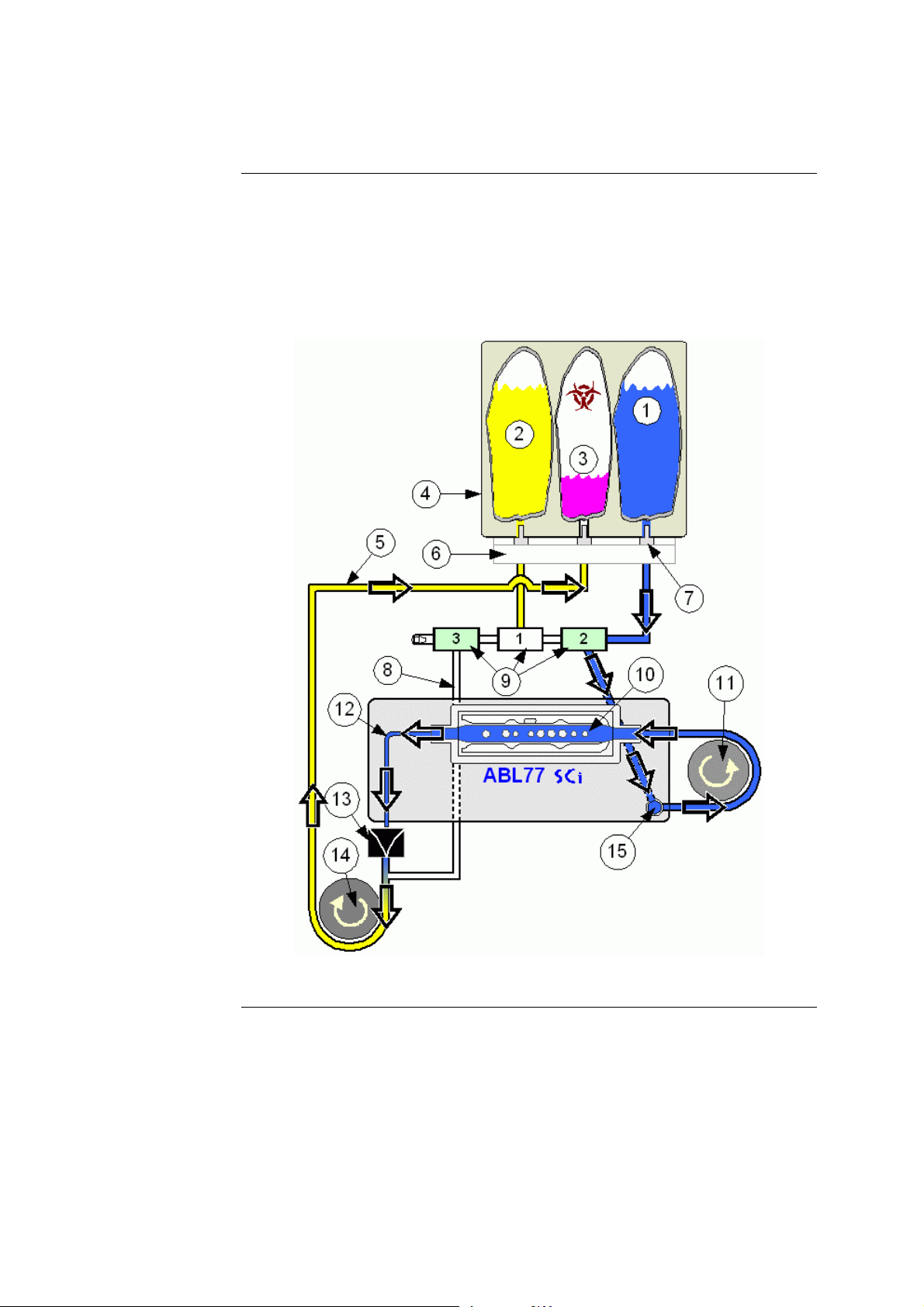
• Calibration sensitivity values are calculated based on these two measurements.
• These sensitivity values are compared to the acceptable range.
• If the values are acceptable, the calibration is complete.
• If one or more sensitivity values are outside the acceptable range, the
calibration is automatically repeated. If repeat calibration also results in one or
more parameter sensitivity values outside the acceptable range, the software
will suggest the appropriate next step. Suggestions include investigating the
fluidic pathways of the analyzer, inactivating the sensor, or replacing the
sensor cassette.
Parameter Acceptable Sensitivity Range
pH 40.0 – 61.5
CO2 30.0 – 61.5
Failed
calibration
status
O2 0.002 – 0.052
Na+ 40.0 – 61.5
K+ 40.0 – 61.5
Ca2+ 20.0 – 31.0
Cl– 30.0 – 61.5
Hct 10.0 – 25.0
If the calibration fails, the system will revert to a mandatory four-hour cycle of
two-point calibrations (without repeating) to maintain the fluidic system. A
successful calibration will return the analyzer to the calibration interval entered
into the Calibration Schedule.
2-10 Rev. F
Page 26

ABL77 Service Manual Chapter 2: Analyzer Description
This page intentionally left blank
Rev. F 2-11
Page 27
Chapter 2: Analyzer Description ABL77 Service Manual
Sample Analysis
Introduction
Analysis – initial
flush
Analysis – phase
1 aspiration
The Analysis option on the Main Menu allows the user to initiate a sample
analysis.
Pressing the Analysis icon initiates a brief flush of Cal1 solution to ensure the tip
of the inlet probe is filled with fluid.
• To begin the sample analysis, the inlet probe flap is lifted to the syringe or
capillary position.
• The Aspirate button is then pressed.
• The primary sample pump then draws in 70 microLiters of sample (see
Figure 2-3).
Figure 2-3
Continued on next page
2-12 Rev. F
Page 28

ABL77 Service Manual Chapter 2: Analyzer Description
Sample Analysis, Continued
Analysis – phase
1 aspiration
(continued)
Part Function
1. Cal1 solution (Calibration solution – Level 1)
2. Cal2 solution (Calibration solution – Level 2)
3. Waste bag
4. Cal Pack
5. Main waste line
6. Manifold
7. Manifold luers
8. Side waste line
9. Valves L1, L2 and L3
10. Cassette measuring chamber
11. Roller wheel
12. Inlet probe
13. Waste drain
14. Waste pump
15. Cassette luer
Continued on next page
Rev. F 2-13
Page 29
Chapter 2: Analyzer Description ABL77 Service Manual
Sample Analysis, Continued
Analysis – phase
2 aspiration
• The analyzer prompts the user to remove the sample and lower the inlet probe
• The analyzer then advances the sample a second time to complete the positioning
of the sample (see Figure 2-4).
Figure 2-4
Continued on next page
2-14 Rev. F
Page 30

ABL77 Service Manual Chapter 2: Analyzer Description
Sample Analysis, Continued
Analysis – phase
2 aspiration
(continued)
Part Function
1. Cal1 solution (Calibration solution – Level 1)
2. Cal2 solution (Calibration solution – Level 2)
3. Waste bag
4. Cal Pack
5. Main waste line
6. Manifold
7. Manifold luers
8. Side waste line
9. Valves L1, L2 and L3
10. Cassette measuring chamber
11. Roller wheel
12. Inlet probe
13. Waste drain
14. Waste pump
15. Cassette luer
Continued on next page
Rev. F 2-15
Page 31

Chapter 2: Analyzer Description ABL77 Service Manual
Sample Analysis, Continued
Analysis –
sample flush
• Following the sample measurement, the roller wheel is activated along with
valves 2 and 3 to flush cal 1 solution through the sensor cassette (see Figure 2-5).
• A measurement is performed using this cal solution prior to final results being
displayed ensuring that no drift has occurred.
• The waste pump is activated to transport the flush solution to the waste pouch.
Figure 2-5
Continued on next page
2-16 Rev. F
Page 32

ABL77 Service Manual Chapter 2: Analyzer Description
Sample Analysis, Continued
Analysis –
sample flush
(continued)
Part Function
1. Cal1 solution (Calibration solution – Level 1)
2. Cal2 solution (Calibration solution – Level 2)
3. Waste bag
4. Cal Pack
5. Main waste line
6. Manifold
7. Manifold luers
8. Side waste line
9. Valves L1, L2 and L3
10. Cassette measuring chamber
Quality control
11. Roller wheel
12. Inlet probe
13. Waste drain
14. Waste pump
15. Cassette luer
Routine quality control measurements are suggested to evaluate the performance of
the analyzer. This ensures the reliability, accuracy and precision of patient sample
results.
QC sample measurement follows similar steps as those used for blood sample
analysis.
Rev. F 2-17
Page 33

Chapter 2: Analyzer Description ABL77 Service Manual
Module Descriptions
Overview
ABL77 analyzer
Front view of
analyzer
This section describes the analyzer, individual modules and external components.
Detailed diagrams of the modules and connections are included with each module.
This sub-section describes the analyzer, external components and disposables.
Figure 2-6 shows the front view and sensor cassette of the ABL77 analyzer.
Figure 2-6
Part Function
1. Upper module
2. Sensor cassette
3. Lower module
Continued on next page
2-18 Rev. F
Page 34

ABL77 Service Manual Chapter 2: Analyzer Description
Module Descriptions, Continued
Rear view of
analyzer
Figure 2-7 shows the rear view and cal pack of the ABL77 analyzer.
Figure 2-7
Part Function
1. Main housing assembly
2. Cal pack
3. Electronics module
Continued on next page
Rev. F 2-19
Page 35

Chapter 2: Analyzer Description ABL77 Service Manual
Module Descriptions, Continued
Battery charger
The external battery charger is for use with the ABL77 analyzer only. It provides
the source of AC power to the system when plugged into an active electrical socket
(see Figure 2-8).
Battery pack
Figure 2-8
The battery pack is for use with the ABL77. It provides battery power to the
analyzer when AC power is not available or not desired (see Figure 2-9).
Figure 2-9
Continued on next page
2-20 Rev. F
Page 36

ABL77 Service Manual Chapter 2: Analyzer Description
Module Descriptions, Continued
Barcode scanner
The barcode scanner, shown below, is for use with the ABL77 analyzer only (see
Figure 2-10).
Barcode scanner
holder
Figure 2-10
The barcode scanner holder may be installed on the analyzer in any location that is
convenient (see Figure 2-11).
Figure 2-11
Continued on next page
Rev. F 2-21
Page 37

Chapter 2: Analyzer Description ABL77 Service Manual
Module Descriptions, Continued
Disposables
Sensor cassette
The ABL77 has two key disposable components, a sensor cassette and a cal pack.
These disposable items are designed for a limited number of uses throughout a
specified in-use life. After use, these components are considered a biohazard and
should be disposed of in a safe and proper manner.
The sensor cassette contains the sensor array within a sample flowcell. It transmits
sensor data to the analyzer for interpretation (see Figure 2-12).
Figure 2-12
Part Function
1. Sensor window
2. Peristaltic pump tube
3. Inlet flap
4. Inlet probe
5. Release latch
Continued on next page
2-22 Rev. F
Page 38

ABL77 Service Manual Chapter 2: Analyzer Description
Module Descriptions, Continued
Cal pack
The cal pack contains the solutions used to calibrate and flush the sensor cassette
(see Figure 2-13). The cal pack also contains a waste bag to collect all samples,
solutions and other fluids that are processed through the analyzer.
1
3
2
Figure 2-13
Part Function
1. Cal2 pouch
2. Cal1 pouch
3. Waste bag
Continued on next page
Rev. F 2-23
Page 39

Chapter 2: Analyzer Description ABL77 Service Manual
Module Descriptions, Continued
ABL77 block
diagram
Figure 2-14 displays the inter-connection of primary and secondary components of
the ABL77 analyzer.
Figure 2-14
2-24 Rev. F
Page 40

ABL77 Service Manual Chapter 2: Analyzer Description
This page intentionally left blank
Rev. F 2-25
Page 41

Chapter 2: Analyzer Description ABL77 Service Manual
Upper Module
Introduction
Components
This section provides a description of the upper module of the ABL77 analyzer.
The upper module contains the display components and disk drive (see the
following figures).
• Resistive Touch Screen: Located in front of the LCD display. It reacts to gentle
pressure from a finger or wand to supply the ABL77 with user input.
• LCD Display: This is a 640 x 480 resolution, backlit, VGA, color display used
as the primary method to provide display information to the user.
• Backlight Inverter Board: This board converts then supplies the power to the
LCD display and the backlight bulb.
• Diskette Drive: This drive is a standard 3.5 inch floppy drive for 1.44 M-byte
diskettes. Its primary use is to download records and settings, and is used to
upgrade software.
Continued on next page
2-26 Rev. F
Page 42

ABL77 Service Manual Chapter 2: Analyzer Description
Module Descriptions, Continued
Diagrams
Figure 2-15
Part Function
1. Upper housing
2. Disk drive
3. Disk drive cable
4. Touch screen cable
5. LCD display cable
6. Backlight inverter cable
7. Backlight inverter
8. Insulating tape
9. Housing bracket
10. Touch screen panel
11. LCD display
Continued on next page
Rev. F 2-27
Page 43

Chapter 2: Analyzer Description ABL77 Service Manual
Module Descriptions, Continued
Diagrams
(continued)
Figure 2-16
Continued on next page
2-28 Rev. F
Page 44

ABL77 Service Manual Chapter 2: Analyzer Description
Module Descriptions, Continued
Diagrams
(continued)
Part Function
1. Backlight inverter board screws
2. Insulating tape
3. Backlight inverter board
4. Housing screws
5. Housing bracket
6. Copper tape
7. Disk drive screws
8. Disk drive washers
9. Copper cloth tape
10. Disk drive
11. LCD display
12. Touch screen panel
13. Upper housing
Rev. F 2-29
Page 45

Chapter 2: Analyzer Description ABL77 Service Manual
Lower Module
Introduction
Components
This section provides a description of the lower module of the ABL77 analyzer.
The lower module contains the following components and related mechanisms.
• The Valve Board routes all fluids through a system of three 3-way valves. The
valve board contains the sensor cassette connector and connections to the analog
board, door sensor, roller pump and waste pump motor.
• The Printer allows printing of sample test and QC reports, using a roll of
thermal paper.
• The Roller Pump draws calibration solutions and other fluids into and out of the
sensor cassette in carefully controlled step increments for accurate placement of
fluids.
• The Waste Pump transports waste fluids from the waste drain to the waste
pouch in the cal pack.
• The Sensor Cassette Nest provides a cavity to accommodate the sensor cassette.
This nest contains the electrical and fluid connections for the sensor cassette,
allowing the analyzer to receive data from the sensor cassette and to move fluids
through the sensor cassette.
• The Manifold is the connection point between the valve board and the cal pack
and provides a fluid pathway. The manifold is considered a separate part from
the lower module but is identified here to show the proper tubing connections.
Continued on next page
2-30 Rev. F
Page 46

ABL77 Service Manual Chapter 2: Analyzer Description
Module Descriptions, Continued
Valve board
Layout of the Valve Board, REF: 902-812 (Figure 2-17).
J5
J5
12 1
13 24
J2
K1
J6
J6
J1
J3
SENSOR
LUER
41449 / B
SENSOR BOSS
L2 L1 L3
R2
R18
J4
J4
J9
J9
2587
PN 902-812
J8
41477
SERVICE BOARD ABL70-77
ASSY REV :
REVISION
J8
J10
J10
J7
J7
Figure 2-17
The Valve Board Assembly (REF: 902-811) includes the valves and tubing
(Figure 2-18).
J5
J5
12 1
13 24
J2
K1
J6
J6
J3
SENSOR
LUER
41449 / B
J1
COM
N.C.
SENSOR BOSS
N.O.
L2
L2 L1 L3
J4
J4
J9
J9
2587
R2
R18
PN 902-811
J8
Figure 2-18
COM
N.O.
41477
ASSY REV :
REVISION
N.C.
L3
COM
N.C.
L1
SERVICE BOARD AB L70-77
J8
N.O.
J10
J10
J7
J7
Continued on next page
Rev. F 2-31
Page 47

Chapter 2: Analyzer Description ABL77 Service Manual
Module Descriptions, Continued
Lower module Front
Figure 2-19
Part Function
1. Waste drain
2. Waste pump
3. Sensor cassette nest
4. Roller pump wheel
5. Printer
Continued on next page
2-32 Rev. F
Page 48

ABL77 Service Manual Chapter 2: Analyzer Description
Module Descriptions, Continued
Lower module Rear
Figure 2-20
Part Function
1. Printer
2. Sensor luer connector
3. Roller pump motor
4. I/O cable connector
5. Valve board
6. Sensor cable connector
7. Opto sensor
8. Manifold
9. Waste pump
Rev. F 2-33
Page 49

Chapter 2: Analyzer Description ABL77 Service Manual
Electronics Module
Introduction
Components
This section provides a description of the electronics module of the ABL77
analyzer.
• Electronics Boards
• Analog board
• Power distribution board
• Interface board
• ChipDisk
• LCD adapter board
• Memory module
• CPU board
• Touch screen controller board
• Battery control board
• Rear Panel with External Connections
• Barcode scanner / keyboard connector
• COM1 port
• Ethernet port
• Power switch
• Charger port
• Battery Pack
Continued on next page
2-34 Rev. F
Page 50

ABL77 Service Manual Chapter 2: Analyzer Description
Module Descriptions, Continued
Electronics Boards
Analog board
The analog board (REF: 902-682) contains a microprocessor and custom
algorithms that control valve, motor, and sensor operations (see Figure 2-21). The
onboard processor performs various operations such as thermistor control, roller
pump motor control, and sensor signal A to D conversions. This remote
intelligence enables the main computer to focus primarily on the operator interface.
Commands are received from the main computer to turn on valves, motors, begin
sensor heating cycle, etc. The analog board returns a character string once a second
to the main computer that contains the output states and sensor characteristics.
Figure 2-21
Continued on next page
Rev. F 2-35
Page 51

Chapter 2: Analyzer Description ABL77 Service Manual
Module Descriptions, Continued
Power
distribution
board
The power distribution board (REF: 902-838) receives power from the battery
control board and routes the power to the electronic boards assembly and the
analog board (see Figure 2-22).
Figure 2-22
Interface board
ChipDisk
The interface board (REF: 902-681) contains the internal speaker and the coin cell
battery that supplies the CPU with power to maintain the computer settings See
Figure 2-23). This board also receives signals from the barcode scanner and routes
data to the printer to produce reports.
SPK
BAT 1
SN
J3
Revision
ASSY 41407
Figure 2-23
The ChipDisk (REF: 365-436) is the mass storage media for all records, settings
and software (see Figure 2-24). It is an electronic based “computer hard drive” The
ChipDisk is a component of the CPU board.
Figure 2-24
Continued on next page
2-36 Rev. F
Page 52

ABL77 Service Manual Chapter 2: Analyzer Description
Module Descriptions, Continued
LCD adapter
board
Memory module
The LCD adapter board (REF: 902-678) converts signals from the CPU for use by
the LCD display (see Figure 2-25). The LCD adapter board is a component of the
CPU board.
Figure 2-25
The memory module (REF: 365-438) is the active memory (RAM) that the CPU
uses for calculations and command processing (see Figure 2-26). The memory
module is a component of the CPU board.
Figure 2-26
Continued on next page
Rev. F 2-37
Page 53

Chapter 2: Analyzer Description ABL77 Service Manual
Module Descriptions, Continued
CPU board
The CPU board (REF: 902-679) consists of a 486 SX microcomputer with at least
8 MB memory, VGA, serial and parallel ports, and floppy disk control (see
Figure 2-27). The interface board connects the microcomputer to its battery support
and speaker as well as interfacing with the printer and the COM 1 port. Valves,
motors, and sensor states are controlled by commands sent via the serial
connection to the custom analog board.
Touch screen
controller
Figure 2-27
The touch screen controller (REF: 365-437) processes all signals from the touch
screen and sends these signals to the CPU (see Figure 2-28).
Figure 2-28
Continued on next page
2-38 Rev. F
Page 54

ABL77 Service Manual Chapter 2: Analyzer Description
Module Descriptions, Continued
Battery control
board
The battery control board (REF: 902-680) monitors system power requirements
and diverts the incoming AC power to and from the battery pack accordingly (see
Figure 2-29). The batteries are charged in a controlled manner to prevent overcharging. The battery charge status is sent to the analog board and then
retransmitted to the main computer so that it can be displayed on the screen for the
operator.
J7
J1
R28
J5
U4/1
D7 D6
D1
U4/2
C2
U4/3
U4/4
J2
D2
R19
C1
R12
R23 R24
D9
J3
D10
D4 D3
U2
C13
R2
R21
R22
D5
C14 C15
R20
R9
Q6 Q5
P4
U1
R3
R4
R25
R6
R8
Q3Q4
R27
P5 P7 P6
P1
R5 R10
Q8 Q7
C8
R17
R11
R7
D11
R13
D14
C3
C7
R15
C9
D13
J
4
C5
Q1
R14
U5
C10 C11
D8
P8 P3 P2
U4/9
U4/8
U6
C4
U4/7
C12
U4/6
U4/5
J8J6
Q2
VB5
D12
R18
C6
U3
C19
U7
R1
ASSY 41174
Figure 2-29
Continued on next page
Rev. F 2-39
Page 55

Chapter 2: Analyzer Description ABL77 Service Manual
Module Descriptions, Continued
Electronics
module
assembly
Figure 2-30
Continued on next page
2-40 Rev. F
Page 56

ABL77 Service Manual Chapter 2: Analyzer Description
Module Descriptions, Continued
Rear Panel with External Connections
Diagrams
Figure 2-31
Part Function
1. Barcode / keyboard port cable
2. Power switch cable
3. Ethernet port cable
4. COM1 port cable
5. Fan assembly cable
Continued on next page
Rev. F 2-41
Page 57

Chapter 2: Analyzer Description ABL77 Service Manual
Module Descriptions, Continued
Diagrams
(continued)
Figure 2-32
Part Function
1. COM1 port
2. Barcode / keyboard port
3. Fan
4. Charger port
5. Ethernet port
6. Power switch
7. Battery door
Continued on next page
2-42 Rev. F
Page 58

ABL77 Service Manual Chapter 2: Analyzer Description
Module Descriptions, Continued
Barcode /
keyboard
connector
COM1 port
The barcode scanner port is a 5 pin DIN connector that sends the signals to the
interface board. This port is also used for connecting a keyboard to the analyzer for
testing purposes.
The COM1 port is a serial connection to the CPU board. It allows interaction with
external computers. The RS232 port contains 9 pins. The following table lists the
pin designations and transmission format.
Pin I/O Description
Ethernet port
1.
2.
3.
4.
◄
◄
►
►
5.
6.
7.
8.
9.
◄
►
◄
◄
DCD (Data Carrier Detect)
RX (Receive Data)
TX (Transmit Data)
DTR (Data Terminal Ready)
GND (Signal Ground)
DSR (Data Set Ready)
RTS (Request To Send)
CTS (Clear To Send)
RI (Ring Indicator)
— Connector
The Ethernet port is a connection to the CPU. It allows bi-directional
communication with external computer systems.
Power switch
The power switch is a 2-position switch that places the analyzer in either an On or
Standby mode. There is no Off mode as the analyzer is always charging when it is
connected to an AC power source.
Charger port
The charger port is a 6 pin DIN connector. It allows the ABL77 charger to supply
AC power to the battery control board.
Continued on next page
Rev. F 2-43
Page 59

Chapter 2: Analyzer Description ABL77 Service Manual
Module Descriptions, Continued
Battery Pack
Battery pack
The battery pack contains 12 nickel metal hydride (NiMH) cells (see Figure 2-33).
The pack has a nominal DC voltage of 14.4 and a rated capacity of 3.8 Ah. The
battery pack stores power for use by the analyzer when not connected to an AC
power source. After use, the battery pack should be disposed of in a safe and
proper manner consistent with disposal of any battery.
Charge cycle of
the battery pack
Battery pack
temperature
Figure 2-33
The analyzer controls the charge to the battery pack using a counter and charge
controller. The counter value is reflected in the value displayed in the Bat field on
the Hardware screen.
The input charge increments the charge counter, which reflects the charge capacity
of the pack. The charge rate is a function of the current control circuit. As the
battery charges, the current applied will decrease in proportion to the battery
voltage. As the battery voltage increases, the temperature of the pack increases.
This increased temperature increases the internal pressure of the cells, causing a
higher voltage across the pack. This results in varying charge rates based on the
charge state of the battery pack. To ensure maximum charging of the pack, the
charge controller (on the Battery Control Board) provides a six-hour charge cycle.
For safety purposes, the maximum allowed charge current is 650 mA.
The counter decrements based on the normal operation of the analyzer on battery
power. The counter also decrements based on the self-discharge rate of the battery
with storage and age. The self-discharge rate is accelerated with increased
temperatures.
The battery pack contains an internal safety switch that is triggered based on the
current output over time and monitored by an internal thermistor. This switch
prevents unsafe levels of operation. During charging, if the temperature of the
battery pack rises above 45°C, charging is terminated. In addition, there is an
integral temperature cutoff switch which opens if the pack reaches 70 ± 5 °C. If
this switch is triggered, the battery pack will no longer be operational.
Continued on next page
2-44 Rev. F
Page 60

ABL77 Service Manual Chapter 2: Analyzer Description
Module Descriptions, Continued
Optimal battery
pack life
The lifetime of a battery pack is affected by various conditions. Elevated
temperatures, long periods of inactivity and incomplete charging will diminish the
expected lifetime and operation of the battery pack.
NiMH batteries operate at their optimal capacity when regularly exercised and
allowed to discharge to a level other than full capacity. It is recommended that the
analyzer be operated on battery power routinely or at regular intervals to maintain
optimal performance of the battery pack
Rev. F 2-45
Page 61

ABL77 Service Manual Chapter 3: Troubleshooting
3. Troubleshooting
Overview
Introduction
Contents
This chapter provides troubleshooting information for errors or messages that may
occur during the operation of the ABL77 analyzer.
This chapter contains the following topics.
Overview............................................................................................... 3-1
General Information ........................................................................................ 3-2
Cautions and Warnings ......................................................................... 3-3
General Guidelines................................................................................ 3-4
Hardware Screen ................................................................................... 3-5
Reference Table of Problems, Causes and Corrective Actions .................... 3-8
Reference Table .................................................................................... 3-9
System Messages............................................................................................. 3-16
3-1
Page 62

Chapter 3: Troubleshooting ABL77 Service Manual
General Information
Introduction
This section provides information regarding cautions and warnings as well as
information on normal operation that can be fundamental to understanding error
conditions.
3-2
Page 63

ABL77 Service Manual Chapter 3: Troubleshooting
Cautions and Warnings
Introduction
WARNING/
CAUTION:
This topic emphasizes important safety issues. Please review before proceeding
with any troubleshooting steps.
WARNING: Always turn the power off and unplug the system when cleaning the
analyzer.
CAUTION: Always remember to exercise Universal Precautions when handling
contaminants and biohazardous materials (OSHA standard 1910.1030).
CAUTION: Be prepared to collect fluid flowing from open ports and luers when
flushing analyzer parts. Always exercise Universal Precautions when handling
contaminants and biohazardous materials.
CAUTION: Pushing the syringe plunger too hard can damage internal tubing
connections and cause leakage. When using syringes to clear path obstructions,
whether filled with air or liquid, very gently push the syringe plunger to avoid
detaching internal tube connections.
CAUTION: Do not inject solution or air into the cal pack ports. Injecting solution
or air into the cal pack will alter the calibrant values and may cause erroneous
measurements and/or failure messages.
CAUTION: The cal pack contains two calibration fluid pouches and a waste
pouch. With use, the waste pouch may contain blood and other biohazardous
fluids. Disposal of a used cal pack should comply with all required biohazard
regulations.
CAUTION: Dispose of used cal packs immediately. If immediate disposal is not
possible, lay the cal pack on its side or back and replace the foil cover over the
ports to prevent potentially contaminated ports from contacting other surfaces.
Laying a used cal pack on its side or back can also prevent leakage in the unlikely
event that a cal pack port develops a slight seepage.
3-3
Page 64

Chapter 3: Troubleshooting ABL77 Service Manual
General Guidelines
Introduction
Suggested tools
Warranty
sensor cassette
returns
This topic describes additional information pertinent to the use of the ABL77
analyzer.
• The following tools are recommended for various service procedures:
• A Sample Path Obstruction Tools (REF: 905-674) kit can assist in removing
fluid path obstructions.
• A Zeroing Cassette (REF: 902-578) is used to zero the sensor channels
• A Valve Board Calibration Cassette (REF: 920-729) is used to calibrate the
Hct and SC channels between the valve board and analog board.
Any sensor cassette that fails during use should be returned via the distributor to
SenDx Medical, Inc. Please return all the following items for full warranty credit
and to assist in a complete failure investigation:
Analyzer
component
returns
Cassette pump
tubing
• Sensor cassette
• Foil Pouch
• Printout of the failed Event Record. Only the Event Record contains a complete
set of information important for failure investigation. An Event Record is printed
from the Recall / Event screen.
• Highlight the failed calibration, initialization or QC analysis
• Press the
icon to print an Event Record of this failed event.
Any analyzer component returned for credit or for failure investigation should be
accompanied by a copy of the service work order. Please be as complete as
possible in describing the events that led up to the failure, any troubleshooting
steps taken, and resolution of the problem. Please include the serial number of the
analyzer repaired.
During calibrant pump cycles,
while the roller wheel is
spinning, the cassette pump
tubing can be "snapped"
repeatedly to help dislodge any
air bubbles residing in the
cassette tubing (see Figure 3-1).
This simple step can alleviate a
number of the more common
calibration and initialization
failure experiences.
Figure 3-1
3-4
Page 65

ABL77 Service Manual Chapter 3: Troubleshooting
Hardware Screen
Introduction
Description of
Hardware
screen
This topic describes the various features of the Hardware screen that can assist in
troubleshooting.
• The Hardware screen allows manual control of basic analyzer functions.
• The three soft keys across the bottom of the screen allow the user to initiate a
single flush of Cal1 solution, Cal2 solution, or a single aspiration through the
inlet probe (see Figure 3-2).
Figure 3-2
Continued on next page
3-5
Page 66

Chapter 3: Troubleshooting ABL77 Service Manual
Hardware Screen, Continued
Description of
Hardware
screen
(continued)
• Activate the heater circuit by selecting the check box labelled Heater ON (see
Figure 3-3). The temperature reading as measured by the thermistor (located in
the sensor cassette) is displayed and labelled Th.
Figure 3-3
• The oxygen sensor, which requires an applied current to function, can be
energized by selecting the check box labeled O2(nA).
• The Hematocrit sensors also require an applied current which is activated by
selecting the Hct(AD) choice on the drop-down menu which initially displays
OFF(AD).
• The other selection in this drop-down window refers to the air-in-sample circuit.
SC(AD) is the solution conductivity (SC) value. The units of measure for both
Hct and SC are analog to digital counts.
• The voltage output of the other sensors are displayed and labeled accordingly.
Continued on next page
3-6
Page 67

ABL77 Service Manual Chapter 3: Troubleshooting
Hardware Screen, Continued
Description of
Hardware
screen
(continued)
• A relative charge reading for the battery pack is displayed (Bat) as well as the
function of the battery charger (Pak) (see Figure 3-4). An inlet flap sensor
indicator is also displayed (Door).
Figure 3-4
3-7
Page 68

Chapter 3: Troubleshooting ABL77 Service Manual
Reference Table of Problems, Causes and
Corrective Actions
Introduction
This section summarizes, in table form, the various types of problems and error
conditions which may be encountered during the operation of the ABL77 analyzer.
3-8
Page 69

ABL77 Service Manual Chapter 3: Troubleshooting
Reference Table
Introduction
This table offers a convenient reference to problems, their causes and the
recommended corrective action.
The most frequent cause for each problem is listed first followed by less frequent
causes.
Problem Probable Cause Corrective Action
Calibration Failure – this also
includes failed initializations.
The important first step is to
identify whether the failure is
due to a sensor failure or failure
of the analyzer's fluidic system
Fluidic system blockage in
analyzer. This prevents fresh
calibration solution from
reaching the sensor array or
combines fresh cal solution with
air.
to properly transport the
calibration fluid to the sensor
cassette measuring chamber.
Follow the instructions on the
Sensor failure Inactivate the failed parameter
analyzer screen to help identify
the underlying cause.
Calibration, Initialization, or
QC failures with multiple sensor
Valve board – worn or corroded
pin receptacle
cassettes over time
Valve board – component
failure
Analog board – component
failure
Proceed to Chapter 4, Test and
Calibration Procedures to
investigate the fluidics system
using the Hardware screen and
the Calibration Lines procedure
or replace the SCi.
Replace the valve board.
Proceed to Chapter 5
Dismantling.
Replace the valve board.
Proceed to Chapter 5
Dismantling.
Replace the analog board.
Proceed to Chapter 5
Dismantling.
Zero calibration failure Check analyzer connector for
corrosion or wear. If OK,
proceed to Chapter 4, Test and
Calibration Procedures to set
the electronic zero of the sensor
channels.
Valve board - single valve
failure
Proceed to Chapter 4, Test and
Calibration Procedures to test
the valves on the valve board. If
a valve is malfunctioning,
replace it. See Chapter 6
Replacements.
Continued on next page
3-9
Page 70

Chapter 3: Troubleshooting ABL77 Service Manual
Reference Table, Continued
Problem Probable Cause Corrective Action
Calibration, Initialization, or
QC failures of the Hct channel
with multiple sensor cassettes
over time. Also multiple false
Insufficient 5V supply of power Proceed to Chapter 4, Test and
Calibration Procedures to
check the 5 volt power supply.
Adjust as necessary.
air-in-sample messages with
multiple sensor cassettes over
time
Calibration of SC/Hct circuit is
not possible. Unable to attain
target calibration values.
Insufficient 5V supply of power Proceed to Chapter 4, Test and
Calibration Procedures to
check the 5 volt power supply.
Adjust as necessary.
Computer – Incomplete bootup
CPU Board Malfunction Replace CPU Board. See
Chapter 5, Dismantling
Chip Disk Malfunction Replace Chip Disk. See Chapter
5, Dismantling
Computer – clock malfunction CPU Board Malfunction
(software versions 1.30 or
Replace CPU board. See
Chapter 5, Dismantling
lower)
Analog board real-time clock
malfunction or clock battery on
Replace analog board. See
Chapter 5, Dismantling
analog board depleted (software
versions 1.32 or higher)
Disk Drive
Disk drive failure Replace the disk drive. See
Chapter 5, Dismantling
Disk drive cable Check the connection. Replace
as necessary. See Chapter 6,
Replacements
Main CPU Replace the main CPU. See
Chapter 5, Dismantling
Floppy diskette damaged, full,
or has write-protect activated.
Leak – at manifold Worn manifold gasket. Can
cause fluid leakage into printer
area.
Use another diskette or
inactivate the write-protect.
Replace gasket. Refer to
specific instructions in Chapter
5, Dismantling. The first step is
to identify the correct version of
gasket that is being replaced.
Also, check the printer to ensure
there is no corrosion.
Continued on next page
3-10
Page 71

ABL77 Service Manual Chapter 3: Troubleshooting
Reference Table, Continued
Problem Probable Cause Corrective Action
Power – no AC power A/C not reaching the analyzer
due to poor power cord
connection or inactive power
Verify active power source and
ensure all cord connections are
secure
source
Battery charger malfunction See Battery Charger in Chapter
4. Replace as necessary.
Battery Control Board
malfunction
Replace the battery control
board. See Chapter 5,
Dismantling
Power – no battery power Battery Pack has aged Replace battery pack. See
Battery Pack in Chapter 4.
Battery Pack is not fully
See Battery Pack in Chapter 4
charged
Battery Charger malfunction See Battery Charger in Chapter
4. Replace as necessary
Power – intermittent power loss Battery Control Board
malfunction
Replace battery control board.
See Chapter 5, Dismantling
Printer – non functional Corrosion on printer module Replace printer module. See
Chapter 5, Dismantling.
Investigate source of fluid
contamination
Printer Board malfunction Replace board. See Chapter 5,
Dismantling
Printer Power Cable Check the connection. Replace
as necessary. See Chapter 6,
Replacements
Printer Data Cable Check the connection. Replace
as necessary. See Chapter 6,
Replacements
Thermal Printer malfunction Replace the thermal printer. See
Chapter 5, Dismantling
Continued on next page
3-11
Page 72

Chapter 3: Troubleshooting ABL77 Service Manual
Reference Table, Continued
Problem Probable Cause Corrective Action
Printer – Other
Printout light or missing pixels /
not sensing paper: the thermal
printer can have a component
malfunction or this problem can
be the result of corrosion
Printout light / poor quality:
thermal paper has been exposed
to high temperature
Printout is un-readable or
shows streaks: the printer data
cable pins are making contact
with the screw that holds the
printer module together.
Paper continually advances:
BIOS setting incorrect
No printout: The printer must be
enabled in the software.
Replace printer. See Chapter 5,
Dismantling. If corrosion is
present, investigate source of
fluid contamination
Use a fresh roll of thermal
paper.
Replace the metal screw with a
nylon screw (REF: 023-013).
See Chapter 5 - Printer Module
Reset the BIOS setting in the
main CPU. See Chapter 4, Test
and Calibration Procedures.
This option is under Manager
Setup/ Report Setup / Print
Setup. The auto print feature
must be selected for patient,
calibration, and QC
Paper Jam
Paper installed backwards
Paper shifts to the left: This is a
normal printer response when a
new roll of paper is installed
• See Chapter 4, Test and
Calibration Procedures
• Instruct user on proper steps
when replacing the paper roll
which includes:
• Advancing the leading edge
of the paper out the printer
door
• Ensuring the operator
removes paper by tearing up
or down, not sideways
Orient the paper correctly. Refer
to the diagram on the inner
surface of the printer door
Advancing the paper roll 18 to
24 inches (~0.5 meter) when
installing a new roll of paper
will allow the paper to seat itself
properly within the printer
3-12
Continued on next page
Page 73

ABL77 Service Manual Chapter 3: Troubleshooting
Reference Table, Continued
Problem Probable Cause Corrective Action
QC - results out of range
If failures are occurring with
multiple sensor cassettes over
time see "Calibration,
Initialization, or QC failures
Incorrect handling Review the user's QC technique.
Stress the importance of
thorough mixing and aspirating
the sample immediately after
opening.
with multiple sensor cassettes
over time"
Incorrect temperature of
ampoule
Equilibrate ampoule to a known
temperature. Ensure the correct
QC Temperature value is
entered into the analyzer
Incorrect ranges Use correct ranges. Ensure
proper ranges are entered into
analyzer
Incorrect lot Verify the proper lot of QC
material is being tested
Faulty sensor function
• Perform a manual calibration
and repeat the QC
measurement
• If QC fails repeatedly,
activate QC lockout,
inactivate parameter or
replace sensor cassette
Screen - blank/dark display
Description: the screen remains
dark and blank despite signs of
power (beeps, fan running etc)
LCD Display Cable Check the cable connection. If
securely connected, replace the
cable. See Chapter 6,
Replacements
Backlight Inverter Check the connection. If
securely connected, replace the
backlight inverter. See Chapter
5, Dismantling
LCD Adapter Board
malfunction
Replace the LCD Adapter
Board. See Chapter 5,
Dismantling
Screen - blank / illuminated
Description: the screen lights up
(glows but there is no text or
graphics)
The application software has not
successfully loaded due to a
CPU failure
LCD Adapter Board
malfunction
Replace the main CPU. See
Chapter 5, Dismantling
Replace the LCD Adapter
Board. See Chapter 5,
Dismantling
Continued on next page
3-13
Page 74

Chapter 3: Troubleshooting ABL77 Service Manual
Reference Table, Continued
Problem Probable Cause Corrective Action
Screen – Touch Screen non
functional
Description: there is no response
when the touch screen is pressed
Main CPU Replace the main CPU. See
Chapter 5, Dismantling
LCD Display Cable Check the connection. Replace
as necessary. See Chapter 6,
Replacements
Touch Screen Controller Board Replace the board. See Chapter
5, Dismantling
Touch Screen Panel malfunction Replace the panel. See Chapter
5, Dismantling
Touch Screen cable Check the connection. Replace
as necessary. See Chapter 6,
Replacements
Barcode scanner connection or
cable
Remove barcode scanner. Shut
down unit. Power up unit and
verify the touch screen is
operating correctly. If so,
reconnect barcode scanner and
verify the touch screen is still
operating correctly. If not,
replace the barcode scanner.
Screen – Touch Screen display
malfunction
Description: variety of incorrect
displays (e.g. missing pixels or
no text)
Screen – Touch Screen
Description: pressing in one
area of the screen produces an
effect on another area of the
screen
LCD Display Panel Replace the panel. See Chapter
5, Dismantling
LCD Display Cable Check the connection. Replace
as necessary. See Chapter 6,
Replacements
Screen is not properly calibrated Proceed to Chapter 4, Test and
Calibration Procedures to
recalibrate the touch screen.
Continued on next page
3-14
Page 75

ABL77 Service Manual Chapter 3: Troubleshooting
Reference Table, Continued
Problem Probable Cause Corrective Action
Temperature Errors
SCi temperature circuit failure Replace the sensor cassette. See
Chapter 4, Test and Calibration
Procedures for further
instructions on checking the
heater circuit
Valve Board - worn or corroded
pin receptacle
Analog Board - component
failure
Waste Drain – waste fluids
overflowing out the waste drain
Blockage in the waste drain
tubing
during flush cycles
Replace the valve board. See
Chapter 5, Dismantling
Replace the analog board. See
Chapter 5, Dismantling
Flush the waste drain. See
Waste Drain in Chapter 4
further in this chapter
Waste Pump Motor failure Replace the waste pump (a
"waste pump kit" includes the
motor and pump head). See
Chapter 5, Dismantling
Waste Pump head is worn Replace the waste pump head
Cal Pack waste port is blocked
Replace the cal pack
or pouch has been over-filled
3-15
Page 76

Chapter 3: Troubleshooting ABL77 Service Manual
System Messages
Introduction
System messages
Error # Message Interpretation Corrective Action
This section lists system messages, provides an interpretation and any
recommended corrective action. This section groups system messages in
categories. Reference error messages using its unique error number.
This table provides an interpretation of the message and suggests corrective action.
1000 System Errors
1001 Battery is low Battery voltage is below
minimum charge
Connect analyzer to A/C
power. If battery does not
re-charge refer to Chapter 4,
Test and Calibration
Procedures to test the
battery. Replace the battery
pack as necessary.
1002 Unable to allocate memory Insufficient memory Cycle the analyzer power
off then back on to re-boot
the computer.
1003 Calculation error Unable to calculate
sensitivity values due to
impossible mathematical
values
Repeat the measurement. If
this error persists,
investigate possible sources
of air contamination.
1004 The file can not be opened Memory is unavailable. Shutdown the analyzer
power through the Main
Menu Shutdown button
then turn the analyzer back
on to re-boot the computer
1005 A file has been corrupted The file being read has been
corrupted.
Investigate a possible main
CPU failure
1006 No data from analog board. The analyzer does not
recognize any signal from
the analog board
3-16
Check cable connections.
Replace the A/D ribbon
cable between the CPU and
analog board as necessary.
Secondarily it may be
necessary to replace the
Analog board.
Continued on next page
Page 77

ABL77 Service Manual Chapter 3: Troubleshooting
Reference Table, Continued
Error # Message Interpretation Corrective Action
1100 Printer Errors
1101 Printer access denied General failure of the
operating system.
Shutdown the analyzer
power through the Main
Menu Shutdown button
then turn the analyzer back
on to re-boot the computer
1102 The printer is out of paper. The printer sensor does not
recognize the presence of
paper
Load paper in the printer. If
the printer is not sensing the
presence of paper, replace
the printer
1103 The printer head is up. The print head lever is in the
Lower the print head lever.
up position, which lifts the
printer head off the paper.
1104 Printer Error Hardware Error Replace the printer module
1105 Printer Error Hardware Error Replace the printer module
1106 Printer Error Hardware Error Replace the printer module
1200 Detection Errors
1201 Warning! Possible air in
sample.
Air-in-sample detection
system has identified air in
the measuring chamber
during sample analysis. The
air may affect sample
Carefully evaluate sample
analysis results for integrity
and acceptable clinical
correlation. Repeat analysis
suggested.
results.
1202 Air in calibration fluid. Air-in-sample detection
system has identified air in
the measuring chamber
during the Cal1 phase of
sample analysis. The air
may affect sample result
calculations
1203 Air detection is unavailable
for this analysis.
Air-in-sample detection
circuit does not meet
stability requirements for
this analysis.
1204 Air detection is unavailable. Air-in-sample detection
circuit has malfunctioned or
is unable to determine
reference point due to air in
calibration fluid prior to
analysis.
Carefully evaluate sample
analysis results for integrity
and acceptable clinical
correlation. Perform a
manual calibration and
repeat the sample analysis.
Perform a manual
calibration and repeat the
sample analysis.
• Perform a manual
calibration and repeat the
sample analysis
• If the condition persists,
re-install the current
sensor cassette
Continued on next page
3-17
Page 78

Chapter 3: Troubleshooting ABL77 Service Manual
Reference Table, Continued
Error # Message Interpretation Corrective Action
1300 Sensor Errors
1301 Sensor cassette is not
connected.
Analyzer does not sense the
presence of a sensor cassette
1302 Sample inlet flap is open The analyzer is preparing to
flush and the inlet probe is
not down
1303 Sensor cassette not
initialized.
The analyzer has not
successfully installed a
sensor cassette either
because the initialization
process was not performed,
was not allowed to be
completed, or because the
initialization was not
successful.
Re-seat sensor cassette. If
message persists after reseating try another sensor
cassette. If message
continues, replace the valve
board
Lower the sample inlet flap.
If the inlet flap message
persists with the flap down,
refer to Chapter 4, Test and
Calibration Procedures to
investigate the opto sensor.
Complete the initialization.
If a failure occurs,
investigate the origin of the
failure. The important first
step is to identify whether
the failure is due to a sensor
failure or failure of the
analyzer's fluidic system to
properly transport the
calibration fluid to the
sensor cassette measuring
chamber See Hardware and
Calibration Lines in Chapter
4 Test and Calibration
Procedures.
1304 Sensor cassette has expired. The currently installed
sensor cassette is beyond its
in-use life or the cassette
being installed is expired.
1305 No reportable parameters All parameters have been
inactivated or all active
parameters are locked out
due to the QC lockout
feature.
3-18
Replace the sensor cassette
Re-activate desired
parameters under Active
Parameters, perform
successful QC analysis, or
turn off the QC lockout
feature, as applicable.
Continued on next page
Page 79

ABL77 Service Manual Chapter 3: Troubleshooting
Reference Table, Continued
Error # Message Interpretation Corrective Action
1306 QC Level 1 is required
before analysis can be
performed
QC Level 2 is required
before analysis can be
performed
QC Level 3 is required
before analysis can be
performed
QC Level 4 is required
before analysis can be
performed
QC Hct Level 1 is required
before analysis can be
performed
Mandatory QC interval has
been reached. Analysis will
not be allowed until
BG/Lytes QC Level 1
analysis is performed
Mandatory QC interval has
been reached. Analysis will
not be allowed until
BG/Lytes QC Level 2
analysis is performed.
Mandatory QC interval has
been reached. Analysis will
not be allowed until
BG/Lytes QC Level 3
analysis is performed.
Mandatory QC interval has
been reached. Analysis will
not be allowed until
BG/Lytes QC Level 4
analysis is performed.
Mandatory QC interval has
been reached. Analysis will
not be allowed until Hct QC
Level 1 analysis is
performed.
Perform the required
BG/Lytes QC measurement
or inactivate the required
QC interval
Perform the required
BG/Lytes QC measurement
or inactivate the required
QC interval.
Perform the required
BG/Lytes QC measurement
or inactivate the required
QC interval.
Perform the required
BG/Lytes QC measurement
or inactivate the required
QC interval.
Perform the required Hct
QC measurement or
inactivate the required QC
interval.
QC Hct Level 2 is required
before analysis can be
performed
Mandatory QC interval has
been reached. Analysis will
not be allowed until Hct QC
Level 2 analysis is
performed.
1308 No tests remaining. All allowable sample
analyses for the current
sensor cassette have been
performed.
1309 Hct: No End Point Stabilization criteria not met
for Hct
1310 This cassette has already
been installed. Please install
a new sensor cassette.
The sensor cassette has been
identified as previously
installed.
Perform the required Hct
QC measurement or
inactivate the required QC
interval.
Replace the sensor cassette.
Repeat measurement. If
message persists, inactivate
Hct or replace sensor
cassette.
Install a new sensor cassette.
Continued on next page
3-19
Page 80

Chapter 3: Troubleshooting ABL77 Service Manual
Reference Table, Continued
Error # Message Interpretation Corrective Action
1311 Calibration required before
analysis.
Maximum allowable time
between calibrations has
been reached.
1312 QC Level 1 out of range At least one parameter fell
outside the acceptable range
for the most recent
BG/Lytes Level 1 QC
measurement
QC Level 2 out of range At least one parameter fell
outside the acceptable range
for the most recent
BG/Lytes Level 2 QC
measurement
QC Level 3 out of range At least one parameter fell
outside the acceptable range
for the most recent
BG/Lytes Level 3 QC
measurement
Perform manual calibration
or allow auto calibration to
complete.
• Perform a manual
calibration and repeat the
BG/Lytes Level 1
measurement
• If results remain out of
range inactivate this
parameter or replace the
sensor cassette.
• Perform a manual
calibration and repeat the
BG/Lytes Level 2
measurement
• If results remain out of
range inactivate this
parameter or replace the
sensor cassette.
• Perform a manual
calibration and repeat the
BG/Lytes Level 3
measurement
• If results remain out of
range inactivate this
parameter or replace the
sensor cassette.
QC Level 4 out of range At least one parameter fell
outside the acceptable range
for the most recent
BG/Lytes Level 4 QC
measurement
3-20
• Perform a manual
calibration and repeat the
BG/Lytes Level 4
measurement
• If results remain out of
range inactivate this
parameter or replace the
sensor cassette.
Continued on next page
Page 81

ABL77 Service Manual Chapter 3: Troubleshooting
Reference Table, Continued
Error # Message Interpretation Corrective Action
1312
continued
QC Hct Level 1 out of range At least one parameter fell
outside the acceptable range
for the most recent Hct
Level 1 QC measurement
QC Hct Level 2 out of range At least one parameter fell
outside the acceptable range
for the most recent Hct
Level 2 QC measurement
1400 Calibration Errors
1407 Initialization failed At least one sensitivity value
is outside the acceptable
range during a cassette
initialization
• Perform a manual
calibration and repeat the
Hct Level 1 measurement
• If results remain out of
range inactivate this
parameter or replace the
sensor cassette.
• Perform a manual
calibration and repeat the
Hct Level 2 measurement
• If results remain out of
range inactivate this
parameter or replace the
sensor cassette.
Follow the instructions on
the screen. Investigate the
origin of the failure. The
important first step is to
identify whether the failure
is due to a sensor failure or
failure of the analyzer's
fluidic system to properly
transport the calibration
fluid to the sensor cassette
measuring chamber
1408 Calibration failed At least one sensitivity value
is outside the acceptable
range during a calibration
Follow the instructions on
the screen. Investigate the
origin of the failure. The
important first step is to
identify whether the failure
is due to a sensor failure or
failure of the analyzer's
fluidic system to properly
transport the calibration
fluid to the sensor cassette
measuring chamber
Continued on next page
3-21
Page 82

Chapter 3: Troubleshooting ABL77 Service Manual
Reference Table, Continued
Error # Message Interpretation Corrective Action
1500 Cal Pack Errors
1501 Cal pack not installed. There is no currently
installed cal pack on the
analyzer
1502 Cal pack has expired. The currently installed cal
pack is beyond its in-use
life.
1503 Cal 1 is empty. The current cal pack has
consumed all available Cal 1
solution.
1504 Cal 2 is empty. The current cal pack has
consumed all available Cal 2
solution.
1505 This cal pack has already
been installed. Please install
a new cal pack.
1506 Cal pack creation date is a
future date
The cal pack being installed
has previously been
installed.
The date the cal pack was
manufactured is a date in the
future
1507 Insufficient Cal1 cycles There are not enough Cal1
cycles remaining to ensure
completion of the desired
action
Install a new cal pack.
Install a new cal pack.
Replace the cal pack.
Replace the cal pack.
Install a new cal pack.
Check the accuracy of the
date in the analyzer.
Replace the cal pack
1508 Insufficient Cal2 cycles There are not enough Cal2
cycles remaining to ensure
completion of the desired
action
Replace the cal pack
Continued on next page
3-22
Page 83

ABL77 Service Manual Chapter 3: Troubleshooting
Reference Table, Continued
Error # Message Interpretation Corrective Action
1600 Temperature Errors
1601 Sample: Temperature Not
Stable
Temperature stabilization
criteria not met during
sample analysis
1602 Flush: Temperature Not
Stable
Temperature stabilization
criteria not met during
sample flush
1603 QC Sample: Temperature
Not Stable
Temperature stabilization
criteria not met during QC
sample analysis
1604 QC Flush: Temperature Not
Stable
Temperature stabilization
criteria not met during QC
sample flush.
1605 Cal 1: Temperature Not
Stable
Temperature stabilization
criteria not met during Cal 1
measurement
1606 Cal 2: Temperature Not
Stable
Temperature stabilization
criteria not met during Cal 2
measurement
1700 Upload Errors
1701 Connection timed out Maximum time exceeded for
uploading data to remote
host computer
See Chapter 4, Test and
Calibration Procedures to
investigate the heater circuit
See Chapter 4, Test and
Calibration Procedures to
investigate the heater circuit
See Chapter 4, Test and
Calibration Procedures to
investigate the heater circuit
See Chapter 4, Test and
Calibration Procedures to
investigate the heater circuit
See Chapter 4, Test and
Calibration Procedures to
investigate the heater circuit
See Chapter 4, Test and
Calibration Procedures to
investigate the heater circuit
Check connections. Verify
the remote host system is
working properly.
1702 Receiver not ready Remote host system has not
acknowledged it is ready to
receive data.
1703 Receiver cancelled Remote host system has
cancelled the
communication.
Wait a few moments then
retry. If problem persists,
verify the remote host
system is working properly
Wait a few moments then
retry. If problem persists,
check connections. Verify
the remote host system is
working properly.
Continued on next page
3-23
Page 84

Chapter 3: Troubleshooting ABL77 Service Manual
Reference Table, Continued
Error # Message Interpretation Corrective Action
1704 Session terminated The analyzer terminated the
upload session due to
unsuccessful transmission
after 6 attempts
1705 Receiver was not found Communication signal was
sent from the analyzer but
the remote host system was
not found
1706 The network settings are
invalid
• The network address
entered is not valid
• The address already exists
in the system
• Using DHCP and the
system was not connected
when turned on so an IP
address was not
automatically assigned
Check connections. Verify
the remote host system is
working properly.
• Verify the proper host
address or name and port
number in
Communications Setup
• Verify proper operation of
the remote host system
• Review the addresses
entered into the analyzer
and remote host system
• If using DHCP, check the
connections and re-boot
• If using a Computer
Name, check the integrity
of the connection (it is not
necessary to re-boot)
• Using a Computer Name
and the system was not
connected so this name
could not be interpreted as
an IP address
1707 Network error A general hardware or
software related problem
1708 Query failed The patient query found no
matches within the queried
external database
1709 This query command is not
enabled on Radiance
This query feature in
Radiance must be enabled
• Evaluate the status of the
remote host system
• Shutdown the analyzer
power through the Main
Menu Shutdown button
then turn the analyzer
back on to re-boot the
computer
• If it persists, contact your
IT resource
• Check the data input for
accuracy
• Execute an internal
database search
Enable the external query
command in Radiance.
3-24
Continued on next page
Page 85

ABL77 Service Manual Chapter 3: Troubleshooting
Reference Table, Continued
Error # Message Interpretation Corrective Action
1710 Internal query failed The patient query found no
matches within the
analyzer's database
1711 Connection terminated by
user
1712 No connection license
available
The external query was
cancelled by the user
The connection license has
not been acquired
1713 Wrong RAML version There is an incompatible
RAML version being used
in the Radiance
communication
1800 System Errors
1801 Analyzer has been locked The analyzer is in a locked
condition
Check the data input for
accuracy
Check the network load for
excessive delays
Contact the Radiometer
Sales Representative
Review the RAML version
and contact the appropriate
Radiance representative to
install a compatible version.
The system can be unlocked
either on the analyzer
(Options / Data
Communications /
Analyzer Lock) or if
connected to Radiance the
system can be unlocked
within Radiance (see
Analyzer Control).
3000 Input Errors
3001 Input error The value(s) input are
beyond the acceptable input
range.
3002 Invalid password Password entered was not
found in the User List
3003 Sensor cassette model is
incompatible with the
analyzer parameter
configuration.
A sensor cassette is being
installed with a parameter
configuration incompatible
with the analyzer's allowable
parameters.
3004 Data Bits can not be set to 5
while the Stop bits is set to
2.
Under Communication
Setup, only certain
combinations of data bits
and stop bits can be selected.
Re-enter values within the
acceptable input range.
Re-enter password. If
problem persists, review
password list and add
password as appropriate.
Install the correct model of
sensor cassette, matching it
with the analyzer
configuration.
Select the proper
combination of data bits to
stop bits
Continued on next page
3-25
Page 86

Chapter 3: Troubleshooting ABL77 Service Manual
Reference Table, Continued
Error # Message Interpretation Corrective Action
3005 Data bits can not be set to 6,
7, or 8 while the Stop bits is
set to 1.5.
Under Communication
Setup, only certain
combinations of data bits
and stop bits can be selected.
3006 Please select the settings
you wish to transfer.
Under Settings Transfer, the
user must select at least one
setting to transfer
3007 Order date cannot be a
future date.
Order Date field under
Patient Information had a
date entered that is beyond
the current date.
3008 Invalid bar code The bar code has been
entered in an unacceptable
format.
3011 Incorrect barcode scanned The barcode scanned is not
for the ABL77,
3012 Bar code scan unsuccessful The scanning process did
not result in a complete bar
code scan.
Select the proper
combination of data bits to
stop bits.
Select at least one setting
before attempting to transfer
settings.
Re-enter the correct order
date. If necessary, verify the
correct current date on the
analyzer.
Re-enter the bar code
correctly.
Ensure you are scanning the
ABL77 (not ABL70)
barcode on the cal pack.
Re-scan the barcode. Ensure
you are scanning the proper
bar code and the red scan
light covers all barcode
lines.
3013 Invalid solution ID The Radiometer solution ID
within the QC barcode is not
compatible for use with the
ABL77.
3014 Password Expired The user password has
expired.
Ensure you are using the
correct quality control
material and scanning the
correct, associated bar code.
Reset the user password in
the User Setup screen.
Continued on next page
3-26
Page 87

ABL77 Service Manual Chapter 3: Troubleshooting
Reference Table, Continued
Additional
messages
This table provides an interpretation of additional messages that may appear.
Message Interpretation Corrective Action
I/A Parameter is inactive. Turned off
by user.
L/O Parameter locked out due to QC
results outside acceptable limits.
N/A Not applicable. Appears in the
Hct field when Other Fluids is
selected for sample type.
N/D Parameter not derived because
measurement parameters
necessary for this calculation are
not available.
N/E No endpoint. Stabilization criteria
not met for one or more
parameters during sample
measurement or calibration.
N/I Not installed. A BG/Hct – only or
Lytes – only sensor cassette has
been installed on a full panel
analyzer.
No action required.
Perform a successful QC
measurement or deactivate the
QC lockout feature.
If Hct results are desired, repeat
the analysis selecting any sample
type other than Other Fluids.
Activate necessary measured
parameters or select necessary
measured parameters for
reporting.
No endpoints suggest air in the
measuring chamber. Investigate
possible sources of air. Then
perform a manual calibration and
repeat the measurement.
If all parameters are desired,
install a full panel sensor cassette.
N/R Not reported. This parameter was
not selected for reporting by the
user.
N/C Not calculated. Hct cannot be
calculated due to a failed Na+
calibration
*** Measured parameter value is out
of the analyzer display range.
# # # Sensor response is out of the
established response range.
Select all desired parameters from
the parameter profile and repeat
the analysis.
Repeat the calibration. If the
Na
+
failure persists, either continue
testing without Hct or replace the
sensor cassette.
Evaluate the integrity of the
sample. Perform a manual
calibration and repeat the sample
analysis.
Initiate a manual calibration.
Repeat the sample analysis.
Continued on next page
3-27
Page 88

Chapter 3: Troubleshooting ABL77 Service Manual
Reference Table, Continued
Additional
messages
(continued)
Message Interpretation Corrective Action
The sample analysis result is
above or below the user-defined
No action required for sample
analysis.
reference value.
The quality control result is above
or below the acceptable QC
range.
The sample analysis result has
fallen into the user-defined
critical range.
The sample analysis result has
fallen outside the reportable
range.
? Air was detected in the sample or
the associated sample flush
solution.
The last QC measurement for this
parameter was not acceptable.
The QC Lockout feature was not
activated
Perform a manual calibration then
repeat the QC measurement.
No action required.
Repeat the analysis if appropriate.
If air was detected in the sample,
repeat the analysis. If air is
detected in the flush solution,
perform a manual calibration then
repeat the analysis.
Perform a successful QC
measurement for the failed
parameter and level.
3-28
Page 89

ABL77 Service Manual Chapter 4: Test and Calibration Procedures
4. Test and Calibration Procedures
Overview
Introduction
WARNING/
CAUTION:
This chapter details the procedures for checking and adjusting the analyzer
circuitry.
The tools required for carrying out the procedures are listed in Chapter 1; Test
Equipment and Tools.
CAUTION: Follow legal requirements and local rules for safe work practices with
chemicals.
CAUTION: Working with blood gas analyzers may result in contact with blood
remnants and with harsh disinfectants. During the various procedures wear suitable
protection gear (gloves, face protection, and protective body clothing), following
legal requirements and local rules for safe work practices.
CAUTION: The gloves must be free of pinholes and preferably be puncture
resistant. Please consult the glove manufacturer for further information.
CAUTION: If contaminated material comes into contact with any lesion on the
body, seek medical advice.
Continued on next page
Rev. F 4-1
Page 90

Chapter 4: Test and Calibration Procedures ABL77 Service Manual
Overview, Continued
Contents
This chapter contains the following topics.
Electrostatic
discharge
protection
Overview............................................................................................... 4-1
Verify the Fluid Transport System........................................................ 4-3
Calibration Lines Procedure.................................................................. 4-5
Testing the Valve Connections ........................................................... 4-11
Valve Test Procedures......................................................................... 4-13
Check Valve Fluidics System ................................................ 4-15
Original Fluidics System........................................................ 4-19
Waste Line .......................................................................................... 4-26
5 Volt Power Output Setting............................................................... 4-29
SC/Hematocrit Circuits ....................................................................... 4-31
Electronic Zero Offset......................................................................... 4-34
Heater Circuit...................................................................................... 4-36
Inlet Flap Sensor ................................................................................. 4-39
Paper Jam ............................................................................................ 4-40
Battery Charger ................................................................................... 4-43
Battery Pack ........................................................................................ 4-45
Touch Screen Panel Calibration.......................................................... 4-48
Reprogramming the CPU BIOS Settings............................................ 4-50
Re-programming the Barcode Scanner ............................................... 4-52
Resetting the Analyzer Serial Number................................................ 4-56
To ensure the reliability and durability of the analyzer, ESD protection precautions
must always be taken when handling or exposing ESD sensitive parts. Parts such as
printed circuit boards may be damaged if handled incorrectly during storage and
service. The damage is not visible, and the damaged parts may not fail immediately
and can take up to several months before damage is apparent.
Calibration and
measurement
4-2 Rev. F
While performing certain calibrations and measurements, the analyzer must be
fully assembled. A cal pack and sensor cassette may be required.
Page 91

ABL77 Service Manual Chapter 4: Test and Calibration Procedures
Verify the Fluid Transport System
Introduction
Verify the
fluidics system
The Hardware screen may be used to manually initiate fluidic events. Observing
these events can help identify whether the analyzer’s fluidic system is effectively
transporting calibration fluids from the cal pack to the sensor cassette measuring
chamber.
Follow the steps below to verify proper flow of calibration fluids.
Step Action
Ensure a cal pack and a sensor cassette are installed on the analyzer.
1.
2.
• Select Options from the Main Menu
• Enter a Password that will allow access to the Hardware screen.
Access to this screen requires a password. If a user password is not
available, the generic MK592 may be used.
NOTE: This password is for Radiometer use only. Do not share
this password with customers.
• Select Hardware from the Options menu.
RESULT: The following screen will appear.
Press the Aspirate button to draw air into the sensor cassette
3.
measuring chamber.
• Carefully observe the measuring chamber. Ensure you can
recognize the different visual characteristics of the measuring
chamber when filled with fluid versus air.
Continued on next page
Rev. F 4-3
Page 92

Chapter 4: Test and Calibration Procedures ABL77 Service Manual
Verify the Fluid Transport System, Continued
Verify the
fluidics system
(continued)
Step Action
Press the Pump Cal1 button to flush Cal1 solution through the
4.
measuring chamber.
• Carefully observe the measuring chamber. The chamber should be
completely filled with fluid. There should be no air bubbles of any
size.
• If air is observed, flush Cal1 solution a second time. While the
pump wheel is turning, snap repeatedly on the pump tubing to
dislodge any air bubbles in the system.
• If fluid is being transported, it is also possible to see the fluid
dripping from the tip of the inlet probe down into the waste
receptacle.
Press the Aspirate button a second time to remove all Cal1 solution
5.
Press the Pump Cal2 to flush Cal2 solution through the measuring
6.
chamber.
• Carefully observe the measuring chamber. The chamber should be
completely filled with fluid. There should be no air bubbles of any
size.
• If air is observed, flush Cal2 solution a second time. While the
pump wheel is turning, snap repeatedly on the pump tubing to
dislodge any air bubbles in the system.
7.
• If both Cal1 and Cal2 solution fill the measuring chamber without
air, the fluid transport is functioning properly
• If one or both Cal solutions are mixed with air or do not flow at all,
continue to investigate the fluidic transport system. This includes
investigating:
• The cal pack. Ensure it is properly seated on the manifold and
has not been installed on more than one analyzer. Installing a
cal pack on multiple analyzers will cause inaccurate tracking
of cal cycles and cause cal solutions to be completely depleted
without warning.
• The sensor cassette. Ensure it is properly seated onto the
analyzer and free of blockage
• The internal fluidic pathways. To check, perform the
following Calibration Lines procedure.
4-4 Rev. F
Page 93

ABL77 Service Manual Chapter 4: Test and Calibration Procedures
Calibration Lines Procedure
Introduction
Calibration lines
procedure
The Calibration Lines procedure is used to evaluate the function of the internal
tubing and valves that are used to transport calibration solution from the cal pack to
the sensor cassette measuring chamber. If the calibration lines cannot be flushed,
one or more valves may be functioning improperly.
Follow the steps below to perform the Calibration Lines procedure.
Step Action
Select Options from the Main Menu.
1.
2.
• Enter a Password as necessary.
• Press OK.
Press Fluidics.
3.
RESULT: The following screen will appear.
4.
• From the pop-up window press Calibration Lines.
• Press Yes to continue.
Continued on next page
Rev. F 4-5
Page 94

Chapter 4: Test and Calibration Procedures ABL77 Service Manual
Calibration Lines Procedure, Continued
Calibration lines
procedure
(continued)
Step Action
If a sensor cassette is…
5.
Attached
The analyzer will remove any fluid, then prompt
the operator to remove the sensor cassette. The
analyzer will sense when the cassette has been
removed and will automatically proceed to the
next screen.
not attached
The analyzer will automatically proceed to the
next step.
RESULT: The following screen will appear.
Ensure there is a cal pack on the analyzer to collect the fluids exiting
6.
the waste line.
Introduce 1 cc of Cleaning Solution (REF: 943-906) into the waste
7.
drain (black opening located directly below the inlet probe when a
cassette is in place).
Continued on next page
4-6 Rev. F
Page 95

ABL77 Service Manual Chapter 4: Test and Calibration Procedures
Calibration Lines Procedure, Continued
Calibration lines
procedure
(continued)
Step Action
8.
• Activate the waste pump by pressing Pump. This will clear the
fluid, carrying it through the waste line and into the cal pack.
• Press Continue.
RESULT: The following screen will appear.
9.
Remove the cal pack and press Continue.
10.
CAUTION: The cal pack must
be removed before proceeding.
Performing the following steps with a cal pack in place will result in
contamination of the calibration solution.
RESULT: The following screen will appear.
11.
Continued on next page
Rev. F 4-7
Page 96

Chapter 4: Test and Calibration Procedures ABL77 Service Manual
Calibration Lines Procedure, Continued
Calibration lines
procedure
(continued)
Step Action
12.
• Fill a syringe (with luer adapter) from a Sample Path Obstruction
Tools kit (REF: 905-674) with deionized water or sterile water.
• Attach the syringe to the cassette luer of the analyzer (see
Figure 4-1).
Figure 4-1
Be prepared to collect fluids exiting the cal pack manifold at the rear
13.
of the analyzer (see Figure 4-2).
Figure 4-2
Continued on next page
4-8 Rev. F
Page 97

ABL77 Service Manual Chapter 4: Test and Calibration Procedures
Calibration Lines Procedure, Continued
Calibration lines
procedure
(continued)
Step Action
Press Cal1.
14.
NOTE: This will activate internal valves and open a pathway
between the cassette luer and the Cal1 manifold luer.
RESULT: The following screen will appear.
While the screen displays “Cal1 Open”, GENTLY introduce water
15.
into the luer. The Cal1 lines will remain open for 10 seconds. The
water should exit the Cal1 manifold luer.
NOTE: If any resistance is felt while trying to introduce water into
this line DO NOT force the syringe plunger. This will cause internal
tubing connections to weaken and possibly disconnect.
The operator may need to repeat this flush attempt to soak free any
16.
dried calibrant blockage.
NOTE: If unable to open up a blockage by flushing, the cause of the
blockage is likely a valve. See Valve Test Procedure further in this
chapter and replace the valves as necessary.
Continued on next page
Rev. F 4-9
Page 98

Chapter 4: Test and Calibration Procedures ABL77 Service Manual
Calibration Lines Procedure, Continued
Calibration lines
procedure
(continued)
Step Action
Press Continue.
17.
RESULT: The following screen will appear.
18.
• Refill the syringe with deionized or sterile water and flush the Cal2
line in a similar manner, pressing Cal2 to open a pathway between
the cassette luer and the Cal2 manifold luer.
• Repeat as necessary.
• Press OK when flushing is complete.
19.
• Re-attach the cal pack and sensor cassette (if one is currently
installed).
• Press OK.
RESULT: The system will return to the Options menu.
Perform a manual calibration to ensure proper function prior to sample
20.
analysis.
4-10 Rev. F
Page 99

ABL77 Service Manual Chapter 4: Test and Calibration Procedures
Testing the Valve Connections
Introduction
NOTE:
Follow these steps to test the valve connections after replacing the valve board
tubing.
NOTE: Verify that the manifold is properly installed to prevent other fluidic
problems from arising.
NOTE: Flush water or air from a syringe through the sensor cassette luer
ONLY while the waste pump is running. Flushing without activating the waste
pump can disconnect internal tubing.
Step Action
Apply power to the analyzer.
1.
Select the Hardware screen from the Options menu. Use password
2.
MK592 when entering the Options screen to gain access to the
Hardware screen.
NOTE: This password is for Radiometer use only. Do not share this
password with customers.
Insert an index card (or equivalent) into the door slot. The door
3.
indicator in the Hardware screen will change from 1 to 0. This will
simulate the presence of a sensor cassette and allow the Pump Cal1
and Pump Cal2 buttons to function.
Place a soft cloth or gauze over the manifold ports to collect the water
4.
from the following steps.
NOTE: Be prepared to collect all fluids that exit the manifold.
NOTE: Observe the valve board and connections for leaks during
this process.
Fill a syringe, with luer adapter, with DI water.
5.
a) Place the syringe at the sensor cassette fitting luer.
6.
b) Press Aspirate and flush the waste lines with de-ionized water.
Fluid should exit the waste port of the manifold.
a) Refill the syringe with DI water and replace it onto the cassette
7.
luer
b) Press Pump Cal1
c) Flush the Cal1 line. Fluid should exit the Cal1 port of the
manifold.
a) Refill the syringe with DI water and replace it onto the cassette
8.
luer
b) Press Pump Cal2
c) Flush the Cal2 line. Fluid should exit the Cal2 port of the
manifold.
Continued on next page
Rev. F 4-11
Page 100

Chapter 4: Test and Calibration Procedures ABL77 Service Manual
Testing the Valve Connections, Continued
NOTE:
(continued)
Step Action
Remove the index card, or equivalent, from the door slot and the soft
9.
cloth or gauze from the manifold ports.
The calibration resistors may have been inadvertently affected during
10.
this procedure. To verify proper calibration settings, Refer to the
procedure “Calibrating the SC and Hct Circuits”.
Shut down and re-assemble the analyzer.
11.
4-12 Rev. F
 Loading...