

Page 1

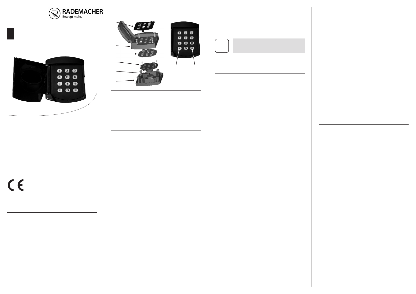
1. Gesamtansicht
4. Programmierung
4.4 Anmeldung am RolloPort Garagentorantrieb
Codierschaltgerät mit Funk
DE
Gebrauchsanleitung
Art.-Nr.: 8000 00 02
Sendfrequenz: 433,9 MHz
Sendeleistung: max. 10 mW
VBD 583-3 (05.19)
7
. Vereinfachte EU-Konformitätserklärung
Hiermit erklärt die RADEMACHER Geräte-Elektronik GmbH, dass das
Codierschaltgerät mit Funk
vollständige Text der EU-Konformitätserklärung ist unter der
Der
folgenden Internetadresse verfügbar: www.rademacher.de/ce
RADEMACHER
Geräte-Elektronik GmbH
Buschkamp 7
46414 Rhede (Deutschland)
info@rademacher.de
www.rademacher.de
Service:
Hotline 01807 933-171*
Telefax +49 2872 933-253
service@rademacher.de
(Art.-Nr. 8000 00 02) der Richtlinie
2
014/53/EU (Funkanlagenrichtlinie)
entspricht.
* 30 Sekunden kostenlos, danach
14 ct/Minute aus dem dt. Festnetz
bzw. max. 42 ct/ Minute aus dem
dt. Mobilfunknetz.
Technische Änderungen, Druckfehler und Irrtümer vorbehalten.
1
2
3
4
5
6
1. Tastenfeld
2. Gehäuseoberteil
3. Tastenfolie
4. Steuerungsplatine
5. Batterie
6. Gehäuseunterteil
7. [ * ]-Taste
8. [ # ]-Taste
2. Montage
1. Entfernen Sie das Tastenfeld mit einem Schraubendreher.
2. Schrauben Sie die Schrauben ab und entfernen Sie das
Gehäuseoberteil und die Tastenfolie.
3. Halten Sie das Gehäuseunterteil an die gewählte Montagestelle an der Mauer. Markieren Sie die Bohrlöcher mit
einem Bleistift. Bohren Sie 3 mm Löcher in Holzuntergrund
und 5 mm-Löcher in Mauerwerk.
4. Montieren Sie das Gehäuseunterteil an die Mauer. Setzen
Sie die Tastenfolie und das Gehäuseoberteil wieder
auf. Verschrauben Sie das Oberteil wieder fest mit dem
Gehäuseunterteil. Um Risse im Kunststoffgehäuse zu
vermeiden, ziehen Sie die Schrauben nicht zu stark an.
5. Bringen Sie das Tastenfeld wieder am Gehäuseoberteil an.
3. Batteriewechsel
Batterietyp: 2 × 3 V Batterie, Maxell CR2032
Die Leistung der zweiteiligen 3 V-Batterie sollte mindestens 1 Jahr
anhalten. Solange die Leistung ausreicht, leuchtet die Tastatur auf
und aktiviert den Antrieb nach Eingabe des Codes und Drücken der
[ # ]-Taste oder [ * ]-Taste. Ersetzen Sie die Batterie, wenn das Licht
schwächer wird.
1. Wiederholen Sie Schritt 1 und 2 der Montage.
2. Entfernen Sie die Schrauben auf der Steuerungsplatine
und nehmen Sie sie aus dem Gehäuseunterteil.
3. Ersetzen Sie die Batterien unter der Platine durch zwei
Abbildungen unverbindlich.
neue. Beachten Sie die Polarität der Batterien.
7 8
Mastercode und Öungscode im Auslieferungszustand
Das Codierschaltgerät hat einen „Mastercode“ und einen „Önungscode“. Im Auslieferungszustand sind beide Codes „0000“.
Zum Schutz vor unbefugtem Zugri sollten Sie
beide Codes unbedingt ändern.
i
◆ Ändern Sie zuerst den Mastercode, bevor Sie den
Önungscode ändern.
4.1 Zuerst den Mastercode ändern
1. Drücken Sie die [ # ]- und [ * ]-Taste gleichzeitig
5 Sekunden lang.
2. Lassen Sie beide Tasten los, sobald die LEDs rot blinken.
3. Drücken Sie noch einmal die [ # ]- und [ * ]-Taste gleichzeitig
5 Sekunden lang, bis die LEDs grün blinken.
4. Geben Sie den aktuellen Mastercode ein (z.B. 0000) und
drücken Sie die [ # ]-Taste.
Die LEDs blinken schneller.
5. Geben Sie nun einen neuen 4-stelligen Mastercode ein
und drücken Sie zur Bestätigung die [ # ]-Taste.
Die LEDs leuchten für ca. 2 Sekunden rot.
4.2 Den Önungscode ändern
1. Drücken Sie die [ # ]- und [ * ]-Taste gleichzeitig
5 Sekunden lang.
2. Lassen Sie beide Tasten los, sobald die LEDs rot blinken.
3. Geben Sie den aktuellen Önungscode (z.B. 0000) ein
und drücken Sie die [ # ]-Taste.
Die LEDs blinken schneller.
4. Geben Sie nun einen beliebigen Önungscode ein und
drücken Sie zur Bestätigung die [ # ]-Taste.
Der Önungscode kann bis zu 8 Stellen haben.
Die LEDs leuchten für ca. 2 Sekunden rot.
4.3 Reset
Sollten Sie den Önungscode vergessen haben, können Sie durch
folgende Schritte erreichen, dass der Mastercode als Önungscode
verwendet werden kann.
1. Önen Sie das Gehäuse, wie im Kapitel 2. beschrieben.
2. Drücken Sie die [#]- und [*]-Taste gleichzeitig 5 Sekunden
lang und lassen Sie beide Tasten los, sobald die LEDs rot
blinken.
3. Drücken und halten Sie anschließend die SW1-Taste auf
der Rückseite der Elektronik solange, bis die LEDs aufhören
zu blinken.
1. Bringen Sie den RolloPort in den Anmeldemodus.
Drücken Sie dazu die [ S ]-Taste am RolloPort für ca. 1 Sekunde.
2. Geben Sie nun innerhalb von 10 Sekunden zweimal den
Önungscode ein und betätigen Sie jeweils die [ # ]- oder
[ * ]-Taste, je nachdem mit welcher Taste Sie den Antrieb
ansteuern möchten.
3. Der Antrieb quittiert eine gültige Anmeldung durch
einen kurzen Piepton.
5. Bedienung
1. Geben Sie Ihren Önungscode ein und drücken Sie die
[ # ]- oder die [ * ]-Taste.-
2. Das Tor setzt sich nun in Bewegung.
6. Garantiebedingungen
RADEMACHER Geräte-Elektronik GmbH gibt eine 24-monatige Garantie
für Neugeräte, die entsprechend der Einbauanleitung montiert wurden.
Von der Garantie abgedeckt sind alle Konstruktionsfehler, Materialfehler
und Fabrikationsfehler. Ihre gesetzlichen Gewährleistungsansprüche
bleiben von dieser Garantie unberührt.
Ausgenommen von der Garantie sind:
◆ Fehlerhafter Einbau oder Installation
◆ Nichtbeachtung der Einbau- und Bedienungsanleitung
◆ Unsachgemäße Bedienung oder Beanspruchung
◆ Äußere Einwirkungen wie Stöße, Schläge oder Witterung
◆ Reparaturen und Abänderungen von dritten, nicht autorisierten
Stellen
◆ Verwendung ungeeigneter Zubehörteile
◆ Schäden durch unzulässige Überspannungen ( z. B. Blitzeinschlag )
◆ Funktionsstörungen durch Funkfrequenzüberlagerungen und
sonstige Funkstörungen
Voraussetzung für die Garantie ist, dass das Neugerät bei einem unserer
zugelassenen Fachhändler erworben wurde. Dies ist durch Vorlage einer
Rechnungskopie nachzuweisen.
Innerhalb der Garantiezeit auftretende Mängel beseitigt RADEMACHER
kostenlos entweder durch Reparatur oder durch Ersatz der betreenden
Teile oder durch Lieferung eines gleichwertigen oder neuen Ersatzgerätes. Durch Ersatzlieferung oder Reparatur aus Garantiegründen tritt
keine generelle Verlängerung der ursprünglichen Garantiezeit ein.
Page 2
1. General view
4. Programming
4.4 Registering on the RolloPort garage gate drive
Radio code switch
EN
Instruction manual
Item no: 8000 00 02
Transmission frequency: 433.9 MHz
Transmission power: max. 10 mW
VBD 583-3 (05.19)
Simplified EU Declaration of Conformity
7.
RADEMACHER Geräte-Elektronik GmbH hereby declares that the
Radio code switch (item no. 8000 00 02) complies with the
2014/53/EU (Radio Equipment Directive).
The full text of the declaration of conformity is available at the
following website: www.rademacher.de/ce
RADEMACHER
Geräte-Elektronik GmbH
Buschkamp 7
46414 Rhede (Germany)
info@rademacher.de
www.rademacher.de
Service:
Hotline 01807 933-171*
Fax +49 2872 933-253
service@rademacher.de
* 30 seconds free of charge, subse-
quently 14 cents / minute from German xed line networks and max.
42 cents / minute from German
mobile networks.
1
2
3
4
5
6
1. Button panel
2. Upper housing
3. Button sheet
4. Control board
5. Battery
6. Base housing
7. [ * ]-button
8. [ # ]-button
7 8
2. Installation
1. Remove the button panel with a screw driver.
2. Screw out the screws and remove the upper housing and
the button sheet.
3. Put the base housing against the selected location on the
wall and make marks on the wall though the installation
holes with a pencil. Drill holes of 3 mm for wood or 5 mm
for masonry.
4. Install the base housing to the wall. Reinstall the button
sheet and the upper housing, and screw it securely to the
base housing. To avoid cracking the plastic housing, do
not over tighten.
5. Reinstall the button panel to the upper housing.
3. Replacing battery
Type: 2 × 3 V battery, Maxell CR2032
The power of the dual 3 V battery should last at least 1 year. As long
as there is power, the keypad will light up and activate the drive after
entering the code and pressing the [ # ] button or [ * ] button. Replace
the battery if the light is weaker.
1. Repeat Steps 1. and 2. of the installation procedure.
2. Remove the screws on the control board and take it out of
the base housing.
3. Replace the batteries behind the control board with 2
new ones. Please take notice to the polarity.
Subject to technical modications, misprints and errors excepted.
Illustrations not binding.
Master code and opening code in the original supplied condition
The code switch device has a "master code" and an "opening code". In
the original supplied condition, both codes are "0000".
To provide protection against unauthorised access,
it is imperative that both codes are changed.
i
◆ First, change the master code before changing the
opening code.
4.1 First change the master code
1. Simultaneously press and hold the [ # ] and [ * ] buttons
for 5 seconds.
2. Release both buttons as soon as the LEDs ash red.
3. Simultaneously press and hold the [ # ] and [ * ] buttons
again for 5 seconds until the LEDs ash green.
4. Enter the current master code (e.g. 0000) and press the
[#] button.
The LEDs ash more rapidly.
5. Now, enter a new 4 digit master code and press the
[#] button to conrm.
The LEDs will light up red for approx. 2 seconds.
4.2 Change the opening code
1. Simultaneously press and hold the [ # ] and [ * ] keys for
5 seconds.
2. Release both buttons as soon as the LEDs ash red.
3. Enter the current opening code (e.g. 0000) and press the
[#] button.
The LEDs ash more rapidly.
4. Now, enter a new random opening code and press the
[#] button to conrm.
The opening code may consist of up to 8 digits.
The LEDs will light up red for approx. 2 seconds.
4.3 Reset
Should you have forgotten the opening code, you can use the master
code as the opening code by complying with the following steps.
1. Open the housing as described in chapter 2.
2. Simultaneously press and hold the [#] and [*] buttons for
5 seconds and release both buttons as soon as the LEDs
ash red.
3. Subsequently, press and hold the SW1 button on the reverse
side of the electronic device until the LEDs stop ashing.
1. Switch the RolloPort to the registering mode.
To do this, press and hold the [ S ] button on the RolloPort for
approx. 1 second.
2. Now, within 10 seconds, enter the opening code twice and
conrm this each time by pressing the [#] or [*] buttons,
depending with which button you would like to control
the drive.
3. The drive will conrm the registration as valid by beeping
briey.
5. Operating
1. Enter your opening code and then press button [ # ] or
button [ * ].
2. The garage door will now move.
6. Warranty Conditions
RADEMACHER Geräte-Elektronik GmbH provides a 24-month warranty for new systems that have been installed in compliance with the
installation instructions. All construction faults, material defects and
manufacturing defects shall be covered by the warranty. Your statutory
warranty claims shall remain unaected by this warranty.
The following shall not be covered by the warranty:
◆ Incorrect tting or installation
◆ Non-observance of the installation and operating instructions
◆ Improper operation or wear and tear
◆ External inuences, such as impacts, knocks or weathering
◆ Repairs and modications by third parties, unauthorised persons
◆ Use of unsuitable accessories
◆ Damage caused by unacceptable excess voltage (e.g. stroke of
lightning)
◆ Operational malfunctions caused by radio frequency overlapping
and other such radio interference
A prerequisite for the warrant is that the new device must have been
purchased from one of our approved specialist retailers. Proof of this
must be provided by presenting a copy of the bill.
RADEMACHER shall remedy any defects, which occur within the warranty
period free of charge either by repair or by replacement of the aected
parts or by supplying a new replacement unit or one to the same value.
There is no general extension of the original warranty period by delivery
of a replacement or by repair as per the terms of the warranty.
 Loading...