

Page 1

Tenor DX
®
VoIP MultiPath/Gateway
Switch
e
P
u
G
u
c
o
d
r
N
4
P
/
t
-
1
9
0
-
0
0
4
8
0
-
0
0
i
d
Tenor and Quintum are registered trademarks. PacketSaver, Quintum Technologies, Inc., Risk Free VoP,
VoIP Made Easy, TASQ, SelectNet, and SelectNet Technology are trad emarks of Quintum Technologies,
Inc.
Page 2

Table of Contents
About this Guide
What’s included? . . . . . . . . . . . . . . . . . . . . . . . . . . . . . . . . . . . . . . . . . . . . . . . . . . . . . . . . . 1-2
Typographical Conventions . . . . . . . . . . . . . . . . . . . . . . . . . . . . . . . . . . . . . . . . . . . . . . . . . 1-3
Product Guide Conventions. . . . . . . . . . . . . . . . . . . . . . . . . . . . . . . . . . . . . . . . . . . . . 1-3
Finding Help. . . . . . . . . . . . . . . . . . . . . . . . . . . . . . . . . . . . . . . . . . . . . . . . . . . . . . . . . . . . . 1-4
Chapter 1: Overview
What is the Tenor DX? . . . . . . . . . . . . . . . . . . . . . . . . . . . . . . . . . . . . . . . . . . . . . . . . . . . . 1-2
Features. . . . . . . . . . . . . . . . . . . . . . . . . . . . . . . . . . . . . . . . . . . . . . . . . . . . . . . . . . . . . . . . 1-4
Unique Design . . . . . . . . . . . . . . . . . . . . . . . . . . . . . . . . . . . . . . . . . . . . . . . . . . . . . . . 1-4
State-of-the-Art GUI Configuration and Network Management . . . . . . . . . . . . . . . . . . 1-4
SelectNet™ Technology Safety Net . . . . . . . . . . . . . . . . . . . . . . . . . . . . . . . . . . . . . . 1-4
PacketSaver™ reduces bandwidth consumption . . . . . . . . . . . . . . . . . . . . . . . . . . . . 1-5
Easy Connect to Console . . . . . . . . . . . . . . . . . . . . . . . . . . . . . . . . . . . . . . . . . . . . . . 1-5
Powerful System Monitoring . . . . . . . . . . . . . . . . . . . . . . . . . . . . . . . . . . . . . . . . . . . . 1-5
Capabilities . . . . . . . . . . . . . . . . . . . . . . . . . . . . . . . . . . . . . . . . . . . . . . . . . . . . . . . . . . . . . 1-6
Virtual Tie Line. . . . . . . . . . . . . . . . . . . . . . . . . . . . . . . . . . . . . . . . . . . . . . . . . . . . . . . 1-6
SNMP Support. . . . . . . . . . . . . . . . . . . . . . . . . . . . . . . . . . . . . . . . . . . . . . . . . . . . . . . 1-6
Call Detail Recording. . . . . . . . . . . . . . . . . . . . . . . . . . . . . . . . . . . . . . . . . . . . . . . . . . 1-6
IVR/RADIUS Support . . . . . . . . . . . . . . . . . . . . . . . . . . . . . . . . . . . . . . . . . . . . . . . . . 1-6
NATAccess™. . . . . . . . . . . . . . . . . . . . . . . . . . . . . . . . . . . . . . . . . . . . . . . . . . . . . . . . 1-7
Call Routing/Management Options . . . . . . . . . . . . . . . . . . . . . . . . . . . . . . . . . . . . . . . . . . . 1-8
Routing Table Options . . . . . . . . . . . . . . . . . . . . . . . . . . . . . . . . . . . . . . . . . . . . . . . . . 1-10
Call Management Features . . . . . . . . . . . . . . . . . . . . . . . . . . . . . . . . . . . . . . . . . . . . . . . . . 1-11
H.323 Gatekeeper Services. . . . . . . . . . . . . . . . . . . . . . . . . . . . . . . . . . . . . . . . . . . . . . . . . 1-12
Gatekeeper . . . . . . . . . . . . . . . . . . . . . . . . . . . . . . . . . . . . . . . . . . . . . . . . . . . . . . . . . 1-12
Zone Management. . . . . . . . . . . . . . . . . . . . . . . . . . . . . . . . . . . . . . . . . . . . . . . . . . . . 1-12
Call Registration. . . . . . . . . . . . . . . . . . . . . . . . . . . . . . . . . . . . . . . . . . . . . . . . . . . . . . 1-12
Border Element . . . . . . . . . . . . . . . . . . . . . . . . . . . . . . . . . . . . . . . . . . . . . . . . . . . . . . 1-12
Call Services . . . . . . . . . . . . . . . . . . . . . . . . . . . . . . . . . . . . . . . . . . . . . . . . . . . . . . . . 1-13
SIP User Agent . . . . . . . . . . . . . . . . . . . . . . . . . . . . . . . . . . . . . . . . . . . . . . . . . . . . . . . . . . 1-15
Chapter 2: Hardware Components
Hardware Description . . . . . . . . . . . . . . . . . . . . . . . . . . . . . . . . . . . . . . . . . . . . . . . . . . . . . 2-2
Front Panel Connections and Reset Options. . . . . . . . . . . . . . . . . . . . . . . . . . . . . . . . 2-2
Front Panel LEDs. . . . . . . . . . . . . . . . . . . . . . . . . . . . . . . . . . . . . . . . . . . . . . . . . . . . . 2-5
P/N 480-0049-00-10 TOC-1
Page 3

Back Panel. . . . . . . . . . . . . . . . . . . . . . . . . . . . . . . . . . . . . . . . . . . . . . . . . . . . . . . . . . 2-6
Cables . . . . . . . . . . . . . . . . . . . . . . . . . . . . . . . . . . . . . . . . . . . . . . . . . . . . . . . . . . . . . . . . . 2-7
RJ-45 Cables . . . . . . . . . . . . . . . . . . . . . . . . . . . . . . . . . . . . . . . . . . . . . . . . . . . . . . . . 2-7
DB-9 Serial RS-232 Cable. . . . . . . . . . . . . . . . . . . . . . . . . . . . . . . . . . . . . . . . . . . . . . 2-11
Chapter 3: Installation
Installation . . . . . . . . . . . . . . . . . . . . . . . . . . . . . . . . . . . . . . . . . . . . . . . . . . . . . . . . . . . . . . 3-2
Pre-Installation Guidelines. . . . . . . . . . . . . . . . . . . . . . . . . . . . . . . . . . . . . . . . . . . . . . 3-2
Inspect Package Contents. . . . . . . . . . . . . . . . . . . . . . . . . . . . . . . . . . . . . . . . . . . . . . 3-2
Rack Install . . . . . . . . . . . . . . . . . . . . . . . . . . . . . . . . . . . . . . . . . . . . . . . . . . . . . . . . . 3-3
Connection. . . . . . . . . . . . . . . . . . . . . . . . . . . . . . . . . . . . . . . . . . . . . . . . . . . . . . . . . . . . . . 3-6
Connect to Line Interface - PBX . . . . . . . . . . . . . . . . . . . . . . . . . . . . . . . . . . . . . . . . . 3-6
Connect to Trunk Interface - PSTN . . . . . . . . . . . . . . . . . . . . . . . . . . . . . . . . . . . . . . . 3-7
Connect to Ethernet LAN. . . . . . . . . . . . . . . . . . . . . . . . . . . . . . . . . . . . . . . . . . . . . . . 3-8
Connect to PC Console . . . . . . . . . . . . . . . . . . . . . . . . . . . . . . . . . . . . . . . . . . . . . . . . 3-9
Install Ground Safety Cable (if required) . . . . . . . . . . . . . . . . . . . . . . . . . . . . . . . . . . . . . . . 3-10
Power up the System. . . . . . . . . . . . . . . . . . . . . . . . . . . . . . . . . . . . . . . . . . . . . . . . . . . . . . 3-11
Assign IP Address . . . . . . . . . . . . . . . . . . . . . . . . . . . . . . . . . . . . . . . . . . . . . . . . . . . . . . . . 3-12
Change IP Address . . . . . . . . . . . . . . . . . . . . . . . . . . . . . . . . . . . . . . . . . . . . . . . . . . . 3-13
Load Software Upgrade. . . . . . . . . . . . . . . . . . . . . . . . . . . . . . . . . . . . . . . . . . . . . . . . . . . . 3-15
Chapter 4: Getting Started: Tenor Configuration Manager/Tenor Monitor
Overview . . . . . . . . . . . . . . . . . . . . . . . . . . . . . . . . . . . . . . . . . . . . . . . . . . . . . . . . . . . . . . . 4-2
Tenor Configuration Manager . . . . . . . . . . . . . . . . . . . . . . . . . . . . . . . . . . . . . . . . . . . . . . . 4-3
Getting Started with Configuration. . . . . . . . . . . . . . . . . . . . . . . . . . . . . . . . . . . . . . . . 4-3
Tenor Monitor . . . . . . . . . . . . . . . . . . . . . . . . . . . . . . . . . . . . . . . . . . . . . . . . . . . . . . . . . . . 4-4
Getting Started with Monitoring . . . . . . . . . . . . . . . . . . . . . . . . . . . . . . . . . . . . . . . . . . 4-4
Chapter 5: Getting Started: Command Line Interface (CLI)
What is the Command Line Interface? . . . . . . . . . . . . . . . . . . . . . . . . . . . . . . . . . . . . . . . . 5-2
Options. . . . . . . . . . . . . . . . . . . . . . . . . . . . . . . . . . . . . . . . . . . . . . . . . . . . . . . . . . . . . 5-2
Modes . . . . . . . . . . . . . . . . . . . . . . . . . . . . . . . . . . . . . . . . . . . . . . . . . . . . . . . . . . . . . 5-2
Navigation . . . . . . . . . . . . . . . . . . . . . . . . . . . . . . . . . . . . . . . . . . . . . . . . . . . . . . . . . . 5-2
User Login IDs . . . . . . . . . . . . . . . . . . . . . . . . . . . . . . . . . . . . . . . . . . . . . . . . . . . . . . . 5-3
Access CLI. . . . . . . . . . . . . . . . . . . . . . . . . . . . . . . . . . . . . . . . . . . . . . . . . . . . . . . . . . . . . . 5-3
Telnet Connection . . . . . . . . . . . . . . . . . . . . . . . . . . . . . . . . . . . . . . . . . . . . . . . . . . . . 5-3
Serial Port Connection. . . . . . . . . . . . . . . . . . . . . . . . . . . . . . . . . . . . . . . . . . . . . . . . . 5-4
Configuration via CLI . . . . . . . . . . . . . . . . . . . . . . . . . . . . . . . . . . . . . . . . . . . . . . . . . . . . . . 5-5
Chapter 6: Working with SNMP
What is SNMP? . . . . . . . . . . . . . . . . . . . . . . . . . . . . . . . . . . . . . . . . . . . . . . . . . . . . . . . . . . 6-2
How does Tenor DX utilize SNMP?. . . . . . . . . . . . . . . . . . . . . . . . . . . . . . . . . . . . . . . 6-2
P/N 480-0049-00-10 TOC-2
Page 4

Installation Requirements . . . . . . . . . . . . . . . . . . . . . . . . . . . . . . . . . . . . . . . . . . . . . . 6-2
Installation . . . . . . . . . . . . . . . . . . . . . . . . . . . . . . . . . . . . . . . . . . . . . . . . . . . . . . . . . . . . . . 6-3
Download and install SNMP-Related Files . . . . . . . . . . . . . . . . . . . . . . . . . . . . . . . . . 6-3
Configure Network Manager IP address . . . . . . . . . . . . . . . . . . . . . . . . . . . . . . . . . . . 6-5
Working with SNMP. . . . . . . . . . . . . . . . . . . . . . . . . . . . . . . . . . . . . . . . . . . . . . . . . . . . . . . 6-7
View traps . . . . . . . . . . . . . . . . . . . . . . . . . . . . . . . . . . . . . . . . . . . . . . . . . . . . . . . . . . 6-7
View Alarm Status via Tenor DX icon. . . . . . . . . . . . . . . . . . . . . . . . . . . . . . . . . . . . . 6-7
Launching Command Line Interface (CLI) from HP Openview . . . . . . . . . . . . . . . . . . 6-8
Set up Tenor DX status polling. . . . . . . . . . . . . . . . . . . . . . . . . . . . . . . . . . . . . . . . . . 6-8
Set up Debug Message Display window . . . . . . . . . . . . . . . . . . . . . . . . . . . . . . . . . . . 6-8
Chapter 7: Call Detail Recording
Overview . . . . . . . . . . . . . . . . . . . . . . . . . . . . . . . . . . . . . . . . . . . . . . . . . . . . . . . . . . . . . . . 7-2
What is a CDR?. . . . . . . . . . . . . . . . . . . . . . . . . . . . . . . . . . . . . . . . . . . . . . . . . . . . . . . . . . 7-3
Establish connection between Tenor DX and CDR Server . . . . . . . . . . . . . . . . . . . . . . . . . 7-4
Configure Tenor DX for connection to CDR Server. . . . . . . . . . . . . . . . . . . . . . . . . . . 7-5
Setup CDR Server and assign password . . . . . . . . . . . . . . . . . . . . . . . . . . . . . . . . . . 7-5
Change CDR Password. . . . . . . . . . . . . . . . . . . . . . . . . . . . . . . . . . . . . . . . . . . . . . . . 7-5
Tenor DX Establishes Connection with CDR Server. . . . . . . . . . . . . . . . . . . . . . . . . . . . . . 7-6
CDR Server Establishes Connection with Tenor DX. . . . . . . . . . . . . . . . . . . . . . . . . . . . . . 7-6
CDR Output . . . . . . . . . . . . . . . . . . . . . . . . . . . . . . . . . . . . . . . . . . . . . . . . . . . . . . . . . . . . . 7-7
Sample Record for Standard and Extended CDR Format 0, 1, 100, 101 . . . . . . . . . . 7-7
Sample Record for Extended Tenor DX CDR Format 3, 4, 103, 104:. . . . . . . . . . . . . 7-10
Chapter 8: System Alarms
Overview . . . . . . . . . . . . . . . . . . . . . . . . . . . . . . . . . . . . . . . . . . . . . . . . . . . . . . . . . . . . . . . 8-2
Monitor Alarms. . . . . . . . . . . . . . . . . . . . . . . . . . . . . . . . . . . . . . . . . . . . . . . . . . . . . . . . . . . 8-2
How to Read Alarms . . . . . . . . . . . . . . . . . . . . . . . . . . . . . . . . . . . . . . . . . . . . . . . . . . 8-2
Valid Alarms. . . . . . . . . . . . . . . . . . . . . . . . . . . . . . . . . . . . . . . . . . . . . . . . . . . . . . . . . 8-4
View Alarms. . . . . . . . . . . . . . . . . . . . . . . . . . . . . . . . . . . . . . . . . . . . . . . . . . . . . . . . . . . . . 8-7
Display all Alarms . . . . . . . . . . . . . . . . . . . . . . . . . . . . . . . . . . . . . . . . . . . . . . . . . . . . 8-7
Display Active Alarms . . . . . . . . . . . . . . . . . . . . . . . . . . . . . . . . . . . . . . . . . . . . . . . . . 8-7
Display Alarm History. . . . . . . . . . . . . . . . . . . . . . . . . . . . . . . . . . . . . . . . . . . . . . . . . . 8-8
Chapter 9: Diagnostics/Maintenance
Before you Begin. . . . . . . . . . . . . . . . . . . . . . . . . . . . . . . . . . . . . . . . . . . . . . . . . . . . . . . . . 9-2
Monitor LEDs. . . . . . . . . . . . . . . . . . . . . . . . . . . . . . . . . . . . . . . . . . . . . . . . . . . . . . . . . . . . 9-2
Diagnostics . . . . . . . . . . . . . . . . . . . . . . . . . . . . . . . . . . . . . . . . . . . . . . . . . . . . . . . . . . . . . 9-3
Common Symptoms/Problems . . . . . . . . . . . . . . . . . . . . . . . . . . . . . . . . . . . . . . . . . . 9-3
Verify Unit Provisioning . . . . . . . . . . . . . . . . . . . . . . . . . . . . . . . . . . . . . . . . . . . . . . . . 9-4
Ping Unit . . . . . . . . . . . . . . . . . . . . . . . . . . . . . . . . . . . . . . . . . . . . . . . . . . . . . . . . . . . 9-4
Monitoring . . . . . . . . . . . . . . . . . . . . . . . . . . . . . . . . . . . . . . . . . . . . . . . . . . . . . . . . . . . . . . 9-5
P/N 480-0049-00-10 TOC-3
Page 5

Alarms . . . . . . . . . . . . . . . . . . . . . . . . . . . . . . . . . . . . . . . . . . . . . . . . . . . . . . . . . . . . . 9-5
General Maintenance . . . . . . . . . . . . . . . . . . . . . . . . . . . . . . . . . . . . . . . . . . . . . . . . . . . . . 9-5
Restore Factory Defaults . . . . . . . . . . . . . . . . . . . . . . . . . . . . . . . . . . . . . . . . . . . . . . . 9-5
Reset System. . . . . . . . . . . . . . . . . . . . . . . . . . . . . . . . . . . . . . . . . . . . . . . . . . . . . . . . 9-5
Change Password . . . . . . . . . . . . . . . . . . . . . . . . . . . . . . . . . . . . . . . . . . . . . . . . . . . . 9-5
Change Unit Date and Time . . . . . . . . . . . . . . . . . . . . . . . . . . . . . . . . . . . . . . . . . . . . 9-6
If you need Additional Help . . . . . . . . . . . . . . . . . . . . . . . . . . . . . . . . . . . . . . . . . . . . . . . . . 9-7
Chapter 10: Using IVR
What is IVR? . . . . . . . . . . . . . . . . . . . . . . . . . . . . . . . . . . . . . . . . . . . . . . . . . . . . . . . . . . . . 10-2
IVR Call Types. . . . . . . . . . . . . . . . . . . . . . . . . . . . . . . . . . . . . . . . . . . . . . . . . . . . . . . 10-2
ANI Authentication . . . . . . . . . . . . . . . . . . . . . . . . . . . . . . . . . . . . . . . . . . . . . . . . . . . . 10-3
Multi-session . . . . . . . . . . . . . . . . . . . . . . . . . . . . . . . . . . . . . . . . . . . . . . . . . . . . . . . . 10-3
Typical IVR Network Connection/Process. . . . . . . . . . . . . . . . . . . . . . . . . . . . . . . . . . . . . . 10-4
Configure IVR - Quick Start . . . . . . . . . . . . . . . . . . . . . . . . . . . . . . . . . . . . . . . . . . . . . . . . . 10-6
Basic IVR Data (via Trunk Group) . . . . . . . . . . . . . . . . . . . . . . . . . . . . . . . . . . . . . . . . 10-6
RADIUS Server . . . . . . . . . . . . . . . . . . . . . . . . . . . . . . . . . . . . . . . . . . . . . . . . . . . . . . 10-6
Configure Voice Prompts. . . . . . . . . . . . . . . . . . . . . . . . . . . . . . . . . . . . . . . . . . . . . . . . . . . 10-7
Voice Prompt Requirements (English Requirements) . . . . . . . . . . . . . . . . . . . . . . . . . 10-7
Create Voice Prompt Files. . . . . . . . . . . . . . . . . . . . . . . . . . . . . . . . . . . . . . . . . . . . . . 10-10
Call Flow - Specifications. . . . . . . . . . . . . . . . . . . . . . . . . . . . . . . . . . . . . . . . . . . . . . . . . . . 10-11
Pre-paid Calling Card - Call Flow (with default language) . . . . . . . . . . . . . . . . . . . . . . 10-11
Post-paid Calling Card - Call Flow (with default language) . . . . . . . . . . . . . . . . . . . . . 10-13
Pre-paid and Post-paid Calling Card - Call Flow (with multiple language support) . . . 10-15
Pre-paid and Post-paid Calling Card - Call Flow (with Multi-Session Call support). . . 10-16
ANI Authentication Application Type 1 - Call Flow. . . . . . . . . . . . . . . . . . . . . . . . . . . . 10-18
ANI Authentication Application Type 2 - Call Flow. . . . . . . . . . . . . . . . . . . . . . . . . . . . 10-20
Call Flow - Message Attributes . . . . . . . . . . . . . . . . . . . . . . . . . . . . . . . . . . . . . . . . . . . . . . 10-22
Start Accounting Request Message Attributes . . . . . . . . . . . . . . . . . . . . . . . . . . . . . . 10-22
Stop Accounting Request Message Attributes. . . . . . . . . . . . . . . . . . . . . . . . . . . . . . . 10-23
Authentication Request Message Attributes . . . . . . . . . . . . . . . . . . . . . . . . . . . . . . . . 10-25
Authentication Response Message Attributes . . . . . . . . . . . . . . . . . . . . . . . . . . . . . . . 10-25
Authorization Request Message Attributes . . . . . . . . . . . . . . . . . . . . . . . . . . . . . . . . . 10-26
Authorization Response Message Attributes. . . . . . . . . . . . . . . . . . . . . . . . . . . . . . . . 10-27
Appendix A: Specifications/Approvals
INDEX
GLOSSARY
WARRANTY
Documentation Notice
P/N 480-0049-00-10 TOC-4
Page 6

About this Guide
P/N 480-0049-00-10 Preface-1
Page 7

About this Guide
What’s included?
This product guide is divided into chapters; each chapter describes a specific topic. The following chapters are
included:
• About this Guide: Describes what is included in the Product Guide, including typographical conventions.
• Chapter 1: Overview. Includes a general overview of the product, including a description of the Tenor
DX’s features and capabilities.
• Chapter 2: Hardware Components. Hardware description, including the front and rear panels, as well as
LEDs and required cables.
• Chapter 3: Installation. Describes how to install the Tenor DX unit, including how to connect, power up
and assign the IP address.
• Chapter 4: Getting Started: Tenor Configuration Manager/Tenor Monitor. This chapter tells you how to
use the Tenor Configuration Manager and Tenor Monitor to configure/monitor the unit.
• Chapter 5: Getting Star ted: Command Line Int erface (CLI). This chapter tells you how to access the CLI
and execute commands. A description of each CLI mode is also included.
• Chapter 6: Working with SNMP. This chapter describes the SNMP protocol and how to use it with the
Tenor DX.
• Chapter 7: Call Detail Recording. Describes the Call Detail Recording (CDR) feature, including how to
set up the CDR server and assign a password. In addition, instructions for reading CDR output are also
included.
• Chapter 8: System Alarms. Describes how to monitor and view alarms via Command Line Interface
(CLI). In addition, alarm definitions are also included.
• Chapter 9: Diagnostics/Maintenance. Describes how to troubleshoot and monitor the health of the system.
• Chapter 10: Using IVR. Describes the Interactive Voice Response (IVR) system for support of pre-paid
and post-paid calls.
• Appendix A: Specifications/Approvals: A list of Tenor DX specifications and approvals.
•Glossary
•Index
• Warranty
Preface-2 P/N 480-0049-00-10
Page 8

Typographical Conventions
Product Guide Conventions
Certain typographical conventions are used throughout this product guide. See below.
• All commands you enter via keystrokes appear in bold (e.g., Press Enter or Press Ctrl-I).
• All text commands you enter via Telnet session or command line typing appear in italics (e.g., type
active).
• There are three types of special text that are designed to reveal supplemental information: Note, Warning, and Caution. See below.
A NOTE provides additional, helpful information. This information may tell you how to do a certain
task or just be a reminder for how-to’s given in previous sections. (i.e., For a list of valid commands at
any time, type ?)
A WARNING provides information about how to avoid harming your VoIP equipment or other equipment (i.e., Do not stack more than 4 units together.)
About this Guide
A CAUTION provides information about how to avoid injury to yourself or to others (e.g., Do not install
the equipment during a lightning storm).
P/N 480-0049-00-10 Preface-3
Page 9

About this Guide
Finding Help
Refer to the Product Guide for help. The Table of Contents and Index tells you where to find information easily.
Extensive configuration help is available via the Tenor Configuraton Manager and Tenor Monitor online help
systems or the Command Line Interface online help system. See Chapter 4: Getting Started: Tenor Configu-
ration Manager/Tenor Monitor for more inf ormation.
Preface-4 P/N 480-0049-00-10
Page 10

Chapter 1: Overview
This chapter gives you a general overview of the Tenor DX including feature descriptions and capabilities. Specifically, the following topics are covered:
A description of Tenor DX
!
Features
!
! Capabilities
! Call Routing/Management Options
! H.323 Gatekeeper Services
P/N 480-0049-00-10 1-1
Page 11
Chapter 1: Overview
What is the Tenor DX?
The Tenor DX is a high-density VoIP (Voice over Internet Protocol) H.323/SIP switch that converts
voice, fax, and modem data on digital circuit switched trunks, and transmits it over the IP network.
The Tenor DX integrates a gateway, gatekeeper, border element, intelligent call routing, and supports H.323/SIP, and QoS all in one solution. The gateway converts circuit switched calls to VoIP
calls, the gatekeeper performs IP call routing functions, and the border element distributes the call
routing directories throughout the network.
With its MultiPath architecture, the Tenor DX can intelligently route calls between the PBX, the
PSTN, and the IP network to achieve the best combination of cost and quality. It can also route calls
over IP to reduce costs, and then transparently “hop off” to the PSTN, to reach off-net locations.
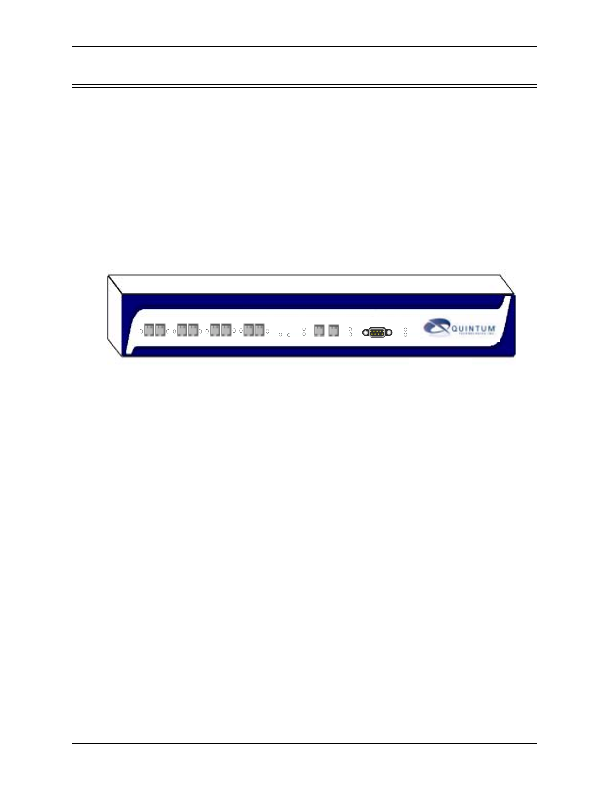
Figure 1-1
12 34 56 78
Tenor DX VoIP Switch
R
E
D
S
E
T
LAN 1 LAN 2
I
Line/Act
A
G
100
Line/Act
CONSOLE
100
POWER
ALERT
The Tenor DX is available in two configuration types:
• MultiPath Switch (intended for PBX and PSTN connectivity)
• Gateway (intended for VoIP and PSTN trunk port connectivity).
The MultiPath Switch is mainly intended for symmetrical multipath applications. The number of
VoIP channels is equal to half the number of PSTN channels.The MultiPath Switch configuration
enables connectivity between the customer equipment (i.e., PBX), PSTN and Vo IP Network. The
Gateway is mainly intended for trunking applications interfacing between the VoIP network and the
circuit switched network (PSTN). The number of VoIP channels equals the number of PSTN channels.
Whichever configuration you choose, the high performance unit provides two 10/100 BaseT connections and one RS-232 serial console port connection. The unit also incorporates an intelligent
call routing engine which regulates system resources and configuration while coordinating all voice
traffic activity in the unit.
The Tenor DX may be managed by the Tenor Configuration Manager and Tenor Monitor. Through
the Configuration Mana ger, you can configure all options, su ch as signaling d ata, trunk grou ps, dial
plans, and call routing numbers. An easy-to-use Java-based installation process enables you to an
install the manager and start configuring within minutes. Through the Tenor Monitor, you can mon-
itor the health of the system, including alarms, call detail records, etc. Both the Configuration Man-
ager and Tenor Monitor provide comprehensive on-line help systems that are available at your
fingertips.
1-2 P/N 480-0049-00-10
Page 12

Chapter 1: Overview
The unit’s simple plug and play embedded system architecture brings VoIP technology to your network without changing your existing telephony infrastructure. Your network stays as is, and the call
type is transparent to the user. This technology boasts superior voice quality without compromising
reliability.
The Tenor DX is available in the versions listed in Table 2-1.
Table 2-1 Tenor DX MultiPath Switch configurations
Tenor Digital DX
MultiPath
Configurations
DX2008 2 8 VoIP connections T1/E1
DX2016 2 16 VoIP connections T1/E1
DX2024 2 24 VoIP connections T1
DX2030 2 30 VoIP connections E1
DX4048 4 48 VoIP connections 2 x T1
DX4060 4 60 VoIP connections 2 x E1
DX6120 6 120 VoIP connections T1/E1
DX8120 8 120 VoIP connections T1/E1
Spans Available
(RJ-45 port for T1/E1
connection)
VoIP Channels Supported Usage
Table 2-2 Tenor DX Gateway configurations
Tenor Digital DX
Gateway
Configurations
Spans Available
(RJ-45 port for T1/E1
connection)
VoIP Channels Supported Usage
DX2048 2 48 VoIP connections 2 x T1
DX2060 2 60 VoIP connections 2 x E1
DX4096 4 96 VoIP connections 4 x T1
DX4120 4 120 VoIP connections 4 x E1
P/N 480-0049-00-10 1-3
Page 13

Chapter 1: Overview
Features
The Tenor DX’s specific features are explained below.
Unique Design
Tenor DX packs powerful VoIP features into one compact unit. The system’s embedded design
enables you to configure the unit directly without depending on another operating system; it can be
either placed on a table or mounted in a 19” rack.
With its MultiPath technology, the Tenor can be installed without upgrades to the existing voice or
data network. Tenor connects to the data network through a 10/100 Ethernet interface, and to the
enterprise and public voice network through multiple T1/E1 or PRI interfaces. In addition, with a
wide range of configurations available, it offers the flexibility for you to select a configuration that
best matches your needs.
State-of-the-Art GUI Configuration and Network Management
Once the unit is connected, the Tenor Configuration Manager makes configuring a Tenor DX easy.
Through the manager, you are able to set all configuration parameters, such as unit, signaling, and
call type features, as well as monitor the unit for alarms, and call information.
In addition, you can configure the unit via Command Line Interface (CLI). Through this simple telnet session, you can access all configuration options, including an online help system, built into the
CLI, which provides help for all features and functions. Just type help at any prompt, and data about
that field will be displayed.
SelectNet™ Technology Safety Net
Quality of service is virtually guaranteed. Tenor DX ’s built-in patented SelectNet
provides a “safety net,” which virtually guarantees that each call going VoIP will not only be routed
successfully, but will deliver high voice quality.
SelectNet monitors the IP network performance for VoIP calls. If the performance characteristics
become unacceptable—according to the delay , jitter, and packet loss specifications you configure—
the Tenor DX will switch the call to the PSTN automatically and transparently. The Tenor continuously monitors your data network for jitter, latency and packet loss, and transparently switches customer calls to the PSTN when required.
™ Technology
1-4 P/N 480-0049-00-10
Page 14
Chapter 1: Overview
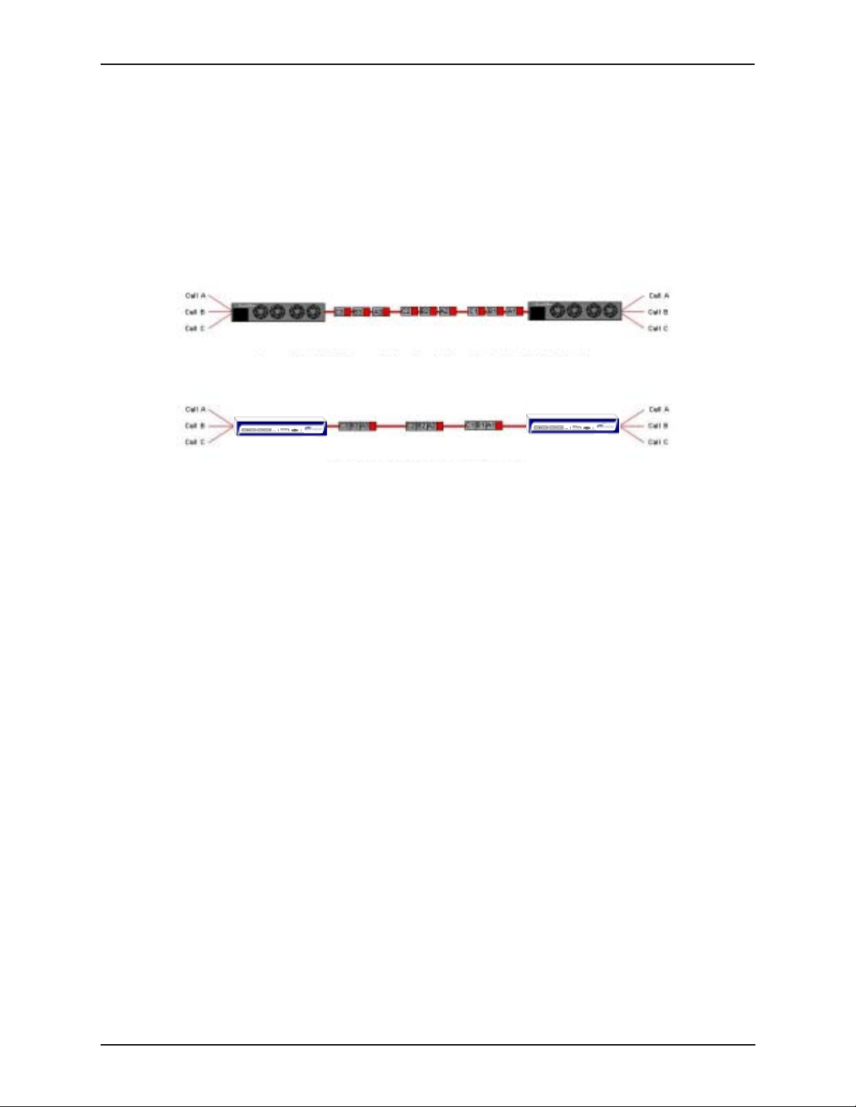
PacketSaver™ reduces bandwidth consumption
PacketSaver packet multiplexing technology reduces the amount of IP bandwidth required to support multiple calls flowing between two endpoints. PacketSaver minimizes bandwidth usage by
aggregating samples from multiple VoIP conversations and packing them into a larger IP packet
with a single IP header. The process removes the need to send a bulky IP header with individual
voice packets. As a result, it eliminates the transmission of redundant information.
.
Conventional V oIP Transmission Sends Many Redundant Packet Headers
R
E
D
12 34 56 78
R
E
D
CONSOLE
LAN 1 LAN 2
S
I
Line/Act
POWER
Line/Act
E
A
T
G
ALERT
100
100
12 34 56 78
CONSOLE
LAN 1 LAN 2
S
I
Line/Act
POWER
Line/Act
E
A
T
G
ALERT
100
100
Tenor using PacketSaver to Minimize Bandwidth Usage
Tenor
R
Tenor
R
Easy Connect to Console
Plugging a serial cable between the unit’s RS-232 port and your PC’s console port, will allow local
unit management. Through the console connection, you are able to assign an IP address. In addition,
if you are directly connected to the unit, you are able to configure the unit via Command Line Inter-
face (CLI).
Powerful System Monitoring
There are many different ways to monitor the health of the unit, including LEDs and alarms. LEDs
appear on the front of the unit. The LEDs light up according to operations and alarms the system is
experiencing.
Through the Tenor Monitor (see
tor
) and the Command Line Interface (CLI) (see Chapter 5: Getting Started: Command Line Inter-
Chapter 4: Getting Started: Tenor Configuration Manager/Tenor Moni-
face (CLI)), you can view a list of active system alarms, as well as view an alarm history . Each alarm
indicates the unit’s operational status.
P/N 480-0049-00-10 1-5
Page 15

Chapter 1: Overview
Capabilities
Virtual Tie Line
Tenor DX can emulate a tie trunk. It provides all of the functionality of a tie trunk, including the considerable cost savings, but eliminates the need for a PBX trunk to be configured, or marked as a tie
trunk. A traditional tie trunk is a PBX-configured direct connection between two PBXs in separate
locations. The tie trunk bypasses the PSTN network.
Your PBX does not need any additional configuration. Tenor DX treats all the trunks the same without compromising voice quality.
SNMP Support
The Tenor DX supports Simple Network Management Protocol (SNMP), the standard protocol used
to exchange network information between different types of networks. The Tenor DX unit acts as an
SNMP agent—using HP®
Manager. The Network Manager will then be able to perform certain functions, such as receiving
traps from the Tenor DX.
Openview™—to receive commands and issue responses to the Network
Call Detail Recording
Through the Call Detail Record (CDR) feature, the Tenor DX generates a call record at the completion of each call, typically for accounting purposes. A CDR is a string of data that contains call
information such as call date and time, call duration, calling party, and called party. Tenor DX may
store Call Detail Records locally or they can be sent to a CDR server within the network. The CDR
contains sufficient information to capture billing data, which can be used to create billing reports
using third party billing software.
IVR/RADIUS Support
Interactive Voice Response (IVR) is a feature of the Tenor DX that enables you to offer services,
such as Pre-paid calling cards and Post-paid accounts, to your customers.
The Tenor uses the RADIUS (Remote Authentication Dial-In User Service), for authenticating and
authorizing user access to the VoIP network, including ANI Authentication (Types 1 and 2). The
RADIUS is a standard protocol which provides a series of standardized message formats for transmitting and receiving dialed information, account data and authorization codes between the network
access gateway and the billing server.
1-6 P/N 480-0049-00-10
Page 16
Chapter 1: Overview
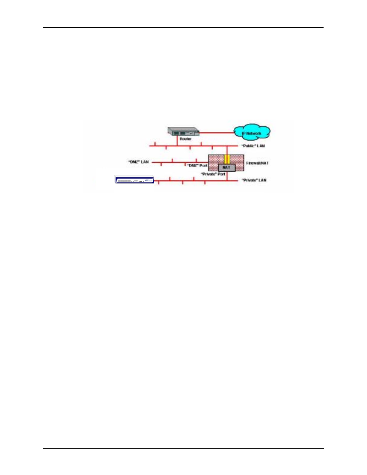
NATAccess™
NATAccess is an intelligent network address translation technology. It enables VoIP networks with
multiple H.323 endpoints to operate behind firewalls equipped with H.323 Network Address Translation (NAT); this provides maximum network security. NATAccess simplifies deployment by eliminating the need to place the Tenor on a public IP network. Using NATAccess provides easy, secure
expansion between multiple VoIP sites. In addition, NAT technology in the Tenor permits the use of
private subnets at the same time; in-house calls will never go over the public internet.
Figure 1-2 Tenor with NATAccess Deployment
R
E
D
12 34 56 78
CONSOLE
LAN 1 LAN 2
S
I
Line/Act
POWER
Line/Act
E
A
T
G
100
100
ALERT
P/N 480-0049-00-10 1-7
Page 17
Chapter 1: Overview
Call Routing/Management Options
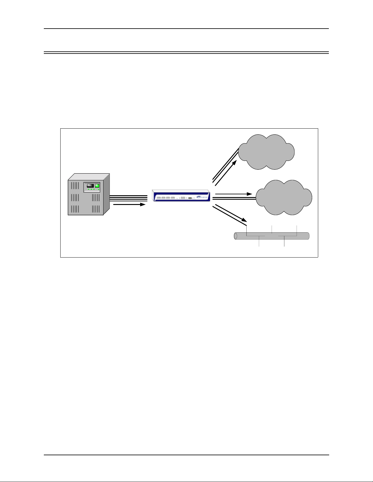
Call Routing
Line Circuit Originated Calls. Calls coming from a Line Circuit may be swi tched to either the data
network as a VoIP call or to a Trunk Circuit typically for connection to another circuit switched network such as the PSTN. The routing decision made by the Tenor is based upon your configuration
and the dialed number.
Figure 1-3 Line Circuit Call Routing
PSTN A
Circuit
Call
VOIP Call
PSTN B
Ethernet
PBX
Line
Circuits
Circuit
Call
12 34 56 78
Tenor DX
R
E
D
LAN 1 LAN 2
S
I
Line/Act
Line/Act
E
A
T
G
100
Tenor CMS
R
Trunk
Circuits
Trunk
CONSOLE
POWER
ALERT
100
Circuits
Ethernet
(IP Network)
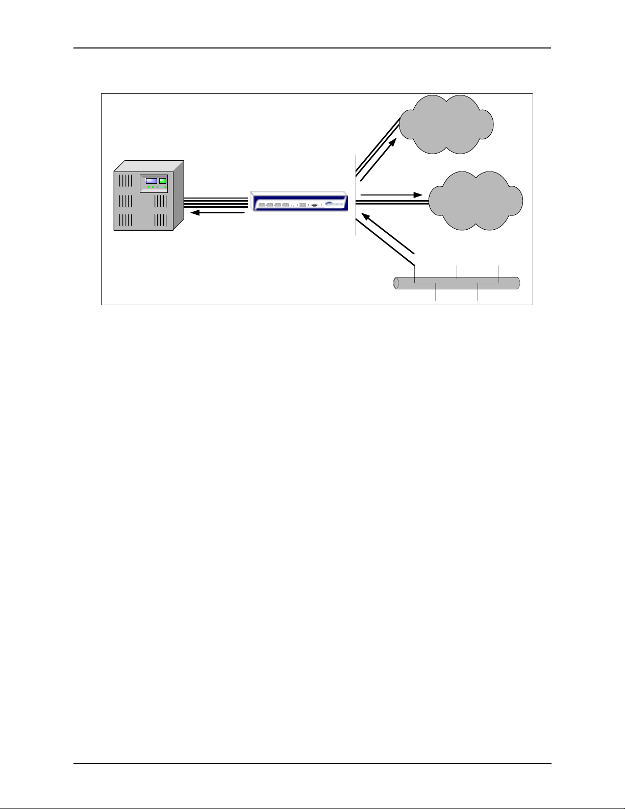
T runk Cir cuit Originated Calls. A call coming from a Trunk Circuit may be switched to either the
data network as a VoIP call, a Line Circuit, or trunk typically for conn ecti on to a termination device
on the user’s premises such as a PBX. The routing decision made by the Tenor DX is based upon
your configuration and the dialed number.
1-8 P/N 480-0049-00-10
Page 18
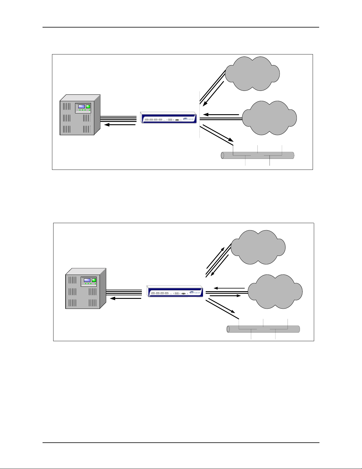
Figure 1-4 Trunk Circuit Call Routing
Chapter 1: Overview
PSTN A
Circuit
Call
VOIP Call
PSTN B
PBX
Line
Circuits
Circuit
Call
12 34 56 78
Tenor DX
R
E
D
LAN 1 LAN 2
S
I
Line/Act
Line/Act
E
A
T
G
100
Tenor CMS
R
Trunk
Circuits
Trunk
CONSOLE
POWER
ALERT
100
Circuits
Ethernet
(IP Network)
Ethernet
Intra-trunk Routing - “Hairpinning”. As a result of intra-trunk routing, incoming calls from a
particular Trunk Circuit are switched by Tenor DX to be routed back out the same trunk circuit routing group.
Figure 1-5 Intra-Trunk Routing
PSTN A
Circuit
Call
VOIP Call
PSTN B
PBX
Line
Circuits
Circuit
Call
12 34 56 78
Tenor DX
R
E
D
LAN 1 LAN 2
S
I
Line/Act
Line/Act
E
A
T
G
100
100
Tenor CMS
R
Trunk
Circuits
Trunk
CONSOLE
POWER
ALERT
Circuits
Ethernet
(IP Network)
Ethernet
Data Network Calls. Calls coming from the data network can be routed to the Line Circuit or T runk
Circuit spans. The Tenor will route calls based upon the dialed number. If the number is configured
as a local phone number, the call will be sent to a Line circuit for termination, otherwise the call is
considered a “Hop-Off call” and the Tenor sends it out through a Trunk Circuit span, typically connected to the PSTN.
P/N 480-0049-00-10 1-9
Page 19
Chapter 1: Overview
Figure 1-6 Data Network Call Routing
PSTN A
Circuit
Call
VOIP Call
PSTN B
Ethernet
PBX
Line
Circuits
Circuit
Call
12 34 56 78
Tenor DX
R
E
D
LAN 1 LAN 2
S
I
Line/Act
E
A
T
G
100
Tenor CMS
R
Trunk
Circuits
Trunk
Circuits
CONSOLE
Line/Act
POWER
ALERT
100
Ethernet
(IP Network)
Routing Table Options
There are four types of routing databases you can configure: Bypass Directory Numbers (BPN),
Hunt Local Directory Numbers (Hunt LDN), Hop-Off Directory Numbers (HDN) and Static Routes.
Bypass Directory Numbers. Bypass Directory Numbers (BDN) are telephone numbers that are
automatically routed directly from a line circuit to a trunk circuit (PSTN); they will not be routed
VoIP. Some examples of bypass numbers include toll-free calls, emergency calls (i.e., 911), or high
security calls.
Hunt Local Directory Numbers. A Hunt Local Directory Number (Hunt LDN) is a phone number
reachable through local Line Circuits.
Hop-Off Directory Number. A Hop-off PBX call travels over IP, and then “hops” off into the public network (PSTN) on the distant side to reduce or eliminate public toll charges (also known as
Leaky Area Map). A Hop-Off Directory Number is routed over the IP to another T enor location and
then out to the Trunk circuit, possibly to the PSTN as a local call.
Static Routes. Static Routes are used between networks and other H.323 devices that are not registered to the network through the Border Element (such as non-Quintum gateways). A static route
associates endpoints (as represented by their IP address) with Directory Number patterns.
1-10 P/N 480-0049-00-10
Page 20

Chapter 1: Overview
Call Management Features
Dynamic Call Routing. Tenor DX’s intelligent call routing capabilities are state-of-the-art. The unit
automatically detects and supports three call types: voice, fax, and modem.
Tenor DX will first identify the call origination site—trunk circuit, line circuit, or IP routing group
—and then route the call according to any parameters you have configured in the routing database.
Each call may be routed via circuit switched path between any two circuit groups, or compressed
and transported via VoIP when connecting to an IP routing group. Trunk circuits are those that typically connect to another circuit switched network such as the PSTN. Line circuits typically connect
to a termination device on the user premises, such as a PBX.
Trunk Group Support. The Tenor DX supports trunk groups, which are groups of T1 or E1 chan-
nels used to connect the Tenor to other carriers (such as local telephone company) or to PBX equipment used for circuit aggregation.
Public/Private Dial Plan Support.The Tenor DX supports public and private dial plans. A public
dial plan includes numbers which conform to the international dialing plan (E.164) of a country
code + city/area code + local number. For a public dial plan, you can define the numbering plan
structure for the Tenor DX to use for outgoing calls.
A private dial plan does not conform to a public dialing plan (i.e., 3 digit dialing plan); through the
Tenor DX you are able to configure the unique pattern/dialing plan structure, including number
length.
You are able to configure which dial plan to use for incoming and outgoing calls, including whether
other options such as hop-off calls, will use a public or private dial plan.
User Programmable Dial Plan Support. The User Programmable Dial Plan Support (UPDP)
enables the Tenor to identify a completely customizable set of digit sequences, such as Local,
National, International or Private Numbers.
PassThrough support for certain call types. Certain call types can be directly routed to a trunk
circuit, without going IP. There are several routing tables you can configure via the Configuration
Manager to adjust how the Tenor DX unit routes these types of “pass through” numbers. For example, you may want to configure 911 as a “bypass number”, which means that all 911 calls coming
into Tenor DX from the line circuit will be routed directly to a Trunk circuit presumably connected
to a PSTN. Bypass calls are never routed over IP.
Hop-off PBX Calls. Hop-off numbers are phone number patterns for calls to be routed out through
trunks. They are entered in a Hop-off Number Directory and associated with trunks where matching
calls should be sent.
Tenor DX supports those hop-off PBX calls where the destination Tenor DX is programmed to route
the call to the PSTN via Trunk Circuit. (A hop-off PBX call is a toll call which hops through a private network to reduce or eliminate the toll charge.) The destination Tenor DX unit is configured
with the phone numbers to be “supported” for this feature.
P/N 480-0049-00-10 1-11
Page 21

Chapter 1: Overview
H.323 Gatekeeper Services
The Tenor DX unit’s built-in H.323 gatekeeper performs IP call routing functions, such as call control and administrative services to another Tenor DX unit, or another H.323 endpoint. The gatekeeper’s functionality complies with the H.323 industry specifications for voice control and
management.
Gatekeeper
A Gatekeeper in an H.323 network provides call control services and other services to H.323 endpoints (i.e., gateways, terminals, and MCUs). The Tenor DX has a built-in H.323 gatekeeper which
complies to the H.323 industry specifications for voice control and management. The gatekeeper
performs call routing functions for calls entering and exiting a site.
The Gatekeeper performs IP call routing functions, such as Call Control Signaling and Call Authorization for Gateways, IP phones, and H.323 terminals. The Gatekeeper communicates with other
Gatekeepers through a Border Element. When using a group of Tenor DX units, you can assign one
unit as the Gatekeeper for the network. We recommend you configure each as its own gatekeeper.
Tenor DX supports gatekeeper to gatekeeper communication using the standard LRQ (Location
Request)/LCF (Location Confirm) messaging scheme.
Zone Management
A zone is a group of H.323 defined endpoints controlled by a Ga tekeeper. Endpoints can be gateways (i.e., Tenor DX), terminals, and/or multipoint conferencing units (MCUs). Endpoints establish
control channels with a gatekeeper for registration, admission, and security. Call routing information
about the endpoint is sent to the gatekeeper, including: IP address, unit type (gateway, terminal, or
MCU) and routing information (such as phone numbers, number patterns, etc.).
A collection of zones is an administrative domain. An administrative domain provides call routing
services for its zones through gatekeeper to gatekeeper messages or gatekeeper to border element
messages (see below for more information).
Call Registration
When registration from an H.323 endpoint is complete and a call is originated, the call request is
sent to the gatekeeper. The call request provides the Gatekeeper with the dialed number and requests
the routing information. The gatekeeper confirms the dialed number and supplies the endpoint with
the destination IP address. For example, a Tenor DX’s gatekeeper will act as the gatekeeper for that
zone and all of the other endpoints will register with it.
Border Element
The Tenor DX’s gatekeeper uses a border element to gain access to the routing database of the
administrative domain for the purpose of call completion or any other services that involve communications with other endpoints out of the administrative domain. The border element functionality is
built into the Tenor DX unit, along with the gateway and gatekeeper.
P/N 480-0049-00-10 1-12
Page 22
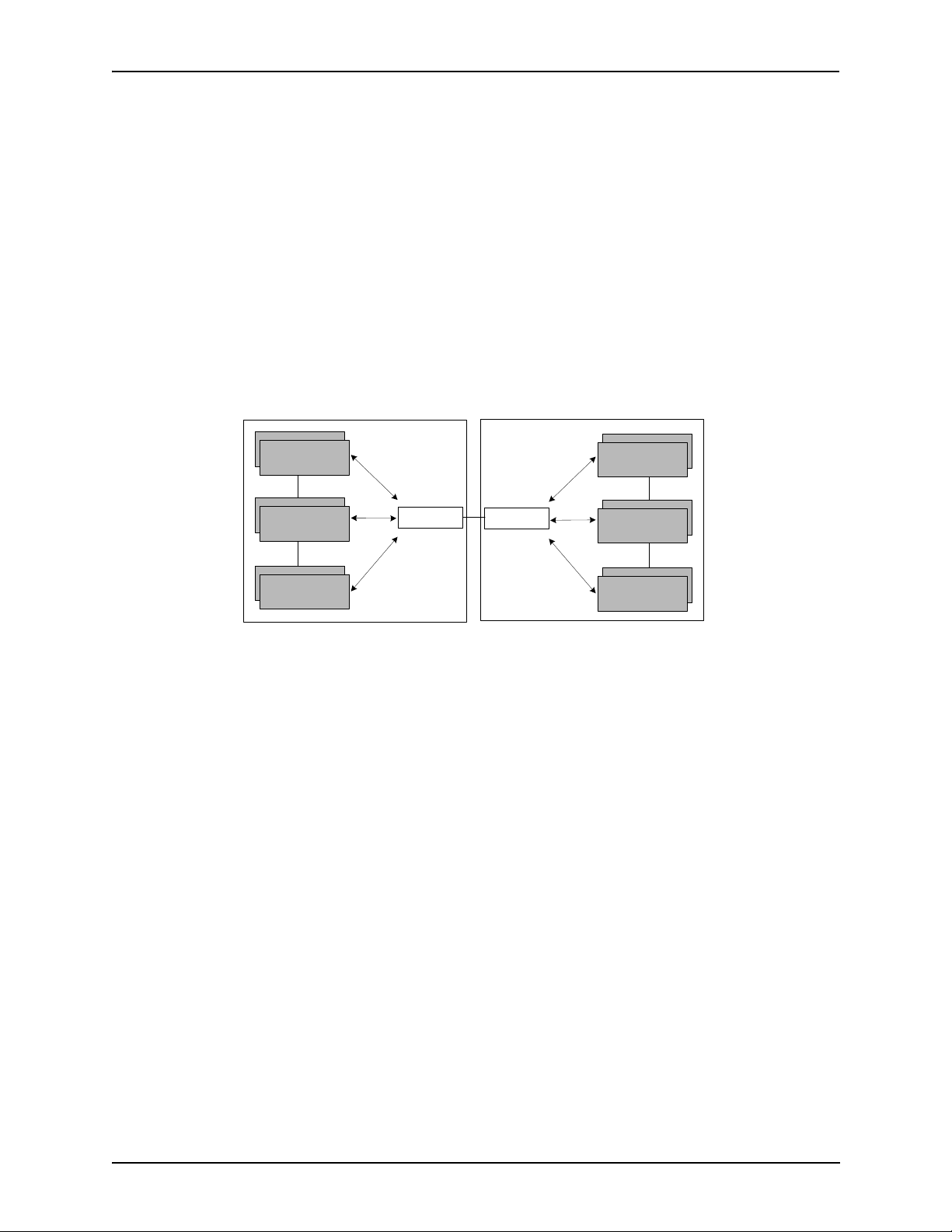
Chapter 1: Overview
The primary function of the border element is to collect, manage, and distribute call routing information. A gatekeeper will establish a service relationship with a border element; the gatekeeper provides its zones capabilities and the border element shares call routing capabilities of other zones in
the administrative domain. Through the border element, gatekeepers from multiple zones will be
able to communicate.
A border element also establishes relationships with other border elements to route between administrative domains. If a gatekeeper cannot resolve an address, it contacts the border element.
In addition, if you are using more than one T enor unit, you can configure one of the border elements
for that zone. The Tenor DX unit can use two border elements: primary and secondary. These work
together as one entity to provide redundancy and fault tolerance; there are no hierarchal differences.
Gatekeeper
Zone
Gatekeeper
Zone
Gatekeeper
Zone
Administrative Domain
Border Element
Border Element
Administrative Domain
Gatekeeper
Zone
Gatekeeper
Zone
Gatekeeper
Zone
Call Services
Gatekeepers provide services such as addressing, authorization and authentication of terminals and
gateways, bandwidth management, accounting, billing, and charging. Gatekeepers also provide callrouting services. Specifically, the Tenor DX Gatekeeper provides the functions which follow:
Address Translation. The gatekeeper translates telephone numbers into IP addresses and vice
versa. It performs Alias Address (phone number) to Transport Address (IP address) translation when
an endpoint requests service. The Gatekeeper uses a translation table to translate an Alias Address
(an address such as an H.323 identifier that a user may not understand) to a transport address. The
translation table is updated using Registration messages.
Autodiscovery. The gatekeeper is discovered in one of the following ways: An endpoint sends an IP
broadcast called a Gatekeeper Request message (GRQ) message (which includes that correct gatekeeper name) to discover a Gatekeeper OR the endpoint will discover a gatekeeper by its IP address.
Routing. The gatekeeper identifies the IP address of endpoints in its administrative domain. The
gatekeeper builds a routing database from information obtained from the border element and also
from gateways and H.323 endpoints.
P/N 480-0049-00-10 1-13
Page 23

Chapter 1: Overview
Admissions Control. All H.323 endpoints must register and request permission to enter the gatekeeper’s zone; the gatekeeper will confirm or deny access to the network. The gatekeeper authorizes
network access and protects the integrity of the network using Admissions Request (ARQ), Admissions Confirmation (ACF) and Admissions Reject (ARJ) messages.
P/N 480-0049-00-10 1-14
Page 24

Chapter 1: Overview
SIP User Agent
SIP (Session Initiation Protocol) is a signaling protocol used to establish a session on an IP network
for voice control and management; it is a request-response protocol that closely resembles Hypertext
Transfer Protocol (HTTP), which forms the basis of the World Wide Web. SIP re-uses many of the
constructs and concepts of Internet protocols such as HTTP and Simple Mail Transfer Protocol
(SMTP). The purpose of SIP is only to establish/change/terminate sessions. SIP is not concerned
with the content or details of the session.
SIP is Transport layer-independent, which means it can be used with any transport protocol: UDP,
TCP, ATM, etc. It is text-based, so it requires no encoding/decoding like H.323. And SIP supports
user mobility, using proxies and redirecting requests to your current location.
When configured for SIP the Tenor will act as a SIP User Agent (Endpoint) as defined in IETF
RFC3261. Multiple user agents allow for separate agents to be allocated to each SIP call. It will be
able to gateway calls to and from the IP network, and Customer Premise Equipment (CPE) such as
phones, PBX's, and FAX machines, or the Public Switched Telephone Network (PSTN). The Tenor
SIP User Agent will work in conjunction with an external SIP proxy or redirect server to route and
connect calls over SIP based networks.
There are three basic components of SIP:
1. User Agent (Endpoint)
• client element, initiates calls
• server element, answers calls
2. Network Server (Proxy Server or Redirect Server)
• name resolution
• user location
• redirect and forking
3. Registrar
• Stores registration information in a location service using a non-SIP protocol.
P/N 480-0049-00-10 1-15
Page 25

Chapter 2: Hardware Components
This chapter tells you what is contained in your hardware package. A description of each component is also
included.
Specifically, the following topics are covered:
! Hardware Description
! Cables
P/N 480-0049-00-10 2-1
Page 26
Chapter 2: Hardware Components
Hardware Description
The Tenor DX is a stackable/rack mountable device which provides PSTN and PBX connections (through T1/
E1/PRI lines), as well as connections to the Ethernet LAN and a PC. The unit provides eight RJ-45 ports in
which you can connect to a PBX or the PSTN.
The unit’s front panel includes connection jacks, LEDs, a reset button, and a diagnostics option; the back
panel includes a power cord connection site, an on/off switch, and a label.
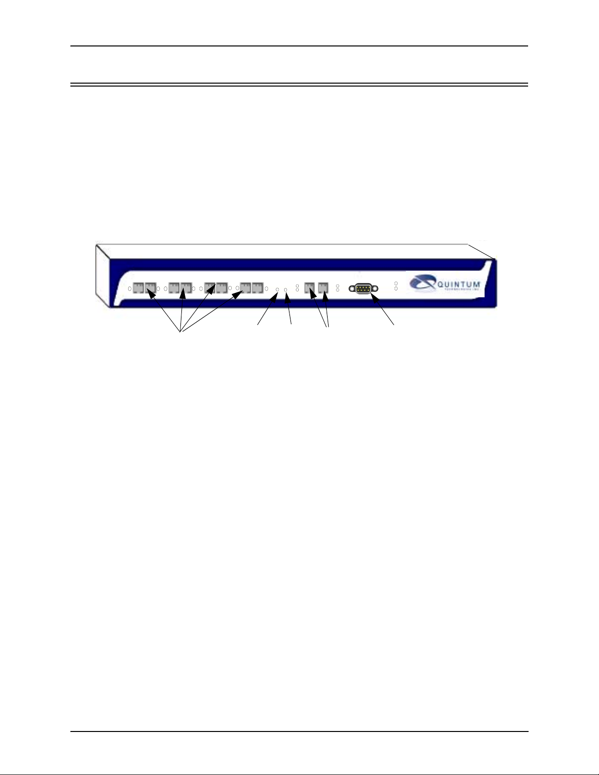
Front Panel Connections and Reset Options
Figure 2-1 Tenor DX Front Panel
R
D
1 2 34 56 7 8
E
LAN 1 LAN 2
I
S
A
E
Line/Act
G
T
100
Line/Act
CONSOLE
100
POWER
ALERT
Console Port
Port
Reset
Diag
LAN1/LAN2
• Ports 1-8. One RJ-45 jack for each port supports a connection to a line side (PBX) or other customer
equipment via upstream T1 or E1 lines, or to the trunk side (PSTN) via downstream T1 or E1 lines.
Each T1 line provides 24 channels. For each T1 interface, there are two types of signaling supported:
Channel Associated Signaling (CAS) and Common Channel Signaling (CCS). For T1 using CAS, channels 1-24 are available; for T1 using CCS, channels 1-23 are available.
Each E1 line provides 30B (Bearer) channels and 1D (Data) signaling channel. For each E1 interface,
there are two types of signaling supported: Channel Associated Signaling (CAS) and Common Channel
Signaling (CCS).
Adjacent port pairs (i.e., 1/2, 3/4, etc.) are configured by default to connect to each other (power off
bypass) when the unit is turned off, or when the unit is in Offline mode. This is the preferred method
when connecting one of the lines to a PBX, and its adjacent pair to the PSTN. However, if you have adjacent port pairs that are connected to smaller devices (i.e., both going to PSTN) in which you do not want
the two ports to be connected to each other in case of power off or offline, you should set the power off
bypass = 0. Each pair of ports (1/2, 3/4, 5/6 and 7/8) have their own online/offline and power off bypass
control. See the Tenor Configuration Manager online help or the Command Line Interface (CLI) guide
for specific configuration information.
• Reset. Enables you to reset the system.
• Diag. Enables you to perform software diagnostic procedures.
• LAN 1/LAN2. 10/100 Base-T Ethernet ports. LAN 1 port provides an RJ-45 jack for an individual con-
nection to a 10/100 Ethernet LAN switch or hub via RJ-45 cable; it is individually configured with a
unique IP and MAC address. LAN2 Ethernet port is reserved for future use.
2-2 P/N 480-0049-00-10
Page 27
Chapter 2: Hardware Components
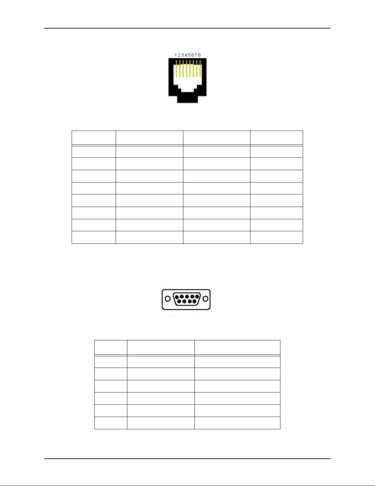
Figure 2-2 10/100 BASE-T Ethernet Port Pin Order
Table 2-1 Input/Output 10/100 Ethernet port
Pin # Signal Definition Color
1 TX + Transmit Data White w/orange
2 TX - Transmit Data Orange
3 RX + Receive Data White w/green
4 RSVD Reserved Blue
5 RSVD Reserved White w/blue
6 RX - Receive Data Green
7 RSVD Reserved White w/Brown
8 RSVD Reserved Brown
• Console port. This RS-232 connector is used for connection to a PC’s serial port via DB-9 serial cable at
38400 BPS 8N1, without flow control. The input/output signals are listed in Table 2-2.
Figure 2-3 DB-9 Female Connector Pin Order
5 4 3 2 1
9 8 7 6
Table 2-2 Serial RS232 DB-9 Connector Pinouts
Pin # Function Description
1 DTR Data Terminal Ready
2 TXD Transmit Data
3 RXD Receive Data
4 CD Carrier Detect
5 GND Signal Ground
6 N.C. No Connect
P/N 480-0049-00-10 2-3
Page 28

Chapter 2: Hardware Components
Pin # Function Description
7 N.C. No Connect
8 N.C. No Connect
9 N.C. No Connect
2-4 P/N 480-0049-00-10
Page 29

Chapter 2: Hardware Components
Front Panel LEDs
The LEDs display the health of the system. There are different types of LEDs: network, LAN, Alert and
Power. For LED definitions, see Table 2-3.
Figure 2-4 Front Panel LEDs
R
D
1 2 34 56 7 8
E
LAN 1 LAN 2
I
S
A
E
Line/Act
G
T
100
Line/Act
CONSOLE
100
POWER
ALERT
Network LEDs
LAN LEDs
Alert LED
Power LED
Table 2-3 Front Panel LEDs Definitions
LED Label LED Color Description
Red Receive Path Error Indication. Line
is not connected or other receive
Network
(PSTN) or
PBX
LAN1
LAN2 (LAN 2
is reserved for
future use)
1-8
errors.
Y ellow Receive Path Error Indication. Line
is not connected or other receive
errors.
Green Indicates B channels are busy.
Off The port is empty.
Link/ACT Green On: Link is good.
Flashing: Line is working properly
and activity is on the line.
Off: Link has failed.
100 Green On: Activity is being transmitted at
100 Mbps.
Off: Activity is being transmitted at
10 Mbps.
Power Power Green On: Indicates power is on.
Off: Power is off.
Alert Alert Amber Operational Status.
Off: Tenor DX is working prop-
erly.
On: One or more diagnostic tests
have failed.
P/N 480-0049-00-10 2-5
Page 30
Chapter 2: Hardware Components
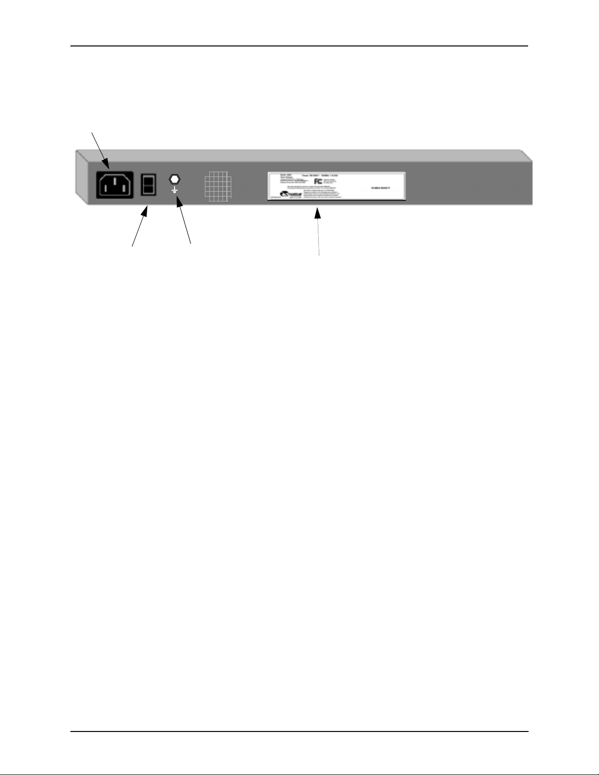
Back Panel
AC Receptacle
Power Switch
• AC Receptacle. Receptacle in which to plug in a power cord; the other end will plug into an AC outlet
for power.
• Power Switch. Switch to turn power on and off.
• Ground Screw . An earth ground screw provided to connect to earth ground using a Ground Safety Cable
(if your AC power plug only has two prongs and does not have a third, grounded prong ).
• Label. A label that displays UL, model, and power information.
Ground Screw
Label
2-6 P/N 480-0049-00-10
Page 31

Chapter 2: Hardware Components
Cables
The cables listed in Table 2-4 are required to connect a Tenor DX to various interfaces. Contact Quintum for
ordering information, if necessary.
NOTE: A crossover cable is required when connecting to a Line side (PBX) interface (when supplied by
Quintum, this is a red RJ-45 cable). A straight cable is required when connecting to the trunk side
(PSTN) interface (when supplied by Quintum, this is a green RJ-45 cable).
Table 2-4 Cables Supported
Cable Usage
RJ-45 to RJ-45 Crossover Cable (this cable is red
if provided by Quintum)
RJ-45 to RJ-45 Straight Through cable (this cable
is green if provided by Quintum)
T1/E1 connection Line Side Side (PBX) interface.
T1/E1 connection to Trunk Side (PSTN) inter-
face.
RJ-45 Ethernet cable (grey or white) Connection to Ethernet LAN 10/100.
DB-9 Serial RS-232 Connection to PC’s asynchronous console
port.
Detachable (IEC) AC Power Supply Cord Connection to AC power jack.
RJ-45 Cables
RJ-45 cable connector pinouts are given in this section to help you identify the proper connector to accommodate your specific networking requirements. The RJ-45 (ISO 8877) connector is the EIA/TIA standard for
Unshielded Twisted Pair (UTP) cable; the wiring color codes are UTP Standard Coloring. The pin order is
shown in Figure 2-5.
Figure 2-5 RJ-45 Pin Order
Side View
8
1
Top View
1
8
P/N 480-0049-00-10 2-7
Page 32

Chapter 2: Hardware Components
RJ-45 Ethernet Cable (10/100)
An RJ-45 (10/100BaseT) straight through shielded cable is used to connect Tenor DX to an Ethernet LAN.
Cable pinouts are listed in Table 2-5. Color specifications are applicable to the RJ-45 cable provided.
Figure 2-6 RJ-45 (10/100BT) Connector Pinouts
Pin # Connects to Pin #
1
2
3
4
5
6
7
8
1
2
3
4
5
6
7
8
Table 2-5 RJ-45 (10/100BT) Connector Pinouts
Pin # Signal Definition Color
1 TX + Transmit Data White w/orange
2 TX - Transmit Data Orange
3 RX + Receive Data White w/green
4 Unused Unused Blue
5 Unused Unused White w/blue
6 RX - Receive Data Green
7 Unused Unused White w/Brown
8 Unused Unused Brown
2-8 P/N 480-0049-00-10
Page 33

Chapter 2: Hardware Components
RJ-45 to RJ-45 Straight Cable (T1/E1/PRI WAN to Trunk Side)
An RJ-45 (T1/E1) straight cable is used to connect Tenor DX T1/E1 (1-8) port to the Trunk Side (PSTN).
Cable pinouts are provided below. If this cable is provided by Quintum, the color is green. The color specifications are applicable to the RJ-45 straight cable provided.
Figure 2-7 RJ-45 (T1/E1/PRI) Connector Pinouts
Pin # Connects to Pin #
1
2
3
4
5
6
7
8
1
2
3
4
5
6
7
8
Table 2-6 RJ-45 Connector Pinouts for T1/E1/PRI
Pin # Signal Definition Color
1 RX ring Receive Ring White w/orange
2 RX tip Receive Tip Orange
3 RSVD Reserved White w/green
4 TX ring Transmit Ring Blue
5 TX tip Transmit Tip White w/blue
6 N.C No Connect Green
7 N.C. No Connect White w/Brown
8 N.C. No Connect Brown
P/N 480-0049-00-10 2-9
Page 34

Chapter 2: Hardware Components
RJ-45 to RJ-45 Crossover Cable (T1/E1/PRI WAN to PBX)
An RJ-45 (T1/E1) crossover cable is used to connect Tenor DX T1/E1 (1-8) port to the Line Side (PBX).
Cable pinouts are provided below. If this cable is provided by Quintum, the color is red. The color specifications are applicable to the RJ-45 crossover cable provided.
Figure 2-8 RJ-45 Crossover Cable Pinouts
Connector 1 Connector 2
Pin # Connects to Pin #
1
2
3
4
5
6
7
8
1
2
3
4
5
6
7
8
Table 2-7 RJ-45 Connector Pinouts for T1/E1/PRI (1-8) port
Pin # Signal Definition Color for Connector 1 Color for Connector 2
1 RX ring Receive Ring White w/orange Blue
2 RX tip Receive Tip Orange White w/blue
3 RSVD Reserved 4 TX ring Transmit Ring Blue White w/orange
5 TX tip Transmit Tip White w/blue Orange
6 N.C No Connect - 7 N.C. No Connect - 8 N.C. No Connect - -
2-10 P/N 480-0049-00-10
Page 35

Chapter 2: Hardware Components
DB-9 Serial RS-232 Cable
The Serial RS-232 9-pin cable with a DB-9 male connector (with RS-232 interface) is used to connect the
Tenor DX to your PC’s asynchronous serial port. The pin order for DB-9 male and female connectors are
shown in Figure 2-9 and Figure 2-10.
Figure 2-9 DB-9 Male Connector Pin Order
1 2 3 4 5
6 7 8 9
Figure 2-10 DB-9 Female Connector Pin Order
5 4 3 2 1
9 8 7 6
Figure 2-11 DB-9 Connector Pinouts
Pin # Connec ts to Pin #
1
2
3
4
5
6
7
8
9
1
2
3
4
5
6
7
8
9
Table 2-8 DB-9 Connector Pinouts
Pin # Function Description Pin #
1 DTR Data Terminal Ready 1
2 TXD TransmitData 2
3 RXD Receive Data 3
4 CD Carrier Detect 4
5 GND Signal Ground 5
6 N.C. No Connect 6
7 N.C. No Connect 7
8 N.C. No Connect 8
9 N.C. No Connect 9
P/N 480-0049-00-10 2-11
Page 36

Chapter 3: Installation
This chapter gives you installation instructions, as well as how to position the Tenor DX successfully within
your network.
Specifically, the following topics are covered:
! Installation
! Connection
! Install Ground Safety Cable
! Power up the System
! Assign IP Address
P/N 480-0049-00-10 3-1
Page 37

Chapter 3: Installation
Installation
Before you begin the actual installation, review the pre-installation guidelines which follow and inspect the
package contents.
Pre-Installation Guidelines
• Always use an anti-static wrist strap when handling the unit.
• Do not open the unit cover. Inside parts have hazardous voltages and are extremely sensitive to static. If
the unit has been opened, your warranty is void.
• Do not connect equipment in wet conditions and keep away from dusty areas.
• The area must not exceed the temperature and humidity guidelines outlined in Appendix A: Technical
Specifications.
• Avoid exposing the chassis to excessive vibrations.
• Mechanical loading of rack should be considered so that the rack remains stable and unlikely to tip over.
Ensure no equipment is put on top of the chassis.
Inspect Package Contents
Before you install the hardware, ensure the following components are included in your shipment:
• Tenor Tenor DX and Mounting Hardware
• 1 AC Power Cable
• DB-9 RS-232 Serial Cable
• RJ-45 LAN Cable
• Correct quantity of RJ-45 cables associated with your custom configuration
• Product Guide in CD format
If a listed component is not included in your package, contact your customer service representative.
3-2 P/N 480-0049-00-10
Page 38

Chapter 3: Installation
Rack Install
Locate the Tenor DX unit within the same area as your PBX, Ethernet hub, switch, router, and/or PSTN patch
panel. The chassis is intended to be installed in a 19” rack.
Mounting brackets are attached to the chassis; the rack is not included with your system. Included with the
chassis are the screws and clip nuts listed below . The sizes should allow installation in most racks. If your rack
does not use the same size screws listed in the table, please consult the instructions you received with the rack.
Required Materials
• 19” rack (not included with system)
• #8 - 32 x 3/8 screws (qty: 2) (included with system)
• screws as required by your rack manufacturer
Install the chassis in a rack as follows:
1. Choose a position for the chassis within the rack.
WARNING: If the Tenor DX unit is the only equipment installed in the rack, ensure it is level with the rack
to avoid the rack from becoming unbalanced. Mount as low as possible to avoid a high center
of gravity.
2. Align the unit’s mounting brackets flush with the rack’s mounti ng hol es (see Figure 3-1 ) and follow the
vendor specific instructions for rack installation. The screws provided require a Phillips #2 screwdriver.
3. Ensure the chassis is secured firmly to the rack.
P/N 480-0049-00-10 3-3
Page 39

Chapter 3: Installation
Rack
Mounting
Holes
Figure 3-1 Rack Installation (Front View)
Tenor DX
Wall Mount
There are two mounting brackets available to mount the unit to the wall.
Pre-installation Guidelines
• Ensure the wall is level and stable.
• Do not attach the unit to a temporary wall.
• Ensure the wall mounting area is within cord distance of the power outlet.
Required Materials
• 2 wall mounting brackets (including 2 screws)
•Drill
• 3/16 drill bit
• Measuring tape or ruler
•Hammer
• Phillips head screwdriver
3-4 P/N 480-0049-00-10
Page 40

Chapter 3: Installation
Attach the unit to the wall as follows:
1. Determine the wall area to mount the unit. With chalk or a soft pencil, mark the install area according to
Figure 3-2.
NOTE: Ensure the unit is level.
Figure 3-2 Wall Mounting Dimensions
7 3/4” (19.9cm)
2. Position and attach one mounting bracket to the unit using a screw existing in the system and one screw
included with the package. See Figure 3-3.
3. Position and attach the other mounting bracket using a screw existing in the system and the remaining
screw in the package. See Figure 3-3.
3/16”
Figure 3-3 Wall Mount Installation
Mounting
Brackets
Attach each bracket to the
unit using 1 screw already installed
Unit front
in the unit (unscrew and re-insert)
and 1 screw already included
with the package.
Note: Ensure unit is level.
4. Mount the unit to the wall using the four remaining screws included with the system.
5. Ensure the unit is firmly mounted against the wall.
P/N 480-0049-00-10 3-5
Page 41

Chapter 3: Installation
Connection
Connect to Line Interface - PBX
Since there are many different PBX devices and connection methods, your individual PBX will determine the
connection method you use to connect to the unit. For example, your PBX may be connected using a patch
panel, punch down block, wire wrapped blocks, etc. If you are not sure about installation procedures, contact
the network administrator or review the documentation you received with the PBX.
Adjacent port pairs (i.e., 1/2, 3/4, etc.) are configured by default to connect to each other (power off bypass)
when the unit is turned off, or when the unit is in Offline mode. This is the preferred method when connecting
one of the lines to a PBX, and its adjacent pair to the PSTN. However, if you have adjacent port pairs that are
connected to smaller devices (i.e., both going to PSTN) in which you do not want the two ports to be connected to each other in case of power off or offline, you should set the power off bypass = 0. Each pair of ports
(1/2, 3/4, 5/6 and 7/8) have their own online/offline and power off bypass control. See the Tenor Configuration
Manager online help or the Command Line Interface (CLI) guide for specific configuration information.
You may use your PBX documentation, along with other PBX materials, to determine how to connect the
other end of the RJ-45 cable to your PBX. See Chapter 2: Hardware Components for the RJ-45 cable pinouts
you can use to acquire another cable or adapter that may be required to connect your specific PBX to the unit.
No changes are required to the PBX itself; you will need only the correct cable or adapter.
The instructions which follow tell you how to connect an RJ-45 cable (included in your package) between one
of the eight network ports on the Tenor DX and a PBX. See Chapter 2: Hardwar e Components for a list of RJ45 cable pinouts you can use to make a custom cable.
Figure 3-4 Connect to Line Interface
R
E
1 2 34 56 78
D
S
I
E
A
Line/Act
T
G
100
Insert ports 1-8
Connect to Line Interface as follows:
1. Plug one end of the crossover RJ-45 cable into one of the eight network ports on the front of the unit. (This
cable from Quintum would be the red RJ-45 crossover cable.) See Chapter 2: Hardware Components for
cable pinouts if you are making your own cable.
2. Connect the other end of the crossover RJ-45 cable into the appropriate port on the PBX. (If another cable
or adapter is required, see Chapter 2: Hardware Components for RJ-45 crossover pinout information.)
LAN 1 LAN 2
CONSOLE
Line/Act
POWER
ALERT
100
RJ-45 Crossover
PBX
NOTE: If you are connecting to an external CSU, ensure the Digital Interface is configured as short haul (or
DSX-1); otherwise, configure the Digital Interface to DS-1 to enable the built in CSU via Command Line Interface (CLI). See Chapter 4: Getting Started: Tenor Configuration Manager/Tenor
Monitor.
3-6 P/N 480-0049-00-10
Page 42

Chapter 3: Installation
Connect to Trunk Interface - PSTN
Adjacent port pairs (i.e., 1/2, 3/4, etc.) are configured by default to connect to each other (power off bypass)
when the unit is turned off, or when the unit is in Offline mode. This is the preferred method when connecting
one of the lines to a PBX, and its adjacent pair to the PSTN. However, if you have adjacent port pairs that are
connected to smaller devices (i.e., both going to PSTN) in which you do not want the two ports to be connected to each other in case of power off or offline, you should set the power off bypass = 0. Each pair of ports
(1/2, 3/4, 5/6 and 7/8) have their own online/offline and power off bypass control. See the Tenor Configuration
Manager online help or the Command Line Interface (CLI) guide for specific configuration information.
Figure 3-5 Connect to Trunk Interface
R
D
1 2 34 56 78
E
I
S
A
E
Line/Act
G
T
RJ-45
LAN 1 LAN 2
100
CONSOLE
Line/Act
POWER
ALERT
100
PSTN
Patch Panel
1. Plug one end of the straight through RJ-45 cable into one of the eight network ports on the front of the unit.
The cable from Quintum would be the green RJ-45 cable. See Chapter 2: Hardware Components for cable
pinouts if you are making your own cables, or if you wish to attach the table to a punch down block.
2. Connect the other end of the RJ-45 straight cable to the patch panel which houses your telephone lines.
NOTE: If you are connecting to an external CSU, ensure the Digital Interface is configured as short haul (or
DSX-1), otherwise, configure the Digital Interface to DS-1 to enable the built-in CSU via Com-
mand Line Interface (CLI). See Chapter 4: Getting Started: Tenor Configuration Manager/Tenor
Monitor.
NOTE: Connecting to the patch panel may require trained telephone personnel.
P/N 480-0049-00-10 3-7
Page 43

Chapter 3: Installation
Connect to Ethernet LAN
You can use these instructions for general connection purposes only. The Ethernet hub/switch manufacturer’s
documentation should provide specific instructions for connection to another device, such as the Tenor DX.
Only LAN 1 is available for use; LAN 2 is reserved for future use.
Figure 3-6 Connect to Ethernet Hub/Switch
R
E
1 2 34 56 78
Ethernet Hub/Switch
D
S
I
E
A
Line/Act
T
G
100
LAN 1 LAN 2
CONSOLE
Line/Act
POWER
ALERT
100
Data
Network
1. Plug one end of the grey or white RJ-45 Ethernet cable into the port labeled LAN 1.
2. Plug the other end of the cable into one of the Ethernet hub/switch ports. If a custom cable or adapter is
required, see Chapter 2: Hardware Components for Ethernet RJ-45 10/100.
3-8 P/N 480-0049-00-10
Page 44

Chapter 3: Installation
Connect to PC Console
You will need to connect the Tenor DX to your workstation’s serial port via RS-232 connection. (This connection will be used when you assign an IP address to the unit.) For the instructions below, it is assumed you are
connecting to a Windows PC.
Figure 3-7 Connect to PC Com Port
R
D
E
1 2 34 56 78
I
S
A
E
Line/Act
G
T
100
1. Insert the male end of the DB-9 cable into the port labeled Console. (See Chapter 2: Hardware Components for RS-232 connector pinouts.)
LAN 1 LAN 2
CONSOLE
Line/Act
POWER
ALERT
100
DB-9
2. Insert the female end of the DB-9 cable into your workstation’s serial port (see your PC documentation for
more information about this port).
P/N 480-0049-00-10 3-9
Page 45

Chapter 3: Installation
Install Ground Safety Cable (if required)
The Tenor DX provides an Earth Ground screw (a #6 screw). This screw provides earth ground to the unit if
the AC power receptacle you are plugging into does not contain a ground prong (the Quintum supplied power
cable has a three prong connector). To provide ground via the grounding screw, you will need to connect the
grounding screw to a Ground Safety Cable, which can then be connected to an approved safety earth ground.
Connect the Ground Safety Cable as follows:
1. Unscrew the existing screw from the grounding hole.
2. Place the screw through the ring connector at one end of the ground safety cable.
3. Attach the screw securely to the threaded grounding hole.
4. Connect the other end of the ground safety cable to an approved electrically grounded object. Consult with
a licensed electrician if you are unclear about this operation.
Figure 3-8 Install Ground Safety Cable
3-10 P/N 480-0049-00-10
Page 46

Chapter 3: Installation
Power up the System
Once you have all cables connected properly, you are ready to turn the system on as follows:
1. Plug in the power cord to an AC outlet.
2. Locate the on/off switch on the back of the unit and click the switch to On.
The unit will power up and the LEDs will flash and turn off; the power LED will remain lit. For information
about the LEDs, see Chapter 2: Hardware Components.
Once the unit is powered up, you are ready to assign an IP address. See the following section Assign IP
Address.
P/N 480-0049-00-10 3-11
Page 47

Chapter 3: Installation
Assign IP Address
Before you can configure a Tenor DX, you need to assign a valid IP address. When a Tenor DX is shipped to a
customer, you need to assign a valid IP address for each unit. An IP address is a 32 bit (up to 12 numeric characters) address used to identify each network device in the TCP/IP network. If the unit does not have an IP
address, data will not be able to be sent to or from the unit.
Communication between the Tenor and the PC is enabled via RS-232 connection and terminal emulation software. The instructions below assume you are running HyperTerminal (running Windows 95 or later) on your
PC. For all other terminal emulation packages, the specific Tenor commands used to assign the IP address will
be the same, but the software specific instructions will be different. Consult the applicable documentation for
more information.
You can re-configure the IP address using the procedure which follows.
1. Press the Tenor DX’s power switch to On.
2. Click on Start> Programs> Accessories> Communications>HyperTerminal> Run. The Connection
Description window will be displayed.
3. Enter a connection name (i.e., name for each unit such as Tenor DX New Jersey).
4. Click Ok.
5. Choose the serial port on your PC from the Connect Using drop down list box (i.e., Direct to Com 1). Click
Ok. The Com1 Properties window will be displayed. See Figure 3-9.
Figure 3-9 Port Settings Window
6. From the Bits Per Second drop down list box, choose 38400.
7. From the Data Bits drop down list box, choose 8.
8. From the Parity drop down list box, choose None.
9. From the Stop bits drop down list box, choose 1.
10. From the Flow control drop down list box, choose None.
3-12 P/N 480-0049-00-10
Page 48

Chapter 3: Installation
11. Click Ok and a connection to th e Tenor will be established. Information about the unit will scroll on the
screen.
12. Enter login and password. Both are admin by default.
13. A message will appear on the screen “Tenor Analog does not have an Ethernet interface configured. Would
you like to configure an Ethernet Interface?” (y/n).
14. Type y.
15. For IP Address, enter the IP address for the Tenor unit.
16. For Subnet Mask, enter the subnet mask. This address is used to differentiate the network portion of the IP
address from the host portion of the IP address.
17. For Default Gateway, choose whether there should be a default gateway (router) which routes packet data
outside of your LAN and enter its IP address.
18. A message will appear on the screen “Tenor Digital Ethernet Interface successfully configured.” The
Tenor will restart using the new Ethernet settings.
Tenor will restart using the new Ethernet setti ngs.
Change IP Address
You are able to change the IP address in which the unit is attached as follows:
NOTE: The instructions below assume you are running Windows 2000 or above.
1. Press the Tenor DX’s power switch to On.
2. Click on Start> Programs> Accessories> Communications>HyperTerminal> Run. The Connection
Description window will be displayed.
3. Enter a connection name (i.e., name for each unit such as Tenor DX New Jersey).
4. Click Ok.
5. Choose the serial port on your PC from the Connect Using drop down list box (i.e., Direct to Com 1). Click
Ok. The Com1 Properties window will be displayed. See Figure 3-10.
P/N 480-0049-00-10 3-13
Page 49

Figure 3-10 Port Settings Window
6. From the Bits Per Second drop down list box, choose 38400.
7. From the Data Bits drop down list box, choose 8.
8. From the Parity drop down list box, choose None.
Chapter 3: Installation
9. From the Stop bits drop down list box, choose 1.
10. From the Flow control drop down list box, choose None.
11. Press the Tenor AS power switch to On. After the bootup sequence, the login prompt will appear.
12. Enter a login name. The default login name is admin.
13. Enter a password. The default password is admin. (Once you are up and running, changing the
password is a good idea for security purposes). Step through each of the following parameters
and enter the correct values for your installation: IP address, Subnet Mask and Default Gateway.
14. At the Quintum prompt, type ei to reach the Ethernet prompt and then type config to change to the Configuration mode.
15. To set the IP address, type set ipa followed by the IP address.
16. To set the Subnet Mask, type set subnetmask, followed by the subnet mask.
17. Type siprd to change to the Static IP Route Directory.
18. To set the Default Gateway IP, type change 1 g followed by the IP address for the default gateway IP.
19. Type submit.
20. Type maint to reach the maintenance mode and then mc. Type reset. A confirmation message will ask if
you want to reset the unit. Type yes to reset the unit. The reboot enables the Tenor to incorporate the new
settings.
P/N 480-0049-00-10 3-14
Page 50

Chapter 3: Installation
Load Software Upgrade
To upgrade the software, download the upgrade from the CD ROM you received with the unit, or
download the latest software/documentation from www.quintum.com.
P/N 480-0049-00-10 3-15
Page 51

Chapter 4: Getting Started: Tenor Configu-
ration Manager/Tenor Monitor
This chapter tells you how to get started configuring and monitoring the Tenor DX through th e Tenor Config-
uration Manager and the Tenor Monitor.
! Overview
! Tenor Configuration Manager
! Tenor Monitor
P/N 480-0049-00-10 4-1
Page 52

Chapter 4: Getting Started: Tenor Configuration Manager/Tenor Monitor
Overview
The Tenor Configuration Manag er is a user-friendly windows-based stand-alone GUI which enables you to
configure a number of Quintum products, including the Tenor DX. The software was designed to run on any
PC; you simply designate the IP address for the Tenor product (i.e., Tenor DX) on whic h you wo uld like to
configure or perform monitor ing functions.
The Tenor Configuration Manager and Tenor Monitor enable you to perform configuration and monitoring
tasks. For complete information, including all field definitions and extensive usage instructions, see the Tenor
Configuration Manager/Tenor Monitor User Guide and the Command Line Interface User Guide (or the
Online Help available with the software).
4-2 P/N 480-0049-00-10
Page 53

Chapter 4: Getting Started: Tenor Configuration Man-
Tenor Configuration Manager
The Tenor Configuration Manag er is used to configure all aspects of the Tenor DX, including system, Ether-
net, CDR, signaling, circuit, and VoIP configuration. Through the Configuration Manager, you are able to
configure all aspects of the Tenor unit.
The manager is a user-friendly GUI which enables you to configure Quintum products; you designate the IP
address of the Tenor product you want to configure. A menu tree—which displays all configuration options in
the system—is divided into four main areas: System Wide Configuration, Ethernet Configuration, VoIP Con-
figuration, and Circuit Configuration.
• System Wide Configuration. The configuration items under System Wide Configuration include chassis,
dial plan, and assorted server information.
• Ethernet Configuration. The Ethernet Configuration menu includes options for configuring Ethernet
interface information as well as Static IP, NAT IP and Filter IP information.
• VoIP Configuration. The V oIP Configuration prompt contains the major sub-prompts for configuring the
parameters which pertain to its VoIP element status, such as Gateway, Gatekeeper, Border Element, and
Signaling Group.
• Circuit Configuration. Through the Circuit Configuration options, you are able to set auto-switch, signaling, and trunk group information.
Getting Started with Configuration
This section gives instructions for getting started with the Tenor Config urati on Manager. For detailed infor-
mation about the installation procedure, see the Tenor Configuration Manager/Tenor Monitor User’s Guide.
NOTE: As an alternate to configuring via Tenor Configuration Manager, you can configure the unit via
Command Line Interface (CLI). For information about the CLI, see Chapter 5: Getting Started:
Command Line Interface (CLI) or the Command Line Interface User Guide you received with the
unit.
NOTE: Ensure the software is installed and running.
1. Access the Tenor Configuration Manager icon (located in the area in which you specified during installa-
tion). For example, click on Start > Programs >Quintum Tenor Configuration Manager> Tenor Config
Manager. The Tenor Configuration Manager will launch. The Specify Tenor IP Address window will be
displayed.
2. From the Tenor IP Address drop down box, click on Specify New IP Address (if the IP address is already
listed from a previous login, select that IP address and you will automatically be connected).
3. Enter the IP address of the Tenor unit in which you would like to con fig ure.
4. Enter the T enor Server Port (the value must match the port numbers set via CLI; the default entry is 8080).
5. Click Ok. The Confirm Login and Password screen will be displayed.
6. Enter a user name and password (the default user name is admin; the default password is admin). Click
ok. You are now ready to configure the Tenor unit.
P/N 480-0049-00-10 4-3
Page 54

Chapter 4: Getting Started: Tenor Configuration Manager/Tenor Monitor
Once you have connected to the Configuration Manager, you can move around and configure data. For com-
plete information about the field definitions, valid entries, and submit information, see the VoIP Network Man-
agement Server’s User Guide or the online help system that came with the system.
Tenor Monitor
The Tenor Monitor enables you to view alarms for all Tenor units, as well as Call Event Records, and Call
Detail Records. There are three main functions of the Tenor Monitor.
• Alarm Monitor. Through the Alarm Monitor, you are able to view alarms for a specified IP address, as
well as display active alarms, alarm history, and deleted alarms. You can configure a database table for
the specific unit in which you would like to monitor alarms.
• Call Monitor. Through the Call Monitor, you are able to view call events for each call passing through
the Tenor, including call type, duration, call state, etc. The Call Monitor continuously collects active,
real-time call event data and displays it on the screen. You are able to select/edit/delete a Tenor to a database table for the specific unit in which you would like to view call events.
• Call Detail Record (CDR) Monitor. Through the CDR Monitor , you are able to view the Call Detail
Record for each call, including the call connect/disconnect times, call path, and autoswitch information.
Through the Tenor Monitor, you can view real-time data for up to three Tenors at the same time. The Tenor
Monitor can collect up to 500,000 CDR/Call Event Records per day.
Getting Started with Monitoring
This section gives instructions for getting started with the Tenor Monitor. For detailed information about the
installation procedure, see the Tenor Configuration Manage/Tenor Monitor User’s Guide.
NOTE: For detailed information about installation requirements, see the Tenor Configuration Manager/
Tenor Monitor’s User Guide.
1. Access the T enor Monitor icon (located in the area in which you specified during installation. For example,
click on Start > Pr ograms >Quintum Tenor Monitor>T enor Monitor. The Tenor Monitor will open up. The
User Name and Password window will be displayed.
2. Enter a user name and password (the default user name is admin; the default password is admin). Click
OK.
You are now ready to monitor a specific Tenor unit. See the Tenor Configuration Manager/Tenor Monitor
User Guide for specific information about moving around the Tenor Monitor, using screens, and switching
between IP addresses to view alarms, CDR, and call information.
4-4 P/N 480-0049-00-10
Page 55

Chapter 5: Getting S t arted: Command Line
Interface (CLI)
This chapter tells you how to use access and use the CLI. Specifically, the following topics are included:
! CLI Description
! Access CLI
! Configuration via CLI
P/N 480-0049-00-10 5-1
Page 56

Chapter 5: Getting Started: Command Line Interface (CLI)
What is the Command Line Interface?
The Command Line Interface (CLI) is a Telnet-based (also accessible via serial port) list of menu options
which enable you to configure and monitor any Tenor DX unit; you can configure features and capabilities
such as numbering plans, channel usage, border element, signaling type, and routing information. In addition,
you are also able to monitor system alarms and run diagnostic procedures. CLI attributes enable you to further
configure CLI options; these provide additional configuration items according to the option type.
Through the CLI, there are also commands you execute to simplify the process of configuring and monitoring
the Tenor DX unit. Some of th ese commands are globally used, others are specific to the mode in which you
are working. For example, the set command, available globally from within the Configuration mode, enables
you to set attributes for different options.
Options
Some configuration menu options can have multiple instances. As a result, those option types require an identifier to uniquely define a specific option type. Other options are part of the default system, such as dial plan.
You can configure the dial plan and the corresponding attributes, but you cannot creat e a second dial plan.
Default menu options cannot be deleted.
Other options are user-defined, such as Signaling Groups. These can be added or removed as necessary; you
are able to assign an identifier to each option you create. For example, when creating a new ISDN signaling
group, you may assign the name 5ESSPRI. From that point, you can enter ISDNSignalingGroup 5ESSPRI and
you will be brought immediately to that option. As a result, you can assign relative names to your options that
closely represent your actual network.
Modes
The CLI is divided into four different modes: Configuration, Maintenance, Monitoring, and Diagnostics. You
can move from one mode to another according to the function you want to perform. See below for a definition
of each mode.
Configuration. The Configuration mode enables you to configure all functions in the T enor DX. Through this
mode, you can access many configuration options and enter the desired information.
Maintenance. The Maintenance mode provides utilities for maintaining the system. Through this mode, for
example, you can reset the system, if necessary.
Diagnostic. The Diagnostics mode provides a set of utilities to perform diagnostic and testing procedures. For
example, through this mode you are able to ping other units.
Monitor. The Monitor mode provides a set of utilities to monitor the network and all system compon ents,
including chassis software components. In the Monitor mode, you are able to view alarms generated within
the system, as well as view the call status.
Navigation
There are several options for navigating through the system. You can either type in the desired option at the
prompt, or use global commands, such as the surf (< or > plus Enter key) to move between the menu options.
5-2 P/N 480-0049-00-10
Page 57

Chapter 5: Getting Started: Command Line Interface
User Login IDs
There are two types of user logins: user and admin. The admin level enables you to view and change information. The user level enables you to view the information but not configure via CLI.
Access CLI
You can access the CLI through a Telnet session, a terminal-like access to any Tenor DX unit. If your PC is
directly connected to the Tenor DX unit, you can configure the unit directly through the serial port using
HyperTerminal. Both methods are described below.
NOTE: Alternatively, you may want to use other telnet clients, such as the Linux telnet client or free pro-
grams like Putty. If you choose to do so, you may have to make minor setting changes in the Telnet
client in order to make it function correctly.
Telnet Connection
Once the Tenor DX has been initially configured with an IP address network and is connected, the easiest way
to connect to the Tenor DX and use the CLI is through a standard Telnet session from any PC on your IP network. Connect to a Tenor DX unit via Telnet as follows:
For Windows 95/Windows 98:
1. Click on Start> Run. The Run dialog box will be displayed.
2. Type telnet and click on Ok.
3. Click on Connect> Remote System.
4. In the Host Name field type, enter the IP address assigned to your Tenor DX.
5. Click on Connect.
A connection to the Tenor DX unit will be established.
For Windows 2000 and above:
1. Click on Start> Run.
2. The Open dialog box will be displayed. Type telnet and click on Ok. (Or type telnet followed by the IP
address and you will connect.)
3. At the telnet prompt, type open (followed by the IP address for the unit to which you want to connect.)
A connection to the Tenor DX unit will be established.
P/N 480-0049-00-10 5-3
Page 58

Chapter 5: Getting Started: Command Line Interface (CLI)
Serial Port Connection
When the Tenor DX is first shipped to you, you must connect to the unit using this method to assign an IP
address. Once this is assigned, you can use the CLI to reach the serial port of the Tenor. A null-modem cable
must be used to connect to the CLI using this port, if you are directly connected to the unit. To connect to the
Tenor DX serial port, locate a workstation (PC) close to the Tenor DX unit. Connect as follows:
1. Insert one end of the DB-9 serial null modem cable into the Tenor DX’s serial port.
2. Insert the other end of the DB-9 serial cable into your workstation’s Com/serial port.
Once the cable is connected and the Tenor DX is powered on, open a HyperTerminal session (or other termi-
nal emulation program) as follows:
3. Click Start > Programs > Accessories > Communications > HyperTerminal. The HyperTerminal window
will be displayed.
4. Click on Hypertrm.
5. Enter a connection description (i.e., name for each unit such as Tenor DX 1).
6. Click Ok.
7. Choose a connection port (on your PC) from the Connect Using drop down list box (i.e., Direct to Com 1).
Click Ok. The Com 1 properties window will be displ a yed .
8. From the Bit Per Second drop down list box, choose 38400.
9. From the Data Bits drop down list box, choose 8.
10. From the Parity drop down list bo x, choose None.
11. From the Stop bits drop down list box, choose 1.
12. From the Flow Control drop down list box, choose None.
13. Click on Call>Call. A connection to the Tenor DX will be established.
14. Enter a login name. The default login name is admin.
15. Enter a password. The default password is admin. (To change this password later, see Chapter 8: Diagnos-
tics/Maintenance.) Questions about the unit will scroll on the screen.
NOTE: Steps 16-18 are used for first time assignment of IP address.
16. For IP address, enter the IP address for the Tenor DX unit.
17. For Subnet Mask for LAN prompt, enter the subnet mask. This address is used to differentiate the network
portion of the IP address from the host portion of the IP address.
18. For Default Gateway prompt, enter the IP address for the default gateway (router) which routes a packet
data outside of your LAN.
The Tenor DX will reboot automatically.
5-4 P/N 480-0049-00-10
Page 59

Chapter 5: Getting Started: Command Line Interface
Configuration via CLI
Once you are connected to the Command Line Interface, you can configure the system, as well as perform
diagnostics and monitor system information. For specific information, see the Online Help you received with
the CD.
P/N 480-0049-00-10 5-5
Page 60

Chapter 6: Working with SNMP
This chapter tells you how to use and manage Tenor DX ’s Simple Network Management Protocol (SNMP)
feature, which is managed via Hewlett Packard®’s HP Openview™ Network Node Ma nager . Specifically, this
chapter tells you how HP® OpenView auto-discovers a Tenor DX unit, as well as generate SNMP traps for
existing alarm messages.
! SNMP Description
! Installation
! Working with SNMP
P/N 480-0049-00-10 6-1
Page 61

Chapter 6: Working with SNMP
What is SNMP?
Simple Network Management Protocol (SNMP) is the standard protocol used to exchange network management information.
SNMP management requires two primary elements: a network manager and an SNMP agent. A network manager is the software running on a workstation through which the network administrator monitors and controls
the different hardware and software systems that comprise a network. The agent is a piece of software running
on network equipment that implements the SNMP protocol. SNMP defines exactly how a network manager
communicates with an SNMP agent. For example, SNMP defines the format of request that a network manager sends to an agent and the format of replies the agent returns.
Through an SNMP management system, the network manager can communicate and manage several different
network devices at the same time. The network manager polls the SNMP agents (such as routers, hubs or network servers) for certain requested information. The agent will then gather information about the machine it is
running on and carries requests from the network manager to read and change the information.
How does Tenor DX utilize SNMP?
The Tenor DX unit supports the SNMP protocol: specifically, Hewlett Packard®’s HP Openview™ software
as the SNMP network manager for the Tenor DX unit. Once you set up HP Openview to view and “auto-dis-
cover” Tenor DX as a network device using SNMP, HP Openview will be able to issue commands, get
responses, and perform certain functions. For example, you can configure the SNMP agent in the Tenor DX to
generate and send traps for existing Tenor DX alarms to HP Openview.
A Tenor DX unit can report alarms to up to three network managers.
Installation Requirements
You will need to install and run HP Openview NMS 6.0 in order to recognize the Tenor DX as an SNMP
agent. Below are basic hardware and software requirements you will need to install HP Openview. See your
HP Openview documentation for detailed information and installation instructions.
Minimum hardware requirements
• Intel Pentium 120 Mhz processor-based computer
• CD Drive
• 96 MB RAM
• 250 MB free disk space on one drive
• 80 MB free page filing space
Software requirements
• Microsoft Windows NT operating system (version 4.0), with TCP/IP version 4.0
• Microsoft SNMP Agent (SNMP Services)
• Microsoft Peer Web Services or Internet Information Server (IIS) version 4.0
• Netscape Navigator web browser (version 4.06 or higher) or Microsoft Internet Explorer web browser
(version 4.0 or higher) with Java/JavaScript options enabled.
6-2 P/N 480-0049-00-10
Page 62

Chapter 6: Working with SNMP
Installation
There are two steps you need to accomplish before HP Openview can interact with a Tenor DX unit as an
SNMP agent.
• Download and install HP Openview configuration files specific for Tenor DX
• Configure the IP address of the network manager in the Tenor DX
Download and install SNMP-Related Files
For HP Openview (network manager) to view and manage the Tenor DX as an SNMP agent, you must first
download and install files from the www.quintum.com web site as follows:
1. Start up HP Openview. (For specific information, see the user documentation you received with the software.) There are two ways to download the applicable files: from the www.quintum.com web site or from
the CD delivered with the system. To download from the web, go to step 2. Otherwise, for CD installation,
go to step 5.
2. From the web site, access a web browser (i.e., Microsoft Internet Explorer, Netscape) and go to the web
site www.quintum.com and access Customer Service/ Training. If you are not registered, a registration
form will be displayed. Once registered, you will be able to download the appropriate file. See Step 3.
3. Download the SNMP_MIB.zip file to your PC.
4. Unzip the SNMP_MIB.zip file to the HP Openview root directory (this is the directory in which HP Openview was installed).
The following files will be listed:
installquintum.bat quintum.reg quintum.exe
quintum.conf quintum.fields quintum_type
connector_qdvoip connector_qavoip uninstallquintum.bat
quintum_sym Tenor_chassis.ico Tenor_A.ico
Tenor_D.ico
5. From the Quintum CD ROM, click on TenorTools. Download the SNMP Agent Software to the HP
Openview root directory (this is the directory in which HP Openview was installed).
6. From the HP Openview root directory run installquintum.bat. Installation will begin. The following section lists where the installation files are copied and which files were modified. You can use this inform ation to make changes manually to files, if desired.
NOTE: If you have already run the installquintum.bat, you must first run the installlquintum.bat clean
command prior to reinstalling. This command will restore any changes made to the quintum files
back to the default parameters (see below for which files are modified upon installation).
P/N 480-0049-00-10 6-3
Page 63

Chapter 6: Working with SNMP
• These lines are added to the file HPOVRoot\conf\oid_to_sym:
1.3.6.1.4.1.6618.1.1.1:Connector:QDVOIP # QUINTUM Digital Tenor
1.3.6.1.4.1.6618.1.1.2:Connector:QAVOIP # QUINTUM Analog Tenor
1.3.6.1.4.1.6618.1.1.10:Connection:QCVOIP # QUINTUM Chassis Tenor
• These lines are added to the file HPOVRoot\conf\oid_to_type:
1.3.6.1.4.1.6618.1.1.1:Quintum:Epilogue:H # Quintum-Digital Tenor
1.3.6.1.4.1.6618.1.1.2:Quintum:Epilogue:H # Quintum-Analog Tenor
1.3.6.1.4.1.6618.1.1.10:Connection:Epilogue:H #QUINTUM Chassis Tenor
• These lines are added to the file HPOVRoot\conf\C\trapd.conf using the "xnmevents -load" HPOV command:
OID_ALIAS Quintum .1.3.6.1.4.1.6618
#
#
#
EVENT Critical_Alarm .1.3.6.1.4.1.6618.2.0.1 "Status Events" Critical
FORMAT Received trap:generic #$G specific #$S. $#args:$*
SDESC
T1IU_in_loopback;_network_request
EDESC
#
#
#
EVENT Major_Alarm .1.3.6.1.4.1.6618.2.0.2 "Status Events" Major
FORMAT Received trap:generic #$G specific #$S. $#args:$*
SDESC
Corruption_of_configuration_info.
EDESC
#
#
#
EVENT Minor_Alarm .1.3.6.1.4.1.6618.2.0.3 "Status Events" Minor
FORMAT Received trap:generic #$G specific #$S. $#args:$*
SDESC
RIU_not_installe
EDESC
#
#
#
EVENT Report_Status_Alarm .1.3.6.1.4.1.6618.2.0.4 "Status Events" Normal
FORMAT Received trap:generic #$G specific #$S. $#args:$*
SDESC
Uswcomment
EDESC
#
#
#
EVENT Uswcomment .1.3.6.1.4.1.6618.2.0.0 "Status Events" Normal
FORMAT Received trap:generic #$G specific #$S. $#args:$*
SDESC
Uswcomment
6-4 P/N 480-0049-00-10
Page 64

Chapter 6: Working with SNMP
EDESC
• The quintum.exe file is added to the HPOVRoot\bin directory.
• These files are added to the HPOVRoot\bitmaps\C directory:
Tenor_chassis.ico
Tenor_A.ico
Tenor_D.ico
• The quintum.fields file is added to the HPOVRoot\fields\C directory, and is installed and verified using
the "OVW -fields" command.
• The quintum.reg file is added to the HPOVRoot\registration\C directory.
• These files are added to the D:\hpovnnm\symbols\C\Connector directory:
CONNECTOR_QDVOIP
CONNECTOR_QAVOIP
CONNECTOR_QCVOIP
7. HP Openview will then identify and “auto-discover” the Tenor unit as an SNMP agent. An icon will
appear on the screen to represent each Tenor DX unit. See below.
Figure 6-1 Tenor SNMP Agent Icon
D
Configure Network Manager IP address
Through Tenor DX ’s Command Line interface (CLI), you can configure the IP address for the network management site where HP Openview is running. Once the IP address is configured, the Tenor DX will be able to
process and generate traps for existing alarms, which will enable HP Openview to monitor the Tenor DX unit
for alarm states.
To set the IP address, use the following CLI command:
con-MasterChassis> snmptrapip1 <ip>. This command configures the IP address of the network management site in the Tenor DX unit from which the SNMP traps will be generated. Valid entry: The index number
of 1-3 (the index number is used to designate the index # for the network manager to be used) followed by the
IP address for the network management site.You can assign a Tenor DX unit up to three network managers;
each manager will have a different index number.
Assign an IP address as follows:
NOTE: The following instructions assume your PC is running Windows 95 or later.
1. Click on Start> Run. The Run window will appear.
P/N 480-0049-00-10 6-5
Page 65

Chapter 6: Working with SNMP
2. Type telnet in the Open box and click on Ok. The Telnet GUI will launch.
3. Click Connect> Remote System.
4. In the Host Name window, enter the IP address of the unit from which you would like to view alarms.
5. In the port window, choose telnet (port 23 is the default port for a telnet session).
6. From the TermType drop down list, select vt100.
7. Click Connect. A telnet session will be displayed. (To exit a telnet session at any time, type exit at the
prompt.)
8. Enter the same password you set via CLI.
9. At the config - MasterChassis prompt, type set snmptrapip1 <ip>. For example, type set snmptrapip1
208.226.140.12. This will assign index of 1 to indicate the first network manager being assigned to that
Tenor DX unit and assign the IP address 208.226.140.1 2 as the network manager. To assign the second
snmptrap ip, type set snmptrapip2 <ip> and the third type set snmptrapip3 <ip>.
10. Repeat step 9 for each network manager (up to 3).
11. Type submit. The new IP address(es) will be submitted to the applicable Tenor DX units.
6-6 P/N 480-0049-00-10
Page 66

Chapter 6: Working with SNMP
Working with SNMP
View traps
You can view the traps HP Openview received from the Tenor DX unit as fo llows:
NOTE: Ensure HP Openview is running.
1. From the HP Openview map where the T enor DX units appear , right-click on the Tenor DX icon for which
you want to view traps and select Alarms.
2. From the Alarm Categories window, click on All Alarms. All traps (alarm messages) will be listed in the
order in which they occurred.
View Alarm Status via Tenor DX icon
Through the color of a Tenor DX icon on the HP Openview desktop, you can determine the alarm state of the
unit as well as view the corresponding alarms. Valid icon colors are listed below.
• Green Icon. No Alarm indicated.
• Red Icon. Critical Alarm (used for when HP Openview cannot communicate with the Tenor DX or there
is a severity level 1 alarm).
• Orange Icon. Major Alarm (used for severity level 2 alarms).
• Yellow Icon. Minor Alarm (used for severity level 3 alarms).
• White Icon. Info Alarm (used for severity level 4 alarms).
View the alarms associated with a Tenor DX unit as follows:
NOTE: Ensure HP Openview is running.
1. From the HP Openview desktop, identify the icon for the Tenor DX unit from which you would like to
view alarms.
2. According to the color of that icon, determine the alarm state from the list above.
3. T o view the alarms associated with that icon, right-click from anywhere on the HP Openview desktop and
select Alarms. The All Alarms Browser window will appear, which contains the list of alarms.
P/N 480-0049-00-10 6-7
Page 67

Chapter 6: Working with SNMP
Launching Command Line Interface (CLI) from HP Openview
Launch Command Line Interface with pop-up menu as follows:
1. From the HP Openview desktop, right-click on the desired Tenor DX unit icon and select Quintum Digital.
The CLI will launch with the IP address of the unit associated with that icon (the correct IP address will
appear in the URL).
2. Configure the unit.
OR
Launch CLI by double-clicking the icon as follows:
1. From the HP Openview desktop, double-click on the desired Tenor DX unit icon and select Quintum Dig-
ital.
The CLI will launch with the IP address of the unit associated with that icon (the correct IP address will
appear in the URL).
2. Configure the unit as defined in Chapter 4: Getting Started: Tenor Configuration Manager/T enor Monitor.
Set up Tenor DX status polling
The following explains how to configure HPOV to determine and display unit status if the Tenor DX is not
configured to send traps. Polling is only intended for Tenor DX units which are not accessible to configure the
network manager IP address using the Tenor DX ’s Command Line Interface (CLI). We do not recommend
polling more than ten Tenor D X units.
1. From the HP Openview desktop, right-click on the desired Tenor DX unit icon and select Object Proper-
ties.
2. From the Attributes window, select Quintum Tenor DX attributes.
3. Click on Edit Attributes.
4. Select Turn on Tenor Status Polling (the toggle allows you to set to True or False). Select True.
5. Click on Verify. After the verification is complete, click Ok.
Polling occurs in 30 second intervals, or whenever a Tenor DX trap is received.
Set up Debug Message Display window
The following explains how to display debug messages that are generated by the quintum.exe. This window is
used to troubleshoot HPOV processing events for the Tenor DX icons.
1. From the HP Openview desktop, right-click on the desired Tenor DX unit icon and select Object Proper-
ties.
2. From the Attributes window, select Quintum Tenor DX .
6-8 P/N 480-0049-00-10
Page 68

Chapter 6: Working with SNMP
3. Click on Edit Attributes.
4. Select Turn on Debug Window (the toggle allows you to set to True or False). Select True.
5. Click on Verify. After the verification is complete, click Ok.
The Debug Message Display window displays debug messages being processed that are associated with that
icon. Only one window can be opened at a time.
P/N 480-0049-00-10 6-9
Page 69

Chapter 7: Call Detail Recording
This chapter tells you how to display and understand the Call Detail Recording (CDR) feature. Examples are
included later.
Specifically, the following topics are included.
! Overview
! CDR Description
! Establish Connection
! CDR Output
P/N 480-0049-00-10 7-1
Page 70

Chapter 7: Call Detail Recording
Overview
There are two ways to view CDRs for the Tenor DX unit: through the Command Line Interface (CLI) or
through Tenor Monitor.
The information for accessing CDRs via CLI is detailed in this chapter: see the Tenor Configuration Manager/
Tenor Monitor User’s Guide for information about viewing alarms via Tenor Monitor.
7-2 P/N 480-0049-00-10
Page 71

Chapter 7: Call Detail Recording
What is a CDR?
A Call Detail Record (CDR) is a string of data which contains call information such as call date and time, call
length, calling party, and called party. Through the Call Detail Recording (CDR) feature, the Tenor DX unit is
able to generate a CDR at the completion of each call. CDRs are collected from multiple Tenor DX units
simultaneously and continuously.
A CDR file can be created each day to collect CDRs from each Tenor DX that connects to the server. From
this information you can capture billing type data which can be used by separate software components to create billing reports, view call records, and generate daily/weekly/monthly statistics reports.
The last 9600 CDRs generated are stored by the Tenor DX unit in a circular buffer (this means that any number
of CDRs over 9600 will overwrite the existing CDRs). W e advise that you set up a PC or workstation to act as
a CDR server responsible for receiving the CDRs as they are generated (up to four ports can be set up to collect CDRs from the Tenor DX unit). The server will be responsible for capturing CDRs via TCP/IP, process-
ing/storing them in permanent memory, and producing billing records. Any CDRs not collected from the
Tenor DX unit will be lost if the unit is powered down.
The CDR software and Billing software mentioned is 3rd party software, and is not supported by Quintum.
P/N 480-0049-00-10 7-3
Page 72

Chapter 7: Call Detail Recording
Establish connection between Tenor DX and CDR Server
In order to capture CDRs, a connection between the Tenor DX unit and the CDR server must be established. A
Tenor DX can be configured to connect up to two CDR servers via port 9002, 9003, 9004, and 9005. Based on
configuration, the Tenor DX unit can either establish a TCP/IP session with one or all of these CDR servers. A
flow diagram (Figure 7-1) illustrates the general transfer of information.
Figure 7-1 Flow of CDR Information
DX
Tenor CMS CDR Server
Tenor CM S connects
DX
to CD R S e r ve r a u tom a ti ca l l y.
(after init ial configuration of
Server IP Address & Port Number)
Sends Welc om e Message
Sen ds Pas s wor d Prom p t
or
TCP/IP Connection Established
CDR Server logs into Tenor CMS'
Port Number 9002 or 9003
Verifies Password
Tenor DX’s IP Address &
Provides CMS' IP address &
Unit Name
Begins delivering CDR's
Provides last CDR Sequence
Enters Password
Number received
Before attempting to collect CDRs, you should configure the desired information. You can assign a CDR
server IP address, CDR server port number, CDR server password, and CDR format information using the following CLI commands: cdrserverip, cdserverport, cdrpassword, and cdrformat.
• CDRServerIPAddr: IP address of the CDR server. (Used when the Tenor DX unit established connec-
tion with the CDR server.)
• CDRServerPort: The application port numbers used by the CDRServer(s). (Used when the Teno r DX
establishes connection with CDR server.)
• CDRPassWord: Password to be used by the CDR server(s).
• CDRFormat: This configuration parameter command is used to choose which of the possible Call Data
Record output formats you would like to send to your CDR Server: Standard, Standard with session ID
functionality, Extended, Extended with session ID functionality, or Extended with Incoming Slot/Device
information. Possible entries are 0 (standard format), 1 (extended format), 3 (extended format), 4
(extended format), 100 (same as selection 0 with session ID functionality), 101 (same as selection 1 with
session ID functionality), 103 (same as selection 3 with session ID functionality), 104 (same as selection
4 with session ID functionality).
7-4 P/N 480-0049-00-10
Page 73

Chapter 7: Call Detail Recording
Configure Tenor DX for connection to CDR Server
NOTE: The CDR Server software is a Windows-based .exe file available on the CD you received with your
system; this software is not supported by Quintum.
The instructions below are performed via Command Line Interface (CLI). See the Command Line Interface
(CLI) user guide for specific information.
1. Through CLI, access the Configuration prompt.
2. Access the config-CDRServer-1# prompt (the number will change according to the desired server).
3. Type set CDRServerIP fol lowed by the IP address of the CDR server and press Enter.
4. Type set CDRServerPort follow ed by the desired port num ber and press Enter. The default port is 9002.
5. Type set CDRPassWord followed by the de si red password and press Enter. The password is an alphanu-
meric string.
6. Type set CDRFormat followed by the desired format (0, 1, 3, 4, 100, 101, 103 or 104) for displaying
CDRs. See previous section for definitions.
Once you configure this information, you will be able to capture CDR reports through the CDR server and the
Tenor DX unit, it will be able to establish a TCP/IP session with the server on its own.
Setup CDR Server and assign password
Before the CDR server can collect CDRs, you must install the cdrserver.cfg file as follows:
NOTE: The software is a Windows-based .exe file available on the CD you received with your system; this
software is not supported by Quintum.
1. Create a directory in which to install the cdrserver.cfg file, such as c:\cdr.
NOTE: You can obtain the cdrserver.cfg file via Quintum Training class or through our web site at
www.quintum.com.
2. Copy the cdrserver.cfg file and install it into the directory you created in step 1.
3. Copy the cdrsrv.exe file and install it into the directory you created in step 1.
4. Double-click on the cdrserver.exe file. The CDR files will be generated and saved to the directory in which
you are working. File names are listed as the data/gateway from which the file was created.
Change CDR Password
Change the CDRserver password, if desired, as follows:
1. From the directory in which you are working, right click on the cdrserver.cfg file. At the Open with option,
choose Notebook.
2. Scroll down to the line stating cdr_password. Next to that line, enter the password. Valid entry: up to 30
characters.
P/N 480-0049-00-10 7-5
Page 74

Chapter 7: Call Detail Recording
Tenor DX Establishes Connection with CDR Server
T o capture CDR reports via CDR server (i.e., a PC or workstation you use to capture CDR data) you must first
configure the IP address and port number of the CDR server in the Tenor DX unit. Once these are configured,
the Tenor DX unit will be able to establ ish a TCP/IP session wit h the server on its own.
CDR Server Establishes Connection with Tenor DX
If no IP address/port number is configured, the CDR server has to initiate the session. The Tenor DX unit uses
TCP port numbers 9002, 9003, 9004, and 9005 on its side for the CDR sessions. The CDRServerport must still
be configured to either 9002, 9003, 9004, or 9005 (see the Command Line Interface user guide for specific
information).
Whether the Tenor DX unit establishes the connection with the CDR server or the CDR server attempts to
establish the connection, there is a limit of 5 attempts to enter the correct password before the TCP session is
terminated (to configure a password, see the CLI command cdrpassword in the previous section).
After the CDR server successfully logs into the CDR port of the Tenor DX unit, the CDR server will be provided with the IP address and unit name of the Tenor DX. The CDR server will then supply the sequence number of the last CDR that it has received from the Tenor DX unit. If the last CDR number is unknown, the server
should send 0 for the sequence number. After this exchange, the Tenor DX will start delivering new CDRs to
the server.
7-6 P/N 480-0049-00-10
Page 75

Chapter 7: Call Detail Recording
CDR Output
The following is an example of a CDR output. Each field in a CDR string is separated by a comma (any blank
fields are designated by a comma). See below for field definitions.
There are four CDR format types:
• 0 (Standard CDR output)
• 1 (Extended CDR output)
• 3 (Extended Tenor DX output and CDR output)
• 4 (Extended Tenor DX output and CDR output)
• 100 (Standard CDR output same as selection 0 output plus session ID)
• 101 (Extended CDR output same as selection 1 output plus session ID)
• 103 (Standard CDR output same as selection 3 output plus session ID)
• 104 (Extended CDR output same as selection 4 output plus session ID)
Sample Record for Standard and Extended CDR Format 0, 1, 100, 101
Record 1 Sample: (includes fields for both Standard and Extended Formats)
1,17325551212,15,20000207062812,21060207062815,
2000020706283030,16,208.226.140.57,192.168.10.64,4,1,1,1,1,1,1,,0,0,1415551000,12345678901234,98
76543210,0123456789
Record 1 Field Definitions – Stan dard Formats 0 and 100
1 (Call ID), 17325551212 (Called Number), 15 (Duration), 20000207062812 (Call Initiation Time),
20000207062815 (Call Connected Time), 2000020706283030 (Call Disconnected Time), 16 (Cause
Code), 208.226.140.57 (Local IP Address), 192.168.10.64 (Remote IP Address), 4 (Origination T ru nk
ID), 1 (Call Type), 1 (Call Number Type), 1 (Incoming Line),1 (Incoming Ch annel), 1 (Outgoing
Line), 1 (Outgoing Channel), blank AutoSwitch Time, blank (AutoSwitch Duration), 0 (Bad IP
Quality Events), 0 (AutoSwitch Flag)
Record 1 Field Definitions – Extended Formats 1 and 101
The extended format includes all fields used in the standard format plus the following fields:
1415551000 (Calling Party Number), 12345678901234 (PIN Code), 9876543210 (Remote Call ID #),
0123456789 (Local Call ID #)
Definitions for each field appear below.
Call ID: Sequence number. This is a unique number assigned to identify an individual call (i.e, 1, 2, 3,…).
The sequence number starts from 1 and wraps around at 4,294,967,295. When a Tenor DX unit resets, the
sequence number starts from 1 again. If the system has a problem and loses connectivity, the CDR server can
send the Tenor DX unit the last Call ID that is received. The Tenor DX unit will reply with all records that contain a Call ID which is greater than the one last received.
P/N 480-0049-00-10 7-7
Page 76

Chapter 7: Call Detail Recording
Called #: The number called. This will be in international format except for a pass-through call going from
PBX to PSTN or call going from PSTN to PBX.
Duration: Call duration. This value is in seconds, the value will be 0 if never connected.
Call Initiation Time: The date and time the call initiated. The time will be the local time configured on the
Tenor DX unit. The entry will be in the following format: yyyymmddhhmmss where yyyy (4 digits for year),
mm (2 digits for month), dd (2 digits for day), hh (2 digits for hour), mm (2 digits for minutes), ss (2 digits for
seconds).
Call Connected Time: The date and time the call was actually connected. The time will be the local time configured on the Tenor DX unit. The ent ry wi ll be in the following format: yyyymmddhhmmss where yyyy (4
digits for year), mm (2 digits for month), dd (2 digits for day), hh (2 digits for hour), mm (2 digits for minutes), ss (2 digits for seconds). This field will be blank if the call never connected.
Call Disconnected Time: The date and time the call disconnected. The time will be the local time configured
on the Tenor DX unit. The entry will be in the following format: yyyymmddhhmmss where yyyy (4 digits for
year), mm (2 digits for month), dd (2 digits for day), hh (2 digits for hour), mm (2 digits for minutes), ss (2
digits for seconds).
Cause Code: The Q.931 cause value assigned if the call is not connected. Possible common entries are listed
below. This field will be blank if the call was connected.
Cause Code Definitions
16 Normal Call Clearing. The cause indicates that the call is being cleared
because one of the users has requested that the call be cleared.
17 User Busy. The called system acknowledges the connection request but is
unable to accept the call because all B channels are in use.
18 No User Responding. This cause is used when a user does not respond to a call
establishment message with either an alerting or connect indication within the
prescribed period of time allocated (in Q.931 by the expiry of either timer T303
or T310).
28 Invalid Number Format (Address Incomplete). The cause indicates that the
called user cannot be reached because the called party number is not a valid format or is not complete.
31 Normal, Unspecified. This cause is used to report a normal event only when no
other cause in the normal class applies.
34 No Circuit/Channel Available. The connection cannot be established because
no appropriate channel is available to take the call.
47 Resource Unavailable, Unspecified. This cause is used to report a resource
unavailable event only when no other cause applies.
Local IP Address: The IP address for the Tenor DX unit originating the CDR. The entry will be in the follow-
ing format: xxx.xxx.xxx.xxx.
7-8 P/N 480-0049-00-10
Page 77

Chapter 7: Call Detail Recording
Remote IP Address: IP address for the remote destination Tenor DX. This will be generated onl y if the call is
VoIP; if the call is circuit based, this field will be blank. The entry will be in the following format:
xxx.xxx.xxx.xxx.
Origination Trunk ID: Identifies the origination trunk ID of the line that initi ated the call . This fiel d wil l be
blank if no trunk ID is configured. The trunk ID is often configured with an account code.
Call Type: The type of call. Valid entry: 1 = voice, 2 = fax, 3 = modem, 4 = data.
Call Number Type: The called numbering plan used for the call per Q.931. Possible common entries are as
follows: 1 = Public/E.164, 9 = Private.
Incoming Line: If the call is incoming, this field identifies which line the call came in on. Valid entry: 1 =
PBX, 2 = PSTN. This field will be empty if the call is an incoming VoIP call.
Incoming Channel: If the call is incoming, this field identifies which channel the call came in on. Valid entry:
1-31. This field will be empty if the call is an incoming VoIP call.
Outgoing Line: If the call is outgoing, this field identifies which line the call is going out on. Valid entry: 1 =
PBX, 2 = PSTN. This field will be empty if the call is an outgoing VoIP call.
Outgoing Channel: If the call is outgoing, this field identifies which channel the call went out on. V alid entry:
1-31. This field will be empty if the call is an outgoing VoIP call.
Autoswitch Time: This is the date and time the autoswitched occurred (when the call is switched from VoIP
to circuit). The entry will be in the following format: yyyymmddhhmmss where yyyy (4 digits for year), mm
(2 digits for month), dd (2 digits for day), hh (2 digits for hour), mm (2 digits for minutes), ss (2 digits for seconds). If an autoswitch did not occur, this field will be blank.
AutoSwitch Duration: The number of seconds that the autoswitch call was active. Valid entry: xx.
Bad IP Quality Events: The number of bad quality events that occur during a VoIP call. This number deter-
mines the overall quality of the call.
Autoswitch Flag. The terminating side of the autoswitch call initially terminates to the internal autoswitch
agent before the call is actually autoswitched. This termination generates an extra CDR in addition to the original call that is autoswitched. This field identifies a call that is terminated to the autoswitch agent, 0 = normal
call, 1 = termination to the autoswitch agent.
The following are CDR fields used in the extended format (1 or 101) only.
Calling Party Number. The number called from. The format will be delivered in whatever format the PSTN
or PBX delivers to the Tenor DX.
PIN Code. PIN code entered. 14 digits maximum. This field will be blank if a PIN code is not configured.
Remote Call ID #. Unique identification number, generated by the remote-side Tenor DX, for call record
matching purposes. Only generated for IP calls. For a given IP call, Local Call ID on one Tenor should match
the Remote Call ID of the other.
Local Call ID #. Unique identification number, generated by the local-side Tenor DX, for call record matching
purposes. Generated for all IP calls. For a given IP call, the Local Call ID on one Tenor should m atc h the
Remote Call ID of the other.
P/N 480-0049-00-10 7-9
Page 78

Chapter 7: Call Detail Recording
Sample Record for Extended Tenor DX CDR Format 3, 4, 103, 104:
Record 1 Sample: (includes fields for formats 3 and 103)
1,17325551212,15,20000207062812,21060207062815,2000020706283030,16,208.226.140.57,192.168.1
0.64,4,1,1,1,2,0,1,1,2,0,1,1,,0,0,1415551000,12345678901234,9876543210,0123456789,12138765432
Record 1 Field Definitions - Tenor DX Extended Formats (3 and 103)
1 (Call ID), 17325551212 (Called Number), 15 (Duration), 20000207062812 (Call Initiation Time),
20000207062815 (Call Connected Time), 2000020706283030 (Call Disconnected Time), 16 (Cause
Code), 208.226.140.57 (Local IP Address), 192.168.10.64 (Remote IP Address), 4 (Origination T ru nk
ID), 1 (Call Type), 1 (Call Number Type), 2 (Incoming Slot), 0 (Incoming Device), 1 (Incoming Digital Interface) 1 (Incoming Channel), 2 (Outgoing Slot), 0 (Outgoing Device), 1 Outgoing Digital
Interface), 1 (Outgoing Channel), blank (AutoSwitch Time), blank (AutoSwitch Duration), 0 (Bad IP
Quality Events), 0 (AutoSwitch Flag), 1415551000 (Calling Party Number), 12345678901234 (PIN
Code), 0123456789 (Local Call ID #), 9876543210 (Remote Call ID #)
The 4 and 104 extended format includes all fields used in the 3 and 103 extended format plus the following
field:
12138765432 (Incoming/Outgoing IP DN).
Definitions for each field appears below.
Call ID: Sequence number. This is a unique number assigned to identify an individual call (i.e, 1, 2, 3,…).
The sequence number starts from 1 and wraps around at 4,294,967,295. When a Tenor unit resets, the
sequence number starts from 1 again. If the system has a problem and loses connectivity, the CDR server can
send the Tenor DX unit the last Call ID that it received. The Tenor DX unit will reply with all records that con-
tain a Call ID which is greater than the one last received.
Called #: The number called. This will be in international format except for a pass-through call going from
PBX to PSTN or a call going from PSTN to PBX.
Duration: Call duration. This value is in seconds, the value will be 0 if never connected.
Call Initiation Time: The date and time the call initiated. The time will be the local time configured on the
Tenor DX unit. The entry will be in the following format: yyyymmddhhmmss where yyyy (4 digits for year),
mm (2 digits for month), dd (2 digits for day), hh (2 digits for hour), mm (2 digits for minutes), ss (2 digits for
seconds).
Call Connected Time: The date and time the call was actually connected. The time will be the local time configured on the Tenor DX unit. The ent ry wi ll be in the following format: yyyymmddhhmmss where yyyy (4
digits for year), mm (2 digits for month), dd (2 digits for day), hh (2 digits for hour), mm (2 digits for minutes), ss (2 digits for seconds). This field will be blank if the call never connected.
Call Disconnected Time: The date and time the call disconnected. The time will be the local time configured
on the Tenor DX unit. The entry will be in the following format: yyyymmddhhmmss where yyyy (4 digits for
year), mm (2 digits for month), dd (2 digits for day), hh (2 digits for hour), mm (2 digits for minutes), ss (2
digits for seconds).
P/N 480-0049-00-10 7-10
Page 79

Chapter 7: Call Detail Recording
Disconnect Cause Code: The Q.931 cause value assigned if the call is not connected. Possible common
entries are listed below. This field will be blank if the call was connected.
Cause Code Definitions
16 Normal Call Clearing. The cause indicates that the call is being cleared
because one of the users has requested that the call be cleared.
17 User Busy. The called system acknowledges the connection request but is
unable to accept the call because all B channels are in use.
18 No User Responding. This code is used when a user does not respond to a call
establishment message with either an alerting or connect indication within the
prescribed period of time allocated (in Q.931 by the expiry of either timer T303
or T310).
28 Invalid Number Format (Address Incomplete). The cause indicates that the
called user cannot be reached because the called party number is not a valid format or is not complete.
31 Normal, Unspecified. This code is used to report a normal event only when no
other cause in the normal class applies.
34 No Circuit/Channel Available. The connection cannot be established because
no appropriate channel is available to take the call.
47 Resource Unavailable, Unspecified. This code is used to report a resource
unavailable event only when no other code applies.
Local IP Address: The IP address for the Tenor DX unit originating the CDR. The entry will be in the follow-
ing format: xxx.xxx.xxx.xxx.
Remote IP Address: IP address for the remote destination Tenor DX. This will be generated onl y if the call is
VoIP; if the call is circuit-based, this field will be blank.
Origination Trunk ID: Identifies the origination trunk ID of the line that initi ated the call . This fiel d wil l be
blank if no trunk ID is configured. The trunk ID is often configured with an account code.
Call Type: The type of call. Valid entry: 1 = voice, 2 = fax, 3 = modem, 4 = data.
Call Number Type: The called numbering plan used for the call per Q.931. Possible common entries are as
follows: 1 = Public/E.164, 9 = Private.
Incoming Slot: The slot number to which a call enters. This entry is fixed at 2.
Incoming Device: If the call is incoming, this field identifies which Digital Interface the call came in on. This
entry is fixed at 0.
Incoming Digital Interface: If the call is incoming, this field identifies which device interface the call came
in on. Valid entry: 1 = PBX, 2 = PSTN. This field will be empty if the call is an incoming VoIP call.
Incoming Channel: If the call is incoming, this field identifies which channel the call came in on. Valid entry:
1-31. This field will be empty if the call is an incoming VoIP call.
P/N 480-0049-00-10 7-11
Page 80

Chapter 7: Call Detail Recording
Outgoing Slot: If the call is outgoing, this field identifies the slot the call is going out on. This entry is fixed at
2.
Outgoing Device. If the call is outgoing, this field identifies the Device the call is going out on. This field is
fixed at 0.
Outgoing Digital Interface. If the call is outgoing, this field identifies which Digital Interface the call is
going out on. Valid entry: 1 = PBX, 2 = PSTN. This field will be empty if the call is an outgoing VoIP call.
Outgoing Channel. If the call is outgoing, this field identifies which channel the call went out on. V alid entry:
1-31. This field will be empty if the call is an outgoing VoIP call.
Autoswitch Time: This is the date and time the autoswitched occurred (when the call is switched from VoIP
to circuit). The entry will be in the following format: yyyymmddhhmmss where yyyy (4 digits for year), mm
(2 digits for month), dd (2 digits for day), hh (2 digits for hour), mm (2 digits for minutes), ss (2 digits for seconds). If an autoswitch did not occur, this field will be blank.
AutoSwitch Duration: The number of seconds that the autoswitch call was active. Valid entry: xx.
Bad IP Quality Events: The number of bad quality events that occur during a VoIP call. This number deter-
mines the overall quality of the call.
Autoswitch Flag. The terminating side of the autoswitch call initially terminates to the internal autoswitch
agent before the call is actually autoswitched. This termination generates an extra CDR in addition to the original call that is autoswitched. This field identifies a call that is terminated to the autoswitch agent, 0 = normal
call, 1 = termination to the autoswitch agent.
Calling Party Number. The number called from. The format will be delivered in whatever format the PSTN
or PBX delivers to the Tenor DX.
PIN Code. PIN code entered. 14 digits maximum. This field will be blank if a PIN code is not configured.
Local Call ID #. Unique identification number, generated by the local-side Tenor DX, for call record matching
purposes. Generated only for IP calls.
Remote Call ID #. Unique identification number, generated by the remote-side Tenor side Tenor DX, for call
record matching purposes. Only generated for IP calls.
The following is a CDR field used in the extended format 4 and 104:
Incoming/Outgoing IP DN. If this is an incoming IP call, the number displayed will be the number as
received from the other endpoint. If this number is an Outgoing IP call, the number displayed will be the DN
as it was sent out over IP (Outgoing number plus prepended digits).
P/N 480-0049-00-10 7-12
Page 81

Chapter 8: System Alarms
This chapter tells you how to use the Alarm Manager to view and understand alarms generated by the system.
Specifically, the following topics are included:
! Overview
! Monitor Alarms
! View Alarms
P/N 480-0049-00-10 8-1
Page 82

Chapter 8: System Alarms
Overview
There are two ways to view alarms for the Tenor DX unit: through th e Comman d Line Interface (CLI) or
through Tenor Monitor.
The information for accessing alarms via CLI is detailed in this chapter: see the Tenor Configuration Man-
ager/Tenor Monitor User’s Guide for information about viewing alarms via Tenor Monitor.
Monitor Alarms
Alarms are brief text messages that appear on your workstation when the Tenor DX unit encounters a prob-
lem, such as a failed interface, disconnected call, etc. You can reach the Alarm Manager through the Com-
mand Line Interface (CLI) alarm monitoring system.
How to Read Alarms
The Alarm Manager reports alarms according to criteria such as the alarm’s severity level, line number the
alarm occurred on, channel number, etc. There are two alarm types displayed: Active Alarms and Alarm History . An Active Alarm list displays all the alarms still active on the system; these alarms have not been cleared
or deleted. An Alarm History is a list of the last 100 alarms stored in the system since the last time you performed a delete operation.
Definitions for generated alarm fields appear in Table 8-1.
Table 8-1 Alarm Fields and Definitions
Field Definition Valid Entry
IP # The unit’s IP address (32 bit
address).
Sequence # Internal number used to identify
alarms.
Type (displays only if you generate an Alarm History)
The type of alarm generated. ALR = Alarm. This indicates an
Example:192.168.1.34.
01, 02, 03, etc.
active alarm. CLR= Clear. This
indicates an alarm that has been
cleared from the system.
RPT= Report. This indicates that
the alarm has been generated for
a report. This entry is for internal
use only; if you see an alarm that
is causing problems, contact customer service.
8-2 P/N 480-0049-00-10
Page 83

Chapter 8: System Alarms
Field Definition Valid Entry
Severity Level or alarm severity. 1 = Critical (complete system is
affected).
2 = Major (major problem is
detected).
3 = Minor (minor problem is
detected).
4 = Info (Information about a
minor problem).
Description A text description of the alarm;
see Table 8-2 for detailed descri ption.
Slot # Defines which slot the alarm
occurred on.
Device # Defines which device the alarm
occurred on.
Digital Interface Defines which interface (line) the
alarm occurred on.
Channel # Specifies which channel the alarm
occurred on.
Date/Time Date/time the event occurred on. Day of week: name of day.
Varies.
Slot 1 or 2. Slot 1 refers to the
system controller functions; slot
2 refers to DSP functions.
Always device 0.
Line 1 through 8.
Channels 1-24 (for T1) or 1-31
(for E1).
Month: Jan, Feb, March, etc.
Day of month: 1 or 2 digits.
Time: 6 digits (hour minutes seconds based on a 24-hour clock).
Year: 4 digits.
P/N 480-0049-00-10 8-3
Page 84

Chapter 8: System Alarms
Valid Alarms
The following is a list of all alarm descriptions (text that appears in the Alarm Description field) for all possible alarms the system can generate. In the generated alarm list, the alarm description appears as part of the
Description field.
Table 8-2 List of Valid Alarms
Severity
(appears as
part of severity
field)
Critical Loss of Framing (Red Alarm) Signal is not being transmitted; there is no layer 1 syn-
Alarm Description
(text appears in desc field)
Definition
chronization.
Critical Remote Alarm indication (Yellow
Alarm)
Critical Loss of signal A loss of signal (32 consecutive zeros) at least once dur-
Critical AIS Reception (Blue Alarm) Alarm Indication Signal. An all ones condition used to
Critical Layer 2 Down Indicates that Layer 2 protocol is down.
Critical Ethernet Disconnected Ethernet cable has been disconnected from the System
Critical Call Handler not registered with Gate-
keeper
Critical Critical Software Error A software error has occurred that affects the operability
Critical Tenor DX Chassis reset The chassis ha s reset.
Critical Primary Digital Interface Clock Loss Clock source has been lost for T1 lines. The unit will
Tenor DX is receiving a yellow alarm signal from the
network.
ing a 1 second period.
alert the Tenor DX that its incoming signal (or frame)
has been lost.
Controller or CPU Card, or Ethernet connectivity has
been lost. No new VoIP calls will be made and existing
PSTN calls will be switched to the PSTN.
The Call Handler process cannot be registered with the
Gatekeeper.
of the complete system.
automatically switch to the secondary digital interface
clock source.
Critical Secondary Digital Interface Clock Loss All clock sources have been lost, both primary and sec-
ondary. Check the T1 lines for the possible cause.
Critical Configuration Data Missing Configuration via CLI is missing. Check the configura-
tion data and add the necessary information.
8-4 P/N 480-0049-00-10
Page 85

Chapter 8: System Alarms
Severity
(appears as
part of severity
field)
Critical IVR Configuration Missing Appears if an attempt to make an IVR call has been
Critical RADIUS Configuration Missing Appears when a RADIUS request is made and one or
Critical RADIUS Server Not Responding Appears when none of the configured RADIUS servers
Alarm Description
(text appears in desc field)
Definition
made when a valid IP address is not configured.
Occurs if an IVR call has been passed through accidently, without a real intention to use IVR for subsequent calls, while both of the servers were disabled. In
order to clear the alarm, a user will have to change one
of the IP addresses to some value, and then disable it
again.
more required configuration parameters are missing.
This alarm is cleared when the required RADIUS
parameters are configured via CLI.
respond.
This alarm is cleared when any of the RADIUS servers
respond or the RADIUS server is disabled via CLI.
Major Major Software Error A software error has occurred that affects system signal-
ing, interfaces, or other major operation.
Major File Missing in the File Server This alarm will be reported to the system when a partic-
ular voice prompt file is not found in the IVR Prompt
Server.
This alarm applies only to the system with enabled IVR
functionality.
Major Switch to other RADIUS server Appears when the current RADIUS server stops
responding after three consecutive calls end in timeouts
and another RADIUS server is configured, the Tenor
will then switch to the next RADIUS server.
Minor Call Event(s) Lost A call has failed.
Minor Missing or Incorrect Profile The configuration profile has caused a problem.
Minor Minor Software Error A software error has occurred but will not affect the
operation of the complete system.
Minor No response to seizure There has been a problem with the T1 line.
Minor Remote end did not back off in a glare
situation
Minor Unit resource constrained A shared resource in the unit loads the system.
P/N 480-0049-00-10 8-5
An incoming and outgoing call went through at the same
time, and the remote end call did not back off.
Page 86

Chapter 8: System Alarms
Severity
(appears as
part of severity
field)
Minor Hardware component failed A hardware component has failed. Check all compo-
Minor Log RADIUS server error Displayed when the RADIUS server fails to send
Informational Gatekeeper status Reports the status of the Gatekeeper.
Alarm Description
(text appears in desc field)
Definition
nents, hardware connections, etc.
required data or the data sent by the RADIUS server has
improper values. Incorrect information may contain the
following:
RADIUS Server: Credit amount (-1)
RADIUS Server: Credit minus amount
RADIUS Server: Not supported currency
RADIUS Server: Credit time (-1)
RADIUS Server: Credit time < 6 sec
RADIUS Server: Invalid error code
Informational Miscellaneous information Miscellaneous information about the unit is reported.
The contents of this alarm will vary.
Informational Info Software Error Indicates information about miscellaneous software
error. This does not affect system operation.
Informational Glare occurred An incoming and outgoing call went through at the same
time, and the remote end call did not back off, but the
situation was corrected.
8-6 P/N 480-0049-00-10
Page 87

Chapter 8: System Alarms
View Alarms
The Command Line Interface (CLI) enables you to view alarms through the Monitor mode. You can view
active alarms, as well as view an alarm history list.
You are now ready to view active alarms and an alarm history, or both. See the sections which follow:
Display all Alarms
You are able to display both active alarms and an alarm history as follows:
1. Through CLI, access the Monitor prompt.
2. Type alarm. Both active alarms and the alarm history will be displayed. See section How to Read Alarms
for field definitions.
Figure 8-1 Alarm sample
IP# Sequence#Type#Severity# Desc# Slot# Device# Digital Interface# Channel# Date/Time
192.168.20.136:947:ALR:1:Yellow Alarm:1:0:1:0:THU APR 14 00:00:04 2016
Display Active Alarms
1. Through CLI, access the Monitor prompt.
2. Type alarm a. The active alarms will be listed. See section How to Read Alarms for field definitions. If
you enter alarm without a command following it, both active alarms and the alarm history will be displayed.
Figure 8-2 Active Alarm Sample
IP# Sequence#Type#Severity# Desc# Slot# Device#Digital Interface# Channel# Date/Time
192.168.20.136:947:ALR:1:Yellow Alarm:1:0:1:0:THU APR 14 00:00:04 2016
P/N 480-0049-00-10 8-7
Page 88

Chapter 8: System Alarms
Display Alarm History
1. Through CLI, access the Monitor prompt.
2. Type alarm h. An alarm history will be displayed. See section How to Read Alarms for field definitions. If
you enter alarm without a command following it, both active alarms and the alarm history will be displayed.
Figure 8-3 Alarm History Sample
IP# Sequence#Type#Severity# Desc# Slot# Device# Digital Interface# Channel# Date/Time
192.168.20.136:947:ALR:1:Yellow Alarm:1:0:1:0:THU APR 14 00:00:04 2016
192.168.20.136:948:ALR:1:Loss of Framing(Red Alarm):1:0:2:0:THU APR 14 00: 00:04
192.168.20.136:949:CLR:1:Yellow Alarm:1:0:1:0:THU APR 14 00:00:08 2016
P/N 480-0049-00-10 8-8
Page 89

Chapter 9: Diagnostics/Maintenance
This chapter tells you how to troubleshoot Tenor DX operation, as well as how to maint ain the health of your
system. You will find information about how to view the unit’s LEDs, as well as how to interpret the chassis’
alarms and check basic connections.
Specifically, the following topics are included:
Before you Begin
!
! Monitor LEDs
! Diagnostics
! Monitoring
! General Maintenance
! Finding Help
P/N 480-0049-00-10 9-1
Page 90

Chapter 9: Diagnostics/Maintenance
Before you Begin
Before you begin troubleshooting a potential malfunction, it is a good idea to check your basic hardware connections. See below.
• Ensure power cord is firmly installed in the back panel’s power jack and the other end is plugged into the
AC power source.
• Ensure the unit’s power switch is in the On position. If the unit is not working, toggle the power switch to
reset the system. If the unit is reset, the settings you configured may be lost.
• Verify that all RJ-45 and DB-9 cables fit snugly in each front panel jack. Faulty connections may cause
a number of network interfacing or connection issues.
If you suspect the problem to be on the network end, contact your Central Office to verify proper operation.
Monitor LEDs
LEDs monitor the health of the system; they are the first signal that the unit is not working properly or that an
internal or external error has occurred. LEDs appear on the front of the unit (LED descriptions are detailed in
Chapter 2: Hardware Components.
Check Chapter 2: Hardware Components to ensure the correct lighting of each LED and then see Common
Symptoms/Problems for troubleshooting information. If the LEDs are not lighting at all, check the AC power
source to ensure power is being supplied to the unit.
9-2 P/N 480-0049-00-10
Page 91

Chapter 9: Diagnostics/Maintenance
Diagnostics
Common Symptoms/Problems
Below is a list of common symptoms and problems you may encounter. Use this list as a guideline; if your
problem is not listed, use the diagnostic procedure explained in the beginning of this chapter.
Table 9-1 Common Symptoms/Problems
Common Symptom/Problem Description/Solution
Unit will not turn on. Check AC po wer source.
Communication between Tenor DX and the
PBX or PSTN cannot be established.
Communication with Command Line Inter-
face (CLI) cannot be established using Telnet.
ALERT LED is on and not flashing. One or more internal diagnostic tests have failed. Contact
There are several reasons why communication may not be
successful. A few of the most common are listed below.
Verify correct cables are installed in the T1/E1/PRI ports.
See Chapter 3: Installation.
Unit configuration may be wrong. Examine the configuration parameters via Configuration Manager or CLI.
Network issues may cause a number of problems. Contact
the Central Office to perform test procedures.
The IP address of the Tenor DX unit may be incorrect.
Check Ethernet Cable.
Verify the IP address of Tenor DX. Check the Default Gateway Subnet Mask. Check Ethernet connection via RS-232
connection. See Chapter 3: Installation.
Verify network connectivity using ping from another network host. See Chapter 4: Getting Started: Tenor Configu-
ration Manager/Tenor Monitor.
customer service. LED will stay on for a minute or so when
the unit is powered up.
Communication with Ethernet Hub, or
switch cannot be established.
Communication between computer’s COM
port and Tenor DX serial port cannot be
established.
P/N 480-0049-00-10 9-3
Verify RJ-45 cable is firmly installed in the Ethernet port.
Check MDI/MDIX configuration. Check duplex setting on
the switch in which they were connected and the speed of
10MB or 100 MB.
Verify DB-9 cable is firmly placed in the unit’s console port
and your PC’s serial port.
Verify Terminal port settings at 38400 BPS 8N1 No Flow
Control.
Page 92

Chapter 9: Diagnostics/Maintenance
Common Symptom/Problem Description/Solution
Tenor DX cannot receive or transmit calls. Check DS1 card Span Status LEDs. If unlit, it indicates that
the T1 or E1 lines may be down.
Generate alarm list for more information.
Contact Central Office for interface issues.
For DC only: The breaker trips due to excessive current.
Power on/off using the circuit breaker.
Verify Unit Provisioning
An error with Tenor DX‘s provisioning may cause a number of problems. It may be a simple error, such as an
incorrect IP address or telephone number, or it may be something more complex, such as incorrect T1/E1
parameters.
Evaluate your system provisioning. Check all data provisioning information, and re-configure if necessary.
See Chapter 5: Getting Started: Command Line Interface (CLI).
Ping Unit
Ping enables you to ping an IP address. See Chapter 4: Getting Started: Tenor Configuration Manager/Tenor
Monitor for more information.
9-4 P/N 480-0049-00-10
Page 93

Chapter 9: Diagnostics/Maintenance
Monitoring
Alarms
Alarms help you identify where a specific problem is occurring with the Tenor DX unit. Through the CLI, you
can review alarms via Command Line Interface (CLI). Verify all severity 1 alarms first; these alarms indicate
that the unit is in critical condition and the entire system is affected.
See Chapter 8: System Alarms for specific information about obtaining and reading alarms.
General Maintenance
Restore Factory Defaults
You can set all system configuration settings back to their factory defaults via Command Line Interface (CLI)
as follows:
1. Access the CLI through a Telnet session. See Chapter 5: Getting Started: Command Line Interface (CLI)
for more information.
2. Access the Config-VOIPNetwork-1 prompt.
3. Type setfactory. You will be asked if you are sure you want to set the unit back to factory defaults.
4. Type yes to confirm (type no to cancel the restore).
Reset System
Reset the system as follows: turn the power switch to “off” and then back “on”.
Change Password
For security purposes, you may want to change your password. You can change the password via Command
Line Interface (CLI) as follows:
1. Access the CLI through a Telnet session. See Chapter 5: Getting Started: Command Line Interface (CLI)
for more information.
2. Access the Maintain module.
3. Type password. A prompt will ask you for the old password.
4. Type the old password and press Enter. A prompt will ask you for the new password. Type the new password and press Enter. A confirmation will ask you to confirm the new password.
5. Re-type the new password and press Enter.
A message will tell you the password was changed successfully.
P/N 480-0049-00-10 9-5
Page 94

Chapter 9: Diagnostics/Maintenance
Change Unit Date and Time
You can change the unit’s date and time via Command Line Interface (CLI) as follows:
1. Access the CLI through a Telnet session. See Chapter 5: Getting Started: Command Line Interface (CLI)
for more information.
2. Access the Config module.
3. Type date followed by mm/dd/yy/hh:mm:ss and press Enter.
4. For example, type config# date 06/14/02/22:14:00. This command will set the current time to June 14,
2002 at 10:14 p.m.
9-6 P/N 480-0049-00-10
Page 95

Chapter 9: Diagnostics/Maintenance
If you need Additional Help
If you suspect the problem to be on the network end, contact your Central Office to verify proper operation.
After completing all troubleshooting/maintenance procedures and reviewing the Common Symptoms/Problems section, you can contact the Customer Service Department at the following:
Quintum Technologies, Inc.
71 James Way
Eatontown, NJ 07724
For domestic calls: (877) 435-7553
For international calls: (732) 460-9399
email: service@quintum.com
P/N 480-0049-00-10 9-7
Page 96

Chapter 10: Using IVR
This chapter tells you how to use the Interactive Voice Response (IVR) system. You will find information
about configuring IVR as well as a description of the RADIUS server.
Specifically, the following topics are included:
IVR Description
!
! Typical IVR Network Conn ection
! Configure IVR - Quick Start
! Configure Voice Prompts
! Call Flow - Specifications
! Call Flow - Message Attributes
P/N 480-0049-00-10 10-1
Page 97

Chapter 10: Using IVR
What is IVR?
Interactive Voice Response (IVR) is a feature of the Tenor DX that enables you to offer services, such as Pre-
paid calling cards and Post-paid accounts to your customers. The Tenor DX uses the RADIUS (Remote
Authentication Dial-In User Service), for authenticating and authorizing user access to the VoIP network. The
RADIUS is a standard protocol which provides a series of standardized messages formats for transmitting and
receiving dialed information, account data and authorization codes between the network access gateway and
the billing server. As a result, the RADIUS enables the Tenor DX to interoperate directly with billing server
application software from a wide range of vendors. To provide redundancy , the Tenor DX supports two
RADIUS servers: Primary and Secondary.
The IVR interface enables the Tenor DX to play back interactive pre-recorded voice messages to a customer
calling in from the Public Switched Telephone Ne twork (PSTN), requesting information such as account number, PIN number, and calling number. The caller is prompted for each piece of information and the digits are
captured by the T enor DX and converted into RADIUS format. The RADIUS will use the input data to identify
the customer, verify the identity using the PIN code, check the account status, and then send back messages in
RADIUS format to authorize the Tenor DX to proceed with the call. The call will then be routed over the VoIP
network to the appropriate remote Tenor DX.
You are able to pre-record and customize voice prompt files which lead the customer through the calling card
procedure. You can pre-record messages to meet your network and customer needs. Six languages are supported for voice prompts: Persian, English, French, Mandarin, Spanish, German, and Arabic. The multiple
language feature enables you to select multiple languages in which to play voice recordings. For example, the
welcome message will be played in Persian, and the following message will ask the user if they would like to
hear the rest of the messages in English, French, Mandarin, Spanish, German, or Arabic.
Through the Command Line Interface (CLI), you can configure all functions within the Tenor DX that will be
used for pre-paid/post-paid call services, including IVR and RADIUS data.
IVR Call Types
There are two call services Tenor DX supports through IVR: Pre-pa id Calling Card and Post-paid Account.
• Pre-paid Calling Card. A card with a set dollar amount to be used for placing voice calls. The normal
call flow for a pre-paid service starts with the caller dialing the pre-paid access number from a regular
phone. The Tenor DX prompts the caller for a card number and destination number which are sent to the
RADIUS server (third party software) for verification.
• Post-paid Account. An account used for placing voice calls where the account number and PIN (per-
sonal identification number) are used for security. The Tenor DX prompts the caller to enter an account
number and a PIN (personal identification number), which are sent to the RADIUS server for verification. Normally, there is no limit on the amount or duration the caller is authorized to talk.
10-2 P/N 480-0049-00-10
Page 98

Chapter 10: Using IVR
ANI Authentication
There are two types of ANI Authentication supported in the Tenor DX: Type 1 and Type 2.
ANI Authentication Type 1 enables calling subscribers to receive authentication based on the calling number.
If an incoming call has no associated ANI information, the call will not be answered, but simply disconnected.
If ANI is present, it will be authenticated with the Radius server (before answering the call). If authentication
fails, the call will not be answered but simply disconnected. If authentication succeeds, the call will be
answered and second dial tone will be provided.
ANI Authentication Type 2 enables calling subscribers to receive three authentication types based on the calling number: (1) If there is an ANI in the setup message, authentication with the ANI will be done (2) If there
is no ANI information in the setup message, the user will be prompted for a PIN number and (3) If the incoming packet has the ANI, but authentication with the ANI fails, the user will be prompted for a PIN number. If
authentication succeeds, a 2nd dial tone is sent to receive a DNIS. If there is ANI information in incoming
packet but the authentication with the ANI fails, the caller is prompted for a PIN number. If the authentication
succeeds, a 2nd dial tone is sent to receive a DNIS.
Multi-session
Multi-session enables the user to make another call at the end of a call, without having to hang up and call
again. At the end of the first call, a voice prompt will ask if the user wants another call. In addition, the user
will be able to terminate an ongoing call and make another call, by pressing ** or ##.
P/N 480-0049-00-10 10-3
Page 99

Chapter 10: Using IVR
Typical IVR Network Connection/Process
See Typical Network Connection/Call Flow Process for a typical network configuration for IP based pre-paid
calling card/post-paid account services. This figure illustrates the originating Tenor DX is configured to provide pre-paid/post-paid services. All the subscribers will have to dial into this Tenor DX via PSTN to get
access to pre-paid/post-paid services.
Each process is denoted by a number (in bold); each number and the corresponding process is explained in
Table 10-1.
Figure 10-1 Typical Network Connection/Call Flow Process
Telephone
Telephone
1, 4, 5, 8, 9, 12
PSTN
IVR Prompt Server
Primary & Secondary
14
PSTN
2, 3, 6, 7, 10, 11, 15, 16
Prepaid Enable
Tenor DX
Prepaid
Enable
Tenor
13
Destination Tenor DX
Destination
Tenor
13
IP Network
RADIUS Server
Primary & Secondary
RADIUS Server
Primary & Secondary
RADIUS
Server - Secondary
Table 10-1 Call Flow Process for Figure 10-1
Number Process
1
2
10-4 P/N 480-0049-00-10
User dials access number to initiate call (e.g., 1-800-xxx-xxxxx).
Tenor DX answers call and determines user is calling a pre-paid service
based on the number dialed or the trunk group to which the call is transferred. Tenor DX sends Start Accounting to RADIUS server. Start
Accounting is optional.
Page 100

Chapter 10: Using IVR
3
4
5
6
7
8
9
10
11
12
13
RADIUS server acknowledges start accounting request. Start Accounting
is optional.
Tenor DX prompts the subscriber for the card number.
Caller enters the card number.
Tenor DX sends the card number to the RADIUS server for verification.
RADIUS server returns the credit balance for the account.
Tenor DX plays the credit amount and prompts the subscriber for the destination number.
Caller enters the destination number.
Tenor DX sends the destination number to the Radius server for authorization.
RADIUS server responds with the duration for which the caller is authorized to speak to the destination number.
Tenor DX plays the authorized duration.
The call is sent via IP network to the destination Tenor DX.
14
15
16
The destination T enor DX sends the call via PSTN to the destination phone
and the call is established.
If either side disconnects, Tenor DX sends stop accounting request to the
RADIUS server.
RADIUS server acknowledges the stop accounting request.
P/N 480-0049-00-10 10-5
 Loading...