


 Loading...
Tenor® AX
VoIP MultiPath/Gateway
Switch
Product Guide
P/N 480-0062-00-10
Tenor and Quintum are registered trademarks. PacketSaver, Quintum Technologies, Inc., Risk Free VoP, VoIP Made Easy, TASQ, SelectNet, and SelectNet Technology are trademarks of Quintum Technologies, Inc.

Table of Contents
About this Guide
What’s included? . . . . . . . . . . . . . . . . . . . . . . . . . . . . . . . . . . . . . . . . . . . . . . . . . . . . . . . . . 1-2 Typographical Conventions . . . . . . . . . . . . . . . . . . . . . . . . . . . . . . . . . . . . . . . . . . . . . . . . . 1-3
Product Guide Conventions . . . . . . . . . . . . . . . . . . . . . . . . . . . . . . . . . . . . . . . . . . . . . 1-3 Finding Help/More Information . . . . . . . . . . . . . . . . . . . . . . . . . . . . . . . . . . . . . . . . . . . . . . 1-4
Chapter 1: Overview
What is the Tenor AX?. . . . . . . . . . . . . . . . . . . . . . . . . . . . . . . . . . . . . . . . . . . . . . . . . . . . . 1-2 Features. . . . . . . . . . . . . . . . . . . . . . . . . . . . . . . . . . . . . . . . . . . . . . . . . . . . . . . . . . . . . . . . 1-4
Unique Design . . . . . . . . . . . . . . . . . . . . . . . . . . . . . . . . . . . . . . . . . . . . . . . . . . . . . . . 1-4 State-of-the-Art GUI Configuration and Network Management . . . . . . . . . . . . . . . . . . 1-4 Easy Connect to Console . . . . . . . . . . . . . . . . . . . . . . . . . . . . . . . . . . . . . . . . . . . . . . 1-4
Powerful System Monitoring . . . . . . . . . . . . . . . . . . . . . . . . . . . . . . . . . . . . . . . . . . . . 1-4 Capabilities . . . . . . . . . . . . . . . . . . . . . . . . . . . . . . . . . . . . . . . . . . . . . . . . . . . . . . . . . . . . . 1-5
SelectNet™ Technology Safety Net (for Tenor AXM and Tenor AXE configurations). 1-5 PacketSaver™ reduces bandwidth consumption . . . . . . . . . . . . . . . . . . . . . . . . . . . . 1-5 Virtual Tie Trunk. . . . . . . . . . . . . . . . . . . . . . . . . . . . . . . . . . . . . . . . . . . . . . . . . . . . . . 1-5 SNMP Support . . . . . . . . . . . . . . . . . . . . . . . . . . . . . . . . . . . . . . . . . . . . . . . . . . . . . . . 1-6 Call Detail Recording . . . . . . . . . . . . . . . . . . . . . . . . . . . . . . . . . . . . . . . . . . . . . . . . . . 1-6 IVR/RADIUS Support . . . . . . . . . . . . . . . . . . . . . . . . . . . . . . . . . . . . . . . . . . . . . . . . . 1-6 NATAccess™. . . . . . . . . . . . . . . . . . . . . . . . . . . . . . . . . . . . . . . . . . . . . . . . . . . . . . . . 1-6
Dynamic Call Routing . . . . . . . . . . . . . . . . . . . . . . . . . . . . . . . . . . . . . . . . . . . . . . . . . 1-7 Tenor AX Call Paths . . . . . . . . . . . . . . . . . . . . . . . . . . . . . . . . . . . . . . . . . . . . . . . . . . . . . . 1-8
Tenor AXM MultiPath Switch (AXM0800, AXM1600, AXM2400) Configuration . . . . . 1-8
Tenor AXT Trunking VoIP Gateway (AXT0800, AXT1600, AXT2400) Configuration . 1-10 Advanced Features/Capabilities . . . . . . . . . . . . . . . . . . . . . . . . . . . . . . . . . . . . . . . . . . . . . 1-12
Call Management. . . . . . . . . . . . . . . . . . . . . . . . . . . . . . . . . . . . . . . . . . . . . . . . . . . . . 1-12 Dial Plan Options . . . . . . . . . . . . . . . . . . . . . . . . . . . . . . . . . . . . . . . . . . . . . . . . . . . . . 1-12 H.323 Gatekeeper Services. . . . . . . . . . . . . . . . . . . . . . . . . . . . . . . . . . . . . . . . . . . . . 1-13 SIP User Agent . . . . . . . . . . . . . . . . . . . . . . . . . . . . . . . . . . . . . . . . . . . . . . . . . . . . . . 1-15
Chapter 2: Hardware Components
Hardware Description . . . . . . . . . . . . . . . . . . . . . . . . . . . . . . . . . . . . . . . . . . . . . . . . . . . . . 2-2
Front Panel Connections and Reset Options. . . . . . . . . . . . . . . . . . . . . . . . . . . . . . . . 2-2
Back Panel. . . . . . . . . . . . . . . . . . . . . . . . . . . . . . . . . . . . . . . . . . . . . . . . . . . . . . . . . . 2-4
Cables . . . . . . . . . . . . . . . . . . . . . . . . . . . . . . . . . . . . . . . . . . . . . . . . . . . . . . . . . . . . . . . . 2-6
P/N 480-0062-00-10 |
TOC-1 |

50-Pin Cable . . . . . . . . . . . . . . . . . . . . . . . . . . . . . . . . . . . . . . . . . . . . . . . . . . . . . . . . 2-7
DB-9 Serial RS-232 Cable . . . . . . . . . . . . . . . . . . . . . . . . . . . . . . . . . . . . . . . . . . . . . . 2-10
Specifications. . . . . . . . . . . . . . . . . . . . . . . . . . . . . . . . . . . . . . . . . . . . . . . . . . . . . . . . . . . . 2-11
Voice/Fax . . . . . . . . . . . . . . . . . . . . . . . . . . . . . . . . . . . . . . . . . . . . . . . . . . . . . . . . . . . 2-11
PSTN/PBX Connections . . . . . . . . . . . . . . . . . . . . . . . . . . . . . . . . . . . . . . . . . . . . . . . 2-11
LAN Connection. . . . . . . . . . . . . . . . . . . . . . . . . . . . . . . . . . . . . . . . . . . . . . . . . . . . . . 2-11
Physical . . . . . . . . . . . . . . . . . . . . . . . . . . . . . . . . . . . . . . . . . . . . . . . . . . . . . . . . . . . . 2-11
Electrical . . . . . . . . . . . . . . . . . . . . . . . . . . . . . . . . . . . . . . . . . . . . . . . . . . . . . . . . . . . 2-11
Environmental . . . . . . . . . . . . . . . . . . . . . . . . . . . . . . . . . . . . . . . . . . . . . . . . . . . . . . . 2-11
Chapter 3: Installation/Basic Troubleshooting
Installation . . . . . . . . . . . . . . . . . . . . . . . . . . . . . . . . . . . . . . . . . . . . . . . . . . . . . . . . . . . . . . 3-2 Pre-Installation Guidelines . . . . . . . . . . . . . . . . . . . . . . . . . . . . . . . . . . . . . . . . . . . . . . 3-2 Inspect Package Contents . . . . . . . . . . . . . . . . . . . . . . . . . . . . . . . . . . . . . . . . . . . . . . 3-2 Rack Install . . . . . . . . . . . . . . . . . . . . . . . . . . . . . . . . . . . . . . . . . . . . . . . . . . . . . . . . . 3-3 Connect to Phone/FXS Interface . . . . . . . . . . . . . . . . . . . . . . . . . . . . . . . . . . . . . . . . . 3-7 Connect to Line/FXO Interface . . . . . . . . . . . . . . . . . . . . . . . . . . . . . . . . . . . . . . . . . . 3-8 Connect to Ethernet LAN . . . . . . . . . . . . . . . . . . . . . . . . . . . . . . . . . . . . . . . . . . . . . . . 3-9
Connect to PC Console . . . . . . . . . . . . . . . . . . . . . . . . . . . . . . . . . . . . . . . . . . . . . . . . 3-10 Power up the System. . . . . . . . . . . . . . . . . . . . . . . . . . . . . . . . . . . . . . . . . . . . . . . . . . . . . . 3-11 Assign IP address . . . . . . . . . . . . . . . . . . . . . . . . . . . . . . . . . . . . . . . . . . . . . . . . . . . . . . . . 3-12
Change IP Address . . . . . . . . . . . . . . . . . . . . . . . . . . . . . . . . . . . . . . . . . . . . . . . . . . . 3-13 Getting Started with Configuration/Making the First Call . . . . . . . . . . . . . . . . . . . . . . . . . . . 3-16 Load Software Upgrade. . . . . . . . . . . . . . . . . . . . . . . . . . . . . . . . . . . . . . . . . . . . . . . . . . . . 3-18 Common Symptoms/Problems . . . . . . . . . . . . . . . . . . . . . . . . . . . . . . . . . . . . . . . . . . . . . . 3-19
Chapter 4: Advanced Topic: View Call Detail Records
What is a CDR? . . . . . . . . . . . . . . . . . . . . . . . . . . . . . . . . . . . . . . . . . . . . . . . . . . . . . . . . . . 4-2 Establish connection between Tenor AX and CDR Server . . . . . . . . . . . . . . . . . . . . . . . . . 4-3
Configure Tenor AX for connection to CDR Server . . . . . . . . . . . . . . . . . . . . . . . . . . . 4-3 Setup CDR Server and assign password . . . . . . . . . . . . . . . . . . . . . . . . . . . . . . . . . . 4-4
Change CDR Password. . . . . . . . . . . . . . . . . . . . . . . . . . . . . . . . . . . . . . . . . . . . . . . . 4-5 Tenor AX Establishes Connection with CDR Server . . . . . . . . . . . . . . . . . . . . . . . . . . . . . . 4-6 CDR Server Establishes Connection with Tenor AX . . . . . . . . . . . . . . . . . . . . . . . . . . . . . . 4-6 CDR Output . . . . . . . . . . . . . . . . . . . . . . . . . . . . . . . . . . . . . . . . . . . . . . . . . . . . . . . . . . . . . 4-7
Sample Record for Standard and Extended CDR Format 0, 1, 100, 101 . . . . . . . . . . 4-7 Sample Record for Extended Tenor AX CDR Format 3, 4, 103, 104: . . . . . . . . . . . . . 4-11
Chapter 5: Advanced Topic: Diagnostics/Maintenance
Monitor LEDs . . . . . . . . . . . . . . . . . . . . . . . . . . . . . . . . . . . . . . . . . . . . . . . . . . . . . . . . . . . . 5-2
Monitor Alarms. . . . . . . . . . . . . . . . . . . . . . . . . . . . . . . . . . . . . . . . . . . . . . . . . . . . . . . . . . . 5-2
How to Read Alarms . . . . . . . . . . . . . . . . . . . . . . . . . . . . . . . . . . . . . . . . . . . . . . . . . . 5-2
P/N 480-0062-00-10 |
TOC-2 |

Valid Alarms. . . . . . . . . . . . . . . . . . . . . . . . . . . . . . . . . . . . . . . . . . . . . . . . . . . . . . . . . 5-4 Display all Alarms . . . . . . . . . . . . . . . . . . . . . . . . . . . . . . . . . . . . . . . . . . . . . . . . . . . . 5-6 Display Active Alarms . . . . . . . . . . . . . . . . . . . . . . . . . . . . . . . . . . . . . . . . . . . . . . . . . 5-7
Display Alarm History. . . . . . . . . . . . . . . . . . . . . . . . . . . . . . . . . . . . . . . . . . . . . . . . . . 5-7 Verify Unit Provisioning . . . . . . . . . . . . . . . . . . . . . . . . . . . . . . . . . . . . . . . . . . . . . . . . . . . . 5-8 Maintenance Procedures. . . . . . . . . . . . . . . . . . . . . . . . . . . . . . . . . . . . . . . . . . . . . . . . . . . 5-9
Restore Factory Defaults . . . . . . . . . . . . . . . . . . . . . . . . . . . . . . . . . . . . . . . . . . . . . . . 5-9 Reset System. . . . . . . . . . . . . . . . . . . . . . . . . . . . . . . . . . . . . . . . . . . . . . . . . . . . . . . . 5-9 Change Password . . . . . . . . . . . . . . . . . . . . . . . . . . . . . . . . . . . . . . . . . . . . . . . . . . . . 5-10
Change Unit Date and Time . . . . . . . . . . . . . . . . . . . . . . . . . . . . . . . . . . . . . . . . . . . . 5-10 If you need Additional Help . . . . . . . . . . . . . . . . . . . . . . . . . . . . . . . . . . . . . . . . . . . . . . . . . 5-11
Chapter 6: Advanced Topic: SNMP/IVR
SNMP . . . . . . . . . . . . . . . . . . . . . . . . . . . . . . . . . . . . . . . . . . . . . . . . . . . . . . . . . . . . . . . . . 6-2 How does Tenor AX utilize SNMP? . . . . . . . . . . . . . . . . . . . . . . . . . . . . . . . . . . . . . . . 6-2
Installation Requirements . . . . . . . . . . . . . . . . . . . . . . . . . . . . . . . . . . . . . . . . . . . . . . 6-2 Install SNMP . . . . . . . . . . . . . . . . . . . . . . . . . . . . . . . . . . . . . . . . . . . . . . . . . . . . . . . . . . . . 6-3
Download and install SNMP-Related Files . . . . . . . . . . . . . . . . . . . . . . . . . . . . . . . . . 6-3
Configure Network Manager IP address . . . . . . . . . . . . . . . . . . . . . . . . . . . . . . . . . . . 6-6 Working with SNMP. . . . . . . . . . . . . . . . . . . . . . . . . . . . . . . . . . . . . . . . . . . . . . . . . . . . . . . 6-8
View traps . . . . . . . . . . . . . . . . . . . . . . . . . . . . . . . . . . . . . . . . . . . . . . . . . . . . . . . . . . 6-8 View Alarm Status via Tenor AX icon . . . . . . . . . . . . . . . . . . . . . . . . . . . . . . . . . . . . . 6-8 Launching Command Line Interface (CLI) from HP Openview . . . . . . . . . . . . . . . . . . 6-9 Set up Tenor AX status polling . . . . . . . . . . . . . . . . . . . . . . . . . . . . . . . . . . . . . . . . . . 6-9
Set up Debug Message Display window . . . . . . . . . . . . . . . . . . . . . . . . . . . . . . . . . . . 6-9 IVR. . . . . . . . . . . . . . . . . . . . . . . . . . . . . . . . . . . . . . . . . . . . . . . . . . . . . . . . . . . . . . . . . . . . 6-11
IVR Call Types . . . . . . . . . . . . . . . . . . . . . . . . . . . . . . . . . . . . . . . . . . . . . . . . . . . . . . . 6-11 ANI Authentication . . . . . . . . . . . . . . . . . . . . . . . . . . . . . . . . . . . . . . . . . . . . . . . . . . . . 6-12
Multi-session . . . . . . . . . . . . . . . . . . . . . . . . . . . . . . . . . . . . . . . . . . . . . . . . . . . . . . . . 6-12 Typical IVR Network Connection/Process . . . . . . . . . . . . . . . . . . . . . . . . . . . . . . . . . . . . . . 6-13 Configure IVR - Quick Start . . . . . . . . . . . . . . . . . . . . . . . . . . . . . . . . . . . . . . . . . . . . . . . . . 6-15
Basic IVR Data (via Trunk Group) . . . . . . . . . . . . . . . . . . . . . . . . . . . . . . . . . . . . . . . . 6-15
RADIUS Server . . . . . . . . . . . . . . . . . . . . . . . . . . . . . . . . . . . . . . . . . . . . . . . . . . . . . . 6-15 Configure IVR Voice Prompts . . . . . . . . . . . . . . . . . . . . . . . . . . . . . . . . . . . . . . . . . . . . . . . 6-17
What is a Voice Prompt? . . . . . . . . . . . . . . . . . . . . . . . . . . . . . . . . . . . . . . . . . . . . . . . 6-17 Voice Prompt Requirements (English Requirements) . . . . . . . . . . . . . . . . . . . . . . . . . 6-17
Create Voice Prompt Files . . . . . . . . . . . . . . . . . . . . . . . . . . . . . . . . . . . . . . . . . . . . . . 6-20 IVR Call Flow - Specifications . . . . . . . . . . . . . . . . . . . . . . . . . . . . . . . . . . . . . . . . . . . . . . . 6-22
Pre-paid Calling Card - Call Flow (with default language) . . . . . . . . . . . . . . . . . . . . . . 6-22 Post-paid Calling Card - Call Flow (with default language) . . . . . . . . . . . . . . . . . . . . . 6-24
P/N 480-0062-00-10 |
TOC-3 |

Pre-paid and Post-paid Calling Card - Call Flow (with multiple language support) . . . 6-26 Pre-paid and Post-paid Calling Card - Call Flow (with Multi-Session Call support). . . 6-27 ANI Authentication Application Type 1 - Call Flow. . . . . . . . . . . . . . . . . . . . . . . . . . . . 6-29
ANI Authentication Application Type 2 - Call Flow. . . . . . . . . . . . . . . . . . . . . . . . . . . . 6-31 Call Flow - Message Attributes . . . . . . . . . . . . . . . . . . . . . . . . . . . . . . . . . . . . . . . . . . . . . . 6-33
Start Accounting Request Message Attributes . . . . . . . . . . . . . . . . . . . . . . . . . . . . . . 6-33 Stop Accounting Request Message Attributes. . . . . . . . . . . . . . . . . . . . . . . . . . . . . . . 6-34 Authentication Request Message Attributes . . . . . . . . . . . . . . . . . . . . . . . . . . . . . . . . 6-36 Authentication Response Message Attributes . . . . . . . . . . . . . . . . . . . . . . . . . . . . . . . 6-36 Authorization Request Message Attributes . . . . . . . . . . . . . . . . . . . . . . . . . . . . . . . . . 6-37 Authorization Response Message Attributes . . . . . . . . . . . . . . . . . . . . . . . . . . . . . . . . 6-38
GLOSSARY
Warranty/Approvals
Documentation Notice
P/N 480-0062-00-10 |
TOC-4 |

About this Guide
P/N 480-0062-00-10 |
Preface-1 |

About this Guide
What’s included?
This product guide is divided into chapters; each chapter describes a specific topic. The following chapters are included:
•About this Guide: Describes what is included in the Product Guide, including typographical conventions.
•Chapter 1: Overview. Includes a general overview of the product, including a description of the Tenor AX’s features and capabilities.
•Chapter 2: Hardware Components. Hardware description, including the front and rear panels, as well as LEDs and required cables.
•Chapter 3: Hardware Installation/Basic Troubleshooting. Describes how to install the Tenor AX unit, including how to connect, power up and assign the IP address.
•Chapter 4: Advanced Topic: Call Detail Recording. Describes the Call Detail Recording (CDR) feature, including how to set up the CDR server and assign a password. In addition, instructions for reading CDR output are also included.
•Chapter 5: Advanced Topic: Diagnostics/Maintenance: This chapter describes how to view Tenor Alarms as well as perform maintenance procedures.
•Chapter 6: Advanced Topic: SNMP/IVR: This chapter describes the SNMP protocol and how to use it with the Tenor AX, as well as how to use the Interactive Voice Response (IVR) system for support of pre-paid and post-paid calls.
•Glossary
•Index
•Warranty/Approvals
Preface-2 |
P/N 480-0062-00-10 |

About this Guide
Typographical Conventions
Product Guide Conventions
Certain typographical conventions are used throughout this product guide. See below.
•All commands you enter via keystrokes appear in bold (e.g., Press Enter or Press Ctrl-I).
•All text commands you enter via Telnet session or command line typing appear in italics (e.g., type active).
•There are three types of special text that are designed to reveal supplemental information: Note, Warning, and Caution. See below.
A NOTE provides additional, helpful information. This information may tell you how to do a certain task or just be a reminder for how-to’s given in previous sections. (i.e., For a list of valid commands at any time, type ?)
A WARNING provides information about how to avoid harming your VoIP equipment or other equipment (i.e., Do not stack more than 4 units together.)
A CAUTION provides information about how to avoid injury to yourself or to others (e.g., Do not install the equipment during a lightning storm).
P/N 480-0062-00-00 |
Preface-3 |

About this Guide
Finding Help/More Information
Refer to the Product Guide for help. The Table of Contents and Index tells you where to find information easily.
Extensive configuration help is available via the Tenor Configuration Manager/Tenor Monitor User Guide or the Command Line Interface User Guide. Both documents are on the CDR ROM you received with unit or you can download the latest documentation from www.quintum.com.
Preface-4 |
P/N 480-0062-00-10 |

Chapter 1: Overview
This chapter gives you a general overview of the Tenor AX including feature descriptions and capabilities. Specifically, the following topics are covered:
!A description of Tenor AX
!Features
!Capabilities
!Call Paths
!Advanced Features/Capabilities
P/N 480-0062-00-10 |
1-1 |
Chapter 1: Overview
What is the Tenor AX?
The Tenor AX is a high-density VoiP (Voice over Internet Protocol) H.323/SIP switch that compresses and packetizes voice, fax, and modem data and transmits it ver the IP network. Designed for Enterprises and Service Providers, the Tenor AX gives large businesses with analog voice infrastructure an easy, cost-effective way to capitalize on the power of Voice over IP (VoIP).
The Tenor AX integrates a gateway, gatekeeper, border element, intelligent call routing, and supports H.323/SIP and QoS all in one solution. The gateway converts circuit switched calls to VoIP calls, the gatekeeper performs IP call routing functions, and the border element distributes the call routing directories throughout the network. Through the FXS port, you can connect a telephone, key system or PBX; through the FXO port, you can connect to the PSTN (through direct connection to the Central Office).
Figure 1-1 Tenor AX VoIP Switch
The Tenor AX is available in four series types:
•AXM MultiPath. The AXM MultiPath Switch is mainly intended for symmetrical multipath applications for typical enterprise applications. The number of FXS (i.e., PBX) ports is equal to the number of FXO (i.e., PSTN) ports. The number of VoIP channels is half the number of PSTN channels. Calls are routed between the Phone/FXS, Line/FXO, and IP Network.
•AXT Trunking VoIP Gateway. The AXT Trunking VoIP Gateway is mainly intended for trunk side connections between the PSTN and VoIP Network. The number of VoIP ports is equal to the number of FXO ports. Calls can be routed in any direction between any of the ports.
•AXG VoIP Gateway. The AXG VoIP Gateway is mainly intended for applications interfacing between the PBX and the VoIP network. The number of VoIP channels equals the number of FXS ports. Calls can be routed in any direction between any of the ports.
•AXE Enterprise VoIP Gateway (plus 2 FXO ports). The AXE VoIP Gateway is mainly intended for applications interfacing between the PBX and the VoIP network, but it also includes two FXO ports for autoswitching PSTN backup-up and 911 service provision.
1-2 |
P/N 480-0062-00-10 |

Chapter 1: Overview
Table 2-1 Tenor AX Configuration Types
Series |
Configuration |
FXS Ports |
FXOPorts |
VoIP Ports |
|
|
|
|
|
|
|
|
|
|
|
|
|
AXM MultiPath |
AXM0800 |
8 |
8 |
8 |
|
|
|
|
|
||
AXM1600 |
16 |
16 |
16 |
||
|
|||||
|
|
|
|
|
|
|
AXM2400 |
24 |
24 |
24 |
|
|
|
|
|
|
|
AXT Trunking VoIP Gateways |
AXT0800 |
0 |
8 |
8 |
|
|
|
|
|
||
AXT1600 |
0 |
16 |
16 |
||
|
|||||
|
|
|
|
|
|
|
AXT2400 |
0 |
24 |
24 |
|
|
|
|
|
|
|
AXG Series Gateway |
AXG0800 |
8 |
0 |
8 |
|
|
|
|
|
||
AXG1600 |
16 |
0 |
16 |
||
|
|||||
|
|
|
|
|
|
|
AXG2400 |
24 |
0 |
24 |
|
|
|
|
|
|
|
AXE Enterprise VoIP Gateway |
AXE0800 |
8 |
2 |
8 |
|
|
|
|
|
||
AXE1600 |
16 |
2 |
16 |
||
|
|||||
|
|
|
|
|
|
|
AXE2400 |
24 |
2 |
24 |
|
|
|
|
|
|
The MultiPath version’s architecture enables the Tenor AX to intelligently route calls between the FXS, FXO, and the VoIP network to achieve the best combination of cost and quality. The Tenor AX also routes calls over IP to reduce costs, and then transparently “hop off” to the PSTN, to reach offnet locations. Calls can be routed in any direction between any of the ports.
Whichever configuration you choose, the high performance unit provides one 10/100 BaseT connection, along with one RS-232 serial console port connection. The unit also incorporates an intelligent call routing engine which regulates system resources and configuration while coordinating all voice traffic activity in the unit.
The unit’s simple plug and play embedded system architecture brings VoIP technology to your network without changing your existing telephony infrastructure. Your network stays as is, and the call type is transparent to the user. This technology boasts superior voice quality without compromising reliability.
P/N 480-0062-00-10 |
1-3 |

Chapter 1: Overview
Features
The Tenor AX’s specific features are explained below.
Unique Design
Tenor AX packs powerful VoIP features into one compact unit. The Tenor can be installed without upgrades to the existing voice or data network. You can install the unit anywhere, without affecting the network infrastructure you already have in place. As with all Tenor architecture, the Tenor AX provides the power of VoIP in a easy-to-use product that takes just minutes to get up and running.
State-of-the-Art GUI Configuration and Network Management
The Tenor AX is managed by a two unique systems: Tenor Configuration Manager and Tenor Monitor. Through the Tenor Configuration Manager, you can configure all options, such as dial plans, call routing numbers, etc. via a simple Graphical User Interface (GUI). An easy-to-use installation process enables you to an install the manager and start configuring within minutes. Through the Tenor Monitor, you can monitor the health of the system, including alarms, call detail records, etc. Both the Tenor Configuration Manager and Tenor Monitor provide comprehensive on-line help systems that are available at your fingertips.
In addition, you can configure the unit via Command Line Interface (CLI). Through this simple telnet session, you can access all configuration options, including an online help system, built into the CLI, which provides help for all features and functions. Just type help at any prompt, and data about that field will be displayed.
Easy Connect to Console
Plugging a serial cable between the unit’s RS-232 port and your PC’s console port, will allow local unit management. Through the console connection, you are able to assign an IP address. In addition, through the RS-232 port, you are able to configure the unit via Command Line Interface (CLI).
Powerful System Monitoring
There are many different ways to monitor the health of the unit, including LEDs and alarms. LEDs appear on the front of the unit. The LEDs light up according to operations and alarms the system is experiencing.
For more advanced monitoring, you can use the Tenor Monitor and the Command Line Interface (CLI) to view a list of active system alarms, as well as view an alarm history. Each alarm indicates the unit’s operational status.
1-4 |
P/N 480-0062-00-10 |

Chapter 1: Overview
Capabilities
SelectNet™ Technology Safety Net (for Tenor AXM and Tenor AXE configurations)
Quality of service is virtually guaranteed. Tenor AX ’s built-in patented SelectNet™ Technology provides a “safety net,” which virtually guarantees that each call going VoIP will not only be routed successfully, but will deliver high voice quality.
SelectNet monitors the IP network performance for VoIP calls. If the performance characteristics become unacceptable—according to the delay, jitter, and packet loss specifications you configure— the Tenor AX will switch the call to the PSTN automatically and transparently. The Tenor continuously monitors your data network for jitter, latency and packet loss, and transparently switches customer calls to the PSTN when required.
PacketSaver™ reduces bandwidth consumption
PacketSaver packet multiplexing technology reduces the amount of IP bandwidth required to support multiple calls flowing between two endpoints. PacketSaver minimizes bandwidth usage by aggregating samples from multiple VoIP conversations and packing them into a larger IP packet with a single IP header. The process removes the need to send a bulky IP header with individual voice packets. As a result, it eliminates the transmission of redundant information.
Figure 1-2 PacketSaver
Conventional VoIP Transmission Sends Many Redundant Packet Headers
|
|
|
|
|
|
|
|
|
|
|
|
|
|
|
|
|
|
|
|
|
|
|
|
|
|
|
|
|
|
|
|
|
|
|
|
|
|
|
|
|
|
|
|
|
|
|
|
|
|
|
|
|
|
|
|
|
|
|
|
|
|
|
|
|
|
|
|
|
|
|
|
|
|
|
||
|
|
|
|
|
|
|
Tenor AX |
|
|
|
|
Tenor AX |
|
|
|||||||
|
Tenor |
|
|
|
|
Tenor |
|
|
|
|
|
|
|
|
|
|
|
|
|
|
|
Tenor using PacketSaver to Minimize Bandwidth Usage
Virtual Tie Trunk
The Tenor unit can emulate any tie trunk. It provides all of the functionality of a tie trunk, including the considerable cost savings, but eliminates the need for a PBX trunk to be configured, or marked as a tie trunk. (A traditional tie trunk is a PBX-configured direct connection between two PBXs in separate locations. The tie trunk bypasses the PSTN network, which results in considerable savings.)
Your PBX does not need any additional configuration. The Tenor AX treats all trunks the same without compromising voice quality.
P/N 480-0062-00-10 |
1-5 |
Chapter 1: Overview
SNMP Support
The Tenor AX supports Simple Network Management Protocol (SNMP), the standard protocol used to exchange network information between different types of networks. The Tenor AX unit acts as an SNMP agent—using HP® Openview™—to receive commands and issue responses to the Network Manager. The Network Manager will then be able to perform certain functions, such as receiving traps from the Tenor AX.
Call Detail Recording
Through the Call Detail Record (CDR) feature, the Tenor AX generates a call record at the completion of each call, typically for accounting purposes. A CDR is a string of data that contains call information such as call date and time, call duration, calling party, and called party. Tenor AX may store Call Detail Records locally or they can be sent to a CDR server within the network. The CDR contains sufficient information to capture billing data, which can be used to create billing reports using third party billing software.
IVR/RADIUS Support
Interactive Voice Response (IVR) is a feature of the Tenor AX that enables you to offer services, such as Pre-paid calling cards and Post-paid accounts, to your customers.
The Tenor uses the RADIUS (Remote Authentication Dial-In User Service), for authenticating and authorizing user access to the VoIP network, including ANI Authentication (Types 1 and 2). The RADIUS is a standard protocol which provides a series of standardized message formats for transmitting and receiving dialed information, account data and authorization codes between the network access gateway and the billing server.
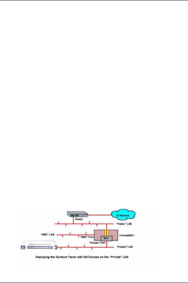
NATAccess™
NATAccess is an intelligent network address translation technology. It enables VoIP networks with multiple endpoints to operate behind firewalls equipped with H.323 Network Address Translation (NAT); this provides maximum network security. NATAccess simplifies deployment by eliminating the need to place the Tenor on a public IP network. Using NATAccess provides easy, secure expansion between multiple VoIP sites. In addition, NAT technology in the Tenor permits the use of private subnets at the same time; in-house calls will never go over the public internet.
Figure 1-3 Tenor with NATAccess Deployment
|
|
|
|
|
|
|
||||||||
|
|
|
|
Router |
|
|||||||||
|
|
|
|
|
|
|
|
|
|
|
|
|
|
|
|
|
|
“Public” LAN |
|
||||||||||
|
|
|
|
|
|
|
|
|
|
|
|
|
|
|
|
|
|
|
|
|
|
|
|
|
|
|
|||
|
“DMZ” LAN |
|
|
|
|
|
|
|
|
|
|
|
|
|
|
|
|
|
|
|
|
|
|
Firwall NAT |
|
||||
|
|
“DMZ” Port |
|
|
|
|
|
|||||||
|
|
|
|
|
|
|
|
|||||||
|
|
|
|
|
|
|
|
|
|
|
||||
|
|
|
|
|
|
|
|
|
|
|
||||
|
|
|
“Private” port |
|
||||||||||
|
|
|
|
|
|
|
|
|
|
|
|
|
|
|
|
|
|
“Private” LAN |
|
||||||||||
|
|
|
|
|
|
|
|
|
|
|
|
|
|
|
1-6 |
P/N 480-0062-00-10 |

Chapter 1: Overview
Dynamic Call Routing
Tenor AX’s intelligent call routing capabilities are state-of-the-art. The unit automatically detects and supports three call types: voice, fax, and modem.
Tenor AX will first identify the call origination site—Line/FXO, Phone/FXS, or IP routing group — and then route the call according to the parameters you have configured in the routing database. Each call may be routed via circuit switched path between any two circuit groups, or compressed and transported via VoIP when connecting to an IP routing group. Trunk circuits are those that typically connect to another circuit switched network such as the PSTN. Line circuits typically connect to a termination device on the user premises, such as a PBX.
P/N 480-0062-00-10 |
1-7 |

Chapter 1: Overview
Tenor AX Call Paths
Tenor AXM MultiPath Switch (AXM0800, AXM1600, AXM2400) Configuration
The Tenor AX VoIP MultiPath Switch Configuration is symmetrical with an equal number of Phone/FXS and Line/FXO ports. Calls are routed from the Phone/FXS, Line/FXO, or IP Network. Calls can be routed in any direction between any of the ports.
Below are descriptions of the basic call paths from the FXS (Phone), FXO (Line) and IP; the exact call path will be determined by the specific Tenor AX configuration you have in your network.
FXS (Phone) Originated Calls. Calls coming from the Phone/FXS interface (i.e.PBX) may be switched to either the data network as a VoIP call or to the FXO interface, typically for connection to another circuit switched network such as the PSTN. The routing decision made by the Tenor AX is based upon your configuration and the dialed number. See Figure 1-4 for an example of a call originated from a PBX.
Figure 1-4 FXS (Phone) Originated Calls
PBX |
FXS Port |
FXO Port |
|
PSTN |
|
Keyswitch |
|
|
Phone |
|
|
|
|
OR |
|
|
IP Network |
FXO (Line) Originated Calls. A call coming from a Line/FXO interface may be switched to either the data network as a VoIP call, a Line Circuit, or trunk typically for connection to a termination device on the user’s premises such as a PBX. The routing decision made by the Tenor AX is based upon your configuration and the dialed number. See Figure 1-5 for an example of a call originated from the PSTN.
Figure 1-5 FXO (Line) Originated Calls
PBX |
FXS Port |
FXO Port |
|
PSTN |
|
Keyswitch |
|
|
Phone |
|
|
OR 
IP Network
1-8 |
P/N 480-0062-00-10 |

Chapter 1: Overview
IP Network Calls. Calls coming from the IP network data can be routed to the Line/FXO or Phone/ FXS interfaces. The Tenor will route calls based upon the dialed number. If the number is configured as a local phone number, the call will be sent to a Phone/FXS circuit for termination, otherwise the call is considered a “Hop-Off call” and the Tenor sends it out through a Line/FXO interface, typically connected to the PSTN. See Figure 1-6 for an example of a call originated from the IP network.
Figure 1-6 IP Network Originated Calls
PBX
Keyswitch |
|
PSTN |
Phone |
|
|
|
|
|
FXS Port |
OR |
FXO Port |
|
IP Network
P/N 480-0062-00-10 |
1-9 |

Chapter 1: Overview
Tenor AXT Trunking VoIP Gateway (AXT0800, AXT1600, AXT2400) Configuration
The Tenor AXT Trunking VoIP Gateway Configuration is used for trunk side PSTN (Line/FXO port) to VoIP connections; calls coming from the Line/FXO interface (i.e.PSTN) may be switched to the data network as a VoIP call. Calls can be routed in any direction between any of the ports. See Figure 1-7 for an example of a call originating from the PSTN.
Figure 1-7 Tenor AXT FXO/Line Originated Call Sample
FXO Port
PSTN
IP Network
Tenor AXG VoIP Gateway (AXG0800, AXG1600, AXG2400) Configuration
The Tenor AXG VoIP Gateway Configuration is used for (Phone/FXS) to VoIP connections; calls coming from the Phone/FXS interface (i.e. PBX) may be switched as a VoIP call. Calls can be routed in any direction between any of the ports. See Figure 1-8 for an example of a call originating from the Phone/FXS side (PBX).
See Figure 1-8 for an example of a call originating from a PBX.
Figure 1-8 Tenor AXG Phone/FXS Originated Call Sample
FXS Port
PBX
Keyswitch
Phone
IP Network
1-10 |
P/N 480-0062-00-10 |

Chapter 1: Overview
Tenor AXE Enterprise VoIP Gateway (AXE0800, AXE1600, AXE2400) Configuration
The AXE Enterprise VoIP Gateway is mainly intended for applications interfacing between the PBX and the VoIP network, but it also includes two FXO ports for autoswitching PSTN back-up and 911 service provision. The number of VoIP ports is equal to the number of FXS ports. Calls can be routed in any direction between any of the ports.
See Figure 1-9 for an example of a call originating from a PBX.
Figure 1-9 Tenor AXE Phone/FXS Originated Call Sample
FXS Port |
FXO Port |
PBX |
PSTN |
Keyswitch |
|
Phone |
|
IP Network
P/N 480-0062-00-10 |
1-11 |
Chapter 1: Overview
Advanced Features/Capabilities
Call Management
There are four types of routing databases you can configure: Bypass Directory Numbers (BPN), Hunt Local Directory Numbers (Hunt LDN), Hop-Off Directory Numbers (HDN), and Static Routes.
Bypass Directory Numbers. Bypass Directory Numbers (BDN) are telephone numbers that are automatically routed directly from a line circuit to the PSTN; they will not be routed VoIP. Some examples of bypass numbers include toll-free calls, emergency calls (i.e., 911), or high security calls.
Hunt Local Directory Numbers. A Hunt Local Directory Number (Hunt LDN) is a phone number reachable through local Line Circuits.
Hop-Off Directory Number. A Hop-off PBX call travels over IP, and then “hops” off into the public network (PSTN) on the distant side to reduce or eliminate public toll charges (also known as Leaky Area Map). A Hop-Off Directory Number is routed over the IP to another Tenor location and then out to the Trunk circuit, possibly to the PSTN as a local call.
Static Routes. Static Routes are used between networks and other H.323 devices that are not registered to the network through the Border Element (such as non-Quintum gateways). A static route associates endpoints (as represented by their IP address) with Directory Number patterns.
Dial Plan Options
Public/Private Dial Plan Support.The Tenor AX supports public and private dial plans. A public dial plan includes numbers which conform to the international dialing plan (E.164) of a country code + city/area code + local number. For a public dial plan, you can define the numbering plan structure for the Tenor AX to use for outgoing calls.
A private dial plan does not conform to a public dialing plan (i.e., 3 digit dialing plan); through the Tenor AX you are able to configure the unique pattern/dialing plan structure, including number length.
You are able to configure which dial plan to use for incoming and outgoing calls, including whether other options such as hop-off calls, will use a public or private dial plan.
User Programmable Dial Plan Support. The User Programmable Dial Plan Support (UPDP) enables the Tenor to identify a completely customizable set of digit sequences, such as Local, National, International or Private Numbers.
PassThrough support for certain call types. Certain call types can be directly routed to a trunk circuit, without going IP. There are several routing tables you can configure through the Tenor Configuration Manager to adjust how the Tenor AX unit routes these types of “pass through” numbers. For example, you may want to configure 911 as a “bypass number”, which means that all 911 calls coming into Tenor AX from the line circuit will be routed directly to a Trunk circuit presumably connected to a PSTN. Bypass calls are never routed over IP.
P/N 480-0062-00-10 |
1-12 |

Chapter 1: Overview
Hop-off PBX Calls. Hop-off numbers are phone number patterns for calls to be routed out to the PSTN. (A hop-off PBX call is a toll call which hops through a private network to reduce or eliminate the toll charge.) They are entered in a Hop-off Number Directory and associated with trunks where matching calls should be sent.
Tenor AX supports those hop-off PBX calls where the destination Tenor AX is programmed to route the call to the PSTN. The destination Tenor AX unit is configured with the phone numbers to be “supported” for this feature.
H.323 Gatekeeper Services
The Tenor AX unit’s built-in H.323 gatekeeper performs IP call routing functions, such as call control and administrative services to another Tenor AX unit, or another H.323 endpoint. The gatekeeper’s functionality complies with the H.323 industry specifications for voice control and management.
Gatekeeper. A Gatekeeper in an H.323 network provides call control services and other services to H.323 endpoints (i.e., gateways, terminals, and MCUs). The Tenor AX has a built-in H.323 gatekeeper which complies to the H.323 industry specifications for voice control and management. The gatekeeper performs call routing functions for calls entering and exiting a site.
The Gatekeeper performs IP call routing functions, such as Call Control Signaling and Call Authorization for Gateways, IP phones, and H.323 terminals. The Gatekeeper communicates with other Gatekeepers through a Border Element. When using a group of Tenor AX units, you can assign one unit as the Gatekeeper for the network. We recommend you configure each as its own gatekeeper.
Tenor AX supports gatekeeper to gatekeeper communication using the standard LRQ (Location Request)/LCF (Location Confirm) messaging scheme.
Zone Management. A zone is a group of H.323 defined endpoints controlled by a Gatekeeper. Endpoints can be gateways (i.e., Tenor AX), terminals, and/or multipoint conferencing units (MCUs). Endpoints establish control channels with a gatekeeper for registration, admission, and security. Call routing information about the endpoint is sent to the gatekeeper, including: IP address, unit type (gateway, terminal, or MCU) and routing information (such as phone numbers, number patterns, etc.).
A collection of zones is an administrative domain. An administrative domain provides call routing services for its zones through gatekeeper to gatekeeper messages or gatekeeper to border element messages (see below for more information).
Call Registration. When registration from an H.323 endpoint is complete and a call is originated, the call request is sent to the gatekeeper. The call request provides the Gatekeeper with the dialed number and requests the routing information. The gatekeeper confirms the dialed number and supplies the endpoint with the destination IP address. For example, a Tenor AX’s gatekeeper will act as the gatekeeper for that zone and all of the other endpoints will register with it.
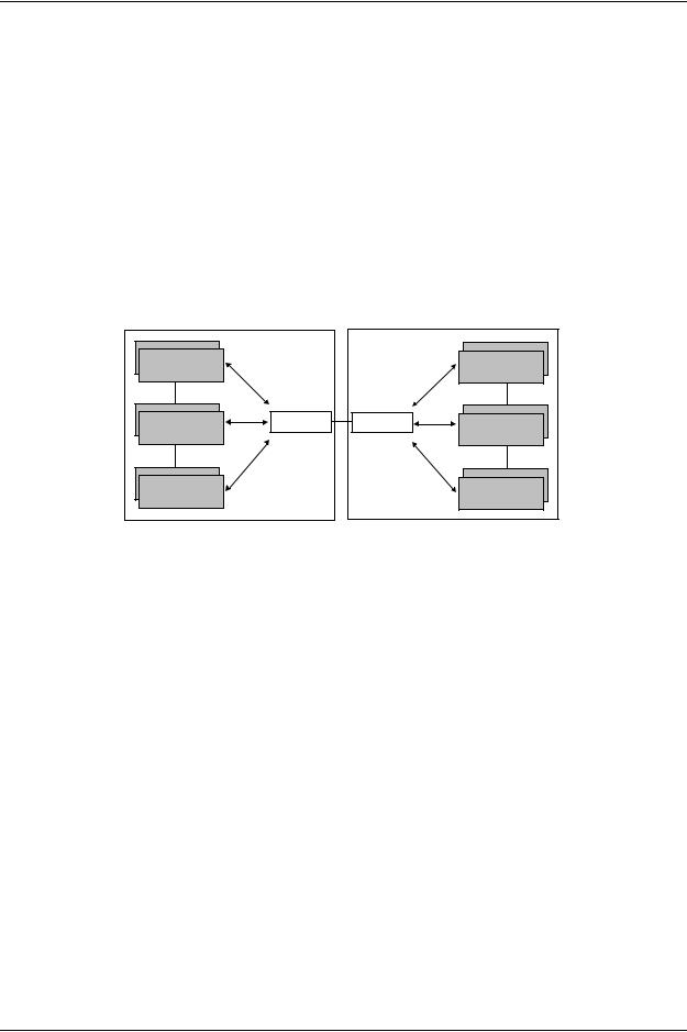
Border Element. The Tenor AX’s gatekeeper uses a border element to gain access to the routing database of the administrative domain for the purpose of call completion or any other services that involve communications with other endpoints out of the administrative domain. The border element functionality is built into the Tenor AX unit, along with the gateway and gatekeeper.
P/N 480-0062-00-10 |
1-13 |
Chapter 1: Overview
The primary function of the border element is to collect, manage, and distribute call routing information. A gatekeeper will establish a service relationship with a border element; the gatekeeper provides its zones capabilities and the border element shares call routing capabilities of other zones in the administrative domain. Through the border element, gatekeepers from multiple zones will be able to communicate.
A border element also establishes relationships with other border elements to route between administrative domains. If a gatekeeper cannot resolve an address, it contacts the border element.
In addition, if you are using more than one Tenor unit, you can configure one of the border elements for that zone. The Tenor AX unit can use two border elements: primary and secondary. These work together as one entity to provide redundancy and fault tolerance; there are no hierarchal differences.
Gatekeeper |
Gatekeeper |
Zone |
Zone |
Border Element |
Border Element |
Gatekeeper |
Gatekeeper |
Zone |
Zone |
Gatekeeper |
Gatekeeper |
Zone |
Zone |
Administrative Domain |
Administrative Domain |
Call Services. Gatekeepers provide services such as addressing, authorization and authentication of terminals and gateways, bandwidth management, accounting, billing, and charging. Gatekeepers also provide call-routing services. Specifically, the Tenor AX Gatekeeper provides the functions which follow:
Address Translation. The gatekeeper translates telephone numbers into IP addresses and vice versa. It performs Alias Address (phone number) to Transport Address (IP address) translation when an endpoint requests service. The Gatekeeper uses a translation table to translate an Alias Address (an address such as an H.323 identifier that a user may not understand) to a transport address. The translation table is updated using Registration messages.
Autodiscovery. The gatekeeper is discovered in one of the following ways: An endpoint sends an IP broadcast called a Gatekeeper Request message (GRQ) message (which includes that correct gatekeeper name) to discover a Gatekeeper OR the endpoint will discover a gatekeeper by its IP address.
Routing. The gatekeeper identifies the IP address of endpoints in its administrative domain. The gatekeeper builds a routing database from information obtained from the border element and also from gateways and H.323 endpoints.
Admissions Control. All H.323 endpoints must register and request permission to enter the gatekeeper’s zone; the gatekeeper will confirm or deny access to the network. The gatekeeper authorizes
P/N 480-0062-00-10 |
1-14 |

Chapter 1: Overview
network access and protects the integrity of the network using Admissions Request (ARQ), Admissions Confirmation (ACF) and Admissions Reject (ARJ) messages.
SIP User Agent
SIP (Session Initiation Protocol) is a signaling protocol used to establish a session on an IP network for voice control and management; it is a request-response protocol that closely resembles Hypertext Transfer Protocol (HTTP), which forms the basis of the World Wide Web. SIP re-uses many of the constructs and concepts of Internet protocols such as HTTP and Simple Mail Transfer Protocol (SMTP). The purpose of SIP is only to establish/change/terminate sessions. SIP is not concerned with the content or details of the session.
SIP is Transport layer-independent, which means it can be used with any transport protocol: UDP, TCP, ATM, etc. It is text-based, so it requires no encoding/decoding like H.323. And SIP supports user mobility, using proxies and redirecting requests to your current location.
When configured for SIP the Tenor will act as a SIP User Agent (Endpoint) as defined in IETF RFC3261. Multiple user agents allow for separate agents to be allocated to each SIP call. It will be able to gateway calls to and from the IP network, and Customer Premise Equipment (CPE) such as phones, PBX's, and FAX machines, or the Public Switched Telephone Network (PSTN). The Tenor SIP User Agent will work in conjunction with an external SIP proxy or redirect to route and connect calls over SIP based networks.
There are three basic components of SIP:
1.User Agent (Endpoint)
•client element, initiates calls
•server element, answers calls
2.Network Server (Proxy Server or Redirect Server)
•name resolution
•user location
•redirect and forking
3.Registrar
•Stores registration information in a location service using a non-SIP protocol.
P/N 480-0062-00-10 |
1-15 |

Chapter 2: Hardware Components
This chapter tells you what is contained in your hardware package. A description of each component is also included.
Specifically, the following topics are covered:
!Hardware Description
!Cables
!Specifications
P/N 480-0062-00-10 |
2-1 |

Chapter 2: Hardware Components
Hardware Description
The Tenor AX is a stackable device which provides Phone/FXO and Line/FXO connections as well as connections to the Ethernet LAN and a PC.
The unit’s front panel includes LEDs; the back panel includes connection jacks, a diagnostics option, a reset button, and an on/off power switch.
Front Panel Connections and Reset Options
Figure 2-1 Tenor AX Front Panel
Power LED
Status LED |
Analog Port LEDs |
|
LAN LEDs |
||
|
The LEDs display the health of the system. There are different types of LEDs: Power, Status, LAN, and Analog Ports. See Table 2-1 for a description.
Table 2-1 Front Panel LEDs Definitions
LED |
Label |
LED Color |
Description |
|
|
|
|
|
|
|
|
|
|
|
Power |
Power |
Green |
On: Indicates power is on. |
|
|
|
|
Off: Power is off. |
|
|
|
|
|
|
Status |
Status |
Green Flashing |
Operational Status. |
|
|
|
|
Off: Tenor AX is working properly. |
|
|
|
|
On: One or more diagnostic tests |
|
|
|
|
have failed. |
|
|
|
|
|
|
|
|
Line/FXO LED - Green |
On indicates activity is occurring |
|
|
Line/FXO |
|
on at least one Line/FXO port. |
|
Analog Ports |
Phone/FXS |
|
|
|
Phone/FXS LED - Green |
On indicates activity is occurring |
|||
|
|
|||
|
|
|
on at least one Phone/FXS port. |
|
|
|
|
|
2-2 |
P/N 480-0062-00-10 |

Chapter 2: Hardware Components
LED |
Label |
LED Color |
Description |
|
|
|
|
|
|
|
|
|
100Mb |
Green |
On: The advertised link rate is |
|
|
|
100Mb if the link is not connected, |
|
|
|
or the actual link rate is 100b if the |
|
|
|
link is connected. |
LAN |
|
|
Off: The advertised link rate is |
|
|
|
10Mb if the link is not connected, |
|
|
|
or the actual link rate is 10Mb if |
|
|
|
the link is connected. |
|
|
|
|
|
Link |
Green |
On: Link is working properly and |
|
|
|
there is activity on the line. |
|
|
|
Off: Link has failed. |
|
|
|
|
|
Activity |
Green Flashing |
On: Indicates there is activity (i.e., |
|
|
|
transmit/receive) on the line. |
|
|
|
Off: No activity is occurring. |
|
|
|
|
P/N 480-0062-00-10 |
2-3 |

Chapter 2: Hardware Components
Back Panel
Console |
|
Port |
Power Switch |
|
Phone/FXS port |
Line/FXO port |
|
Reset |
|
LAN port |
Diag |
Power |
|
Receptacle |
||
|
|
|
•Phone/FXS port. Provides a 50 Pin Telco connector which supports up to 24 Phone/FXS connections for connecting to the PBX, Keyphone or phones.
•Line/FXO port. Provides a 50 Pin Telco connector which supports up to 24 FXO/Line connections for connection to the Central Office (connection to the PSTN).
•LAN port. 10/100 Base-T Ethernet port. This port provides an RJ-45 jack for individual connection to a 10/100 Ethernet LAN switch or hub via RJ-45 cable; it is individually configured with a unique IP and MAC address.
Figure 2-2 10/100 BASE-T Ethernet Port Pin Order
Table 2-2 Input/Output 10/100 Ethernet port
Pin # |
Signal |
Definition |
Color |
|
|
|
|
|
|
|
|
1 |
TX + |
Transmit Data |
White w/orange |
|
|
|
|
2 |
TX - |
Transmit Data |
Orange |
|
|
|
|
3 |
RX + |
Receive Data |
White w/green |
|
|
|
|
4 |
RSVD |
Reserved |
Blue |
|
|
|
|
5 |
RSVD |
Reserved |
White w/blue |
|
|
|
|
6 |
RX - |
Receive Data |
Green |
|
|
|
|
7 |
RSVD |
Reserved |
White w/Brown |
|
|
|
|
2-4 |
P/N 480-0062-00-10 |

|
|
|
|
Chapter 2: Hardware Components |
||
|
|
|
|
|
|
|
|
Pin # |
Signal |
Definition |
|
Color |
|
|
|
|
|
|
|
|
|
|
|
|
|
|
|
|
8 |
RSVD |
Reserved |
|
Brown |
|
|
|
|
|
|
|
|
•Console port. This RS-232 connector is used for connection to a PC’s serial port via DB-9 serial cable at 38400 BPS 8N1, without flow control. The input/output signals are listed in Table 2-3.
Figure 2-3 DB-9 Female Connector Pin Order
5 4 3 2 1
9 8 7 6
Table 2-3 Serial RS232 DB-9 Connector Pinouts
Pin # |
Function |
Description |
|
|
|
|
|
|
1 |
DTR |
Data Terminal Ready |
|
|
|
2 |
TXD |
Transmit Data |
|
|
|
3 |
RXD |
Receive Data |
|
|
|
4 |
CD |
Carrier Detect |
|
|
|
5 |
GND |
Signal Ground |
|
|
|
6 |
N.C. |
No Connect |
|
|
|
7 |
N.C. |
No Connect |
|
|
|
8 |
N.C. |
No Connect |
|
|
|
9 |
N.C. |
No Connect |
|
|
|
•Diag. Enables you to perform software diagnostic procedures.
•Reset. Enables you to reset the system. See Chapter 5: Advanced Topic: Diagnostics/Maintenance for more information.
•Power Switch. Switch to turn power on and off.
•Power Receptacle. Connection port for connection to an AC outlet for power.
P/N 480-0062-00-10 |
2-5 |

Chapter 2: Hardware Components
Cables
The cables listed in Table 2-4 are required to connect a Tenor AX to various interfaces. Contact Quintum for ordering information, if necessary.
Table 2-4 Cables Supported |
|
|
|
Cable |
Usage |
|
|
|
|
50-Pin Telco Connector |
Connection to FXO/Line |
|
Connection to FXS/Phone |
|
|
RJ-45 Ethernet cable |
Connection to Ethernet LAN 10/100 |
|
|
DB-9 Serial RS-232 |
Connection to PC’s asynchronous console port |
|
|
Detachable (IEC) AC Power Supply Cord |
Connection to AC power jack. |
|
|
2-6 |
P/N 480-0062-00-10 |
Loading...