

Page 1

®
Tenor Call Relay 60
d
G
t
u
N
d
c
0
0
7
4
8
6
0
-
r
o
P
P
/
71 James Way
Eatontown, NJ 07724 USA
1-877-SPEAK-IP
1-732-460-9000
1-732-544-9119 (fax)
u
-
0
0
e
i
0
-
0
Tenor and Quintum are registered trademarks. Call Relay SP, PacketSaver, Quintum Technologies, Inc.,
VoIP Made Easy, TASQ, SelectNet, and SelectNet Technology are trademarks of Quintum Technologies,
Inc.
Page 2

Table of Contents
About this Guide
What’s included? . . . . . . . . . . . . . . . . . . . . . . . . . . . . . . . . . . . . . . . . . . . . . . . . . . . . . . . . . 1-2
Typographical Conventions . . . . . . . . . . . . . . . . . . . . . . . . . . . . . . . . . . . . . . . . . . . . . . . . . 1-3
Product Guide Conventions . . . . . . . . . . . . . . . . . . . . . . . . . . . . . . . . . . . . . . . . . . . . . 1-3
Finding Help. . . . . . . . . . . . . . . . . . . . . . . . . . . . . . . . . . . . . . . . . . . . . . . . . . . . . . . . . . . . . 1-4
Chapter 1: Overview
What is Tenor® Call Relay 60? . . . . . . . . . . . . . . . . . . . . . . . . . . . . . . . . . . . . . . . . . . . . . . 1-2
Features and Capabilities . . . . . . . . . . . . . . . . . . . . . . . . . . . . . . . . . . . . . . . . . . . . . . . . . . 1-3
State of the art Management system . . . . . . . . . . . . . . . . . . . . . . . . . . . . . . . . . . . . . . 1-3
Direct Connection Between VoIP Networks. . . . . . . . . . . . . . . . . . . . . . . . . . . . . . . . . 1-3
NATAccess™ supports all VoIP endpoints behind firewall . . . . . . . . . . . . . . . . . . . . . 1-4
Remove Unnecessary Call Delay . . . . . . . . . . . . . . . . . . . . . . . . . . . . . . . . . . . . . . . . 1-4
Voice Control Management . . . . . . . . . . . . . . . . . . . . . . . . . . . . . . . . . . . . . . . . . . . . . 1-5
H.323 Gatekeeper . . . . . . . . . . . . . . . . . . . . . . . . . . . . . . . . . . . . . . . . . . . . . . . . . . . . 1-5
Session Initiation Protocol (SIP) . . . . . . . . . . . . . . . . . . . . . . . . . . . . . . . . . . . . . . . . . 1-5
H.323/SIP Signaling Translation . . . . . . . . . . . . . . . . . . . . . . . . . . . . . . . . . . . . . . . . . 1-6
Provides Load Balancing . . . . . . . . . . . . . . . . . . . . . . . . . . . . . . . . . . . . . . . . . . . . . . . 1-7
SNMP Support . . . . . . . . . . . . . . . . . . . . . . . . . . . . . . . . . . . . . . . . . . . . . . . . . . . . . . . 1-7
Call Relay 60 communication . . . . . . . . . . . . . . . . . . . . . . . . . . . . . . . . . . . . . . . . . . . 1-7
Easy Connect to Console . . . . . . . . . . . . . . . . . . . . . . . . . . . . . . . . . . . . . . . . . . . . . . 1-7
Capabilities . . . . . . . . . . . . . . . . . . . . . . . . . . . . . . . . . . . . . . . . . . . . . . . . . . . . . . . . . . . . . 1-8
Single Point of Network Interconnection . . . . . . . . . . . . . . . . . . . . . . . . . . . . . . . . . . . 1-8
PacketSaver™ . . . . . . . . . . . . . . . . . . . . . . . . . . . . . . . . . . . . . . . . . . . . . . . . . . . . . . . 1-9
Call Detail Recording . . . . . . . . . . . . . . . . . . . . . . . . . . . . . . . . . . . . . . . . . . . . . . . . . . 1-9
Network Administration and Accounting . . . . . . . . . . . . . . . . . . . . . . . . . . . . . . . . . . . 1-10
Call Relay 60 with Tenor MultiPath Switch . . . . . . . . . . . . . . . . . . . . . . . . . . . . . . . . . 1-11
Chapter 2: Hardware Components
Hardware Description . . . . . . . . . . . . . . . . . . . . . . . . . . . . . . . . . . . . . . . . . . . . . . . . . . . . . 2-2
Front Panel Connections and Reset/Diag Options . . . . . . . . . . . . . . . . . . . . . . . . . . . 2-2
Front Panel LEDs. . . . . . . . . . . . . . . . . . . . . . . . . . . . . . . . . . . . . . . . . . . . . . . . . . . . . 2-4
Back Panel. . . . . . . . . . . . . . . . . . . . . . . . . . . . . . . . . . . . . . . . . . . . . . . . . . . . . . . . . . 2-5
Cables . . . . . . . . . . . . . . . . . . . . . . . . . . . . . . . . . . . . . . . . . . . . . . . . . . . . . . . . . . . . . . . . . 2-6
DB-9 Serial RS-232 Cable . . . . . . . . . . . . . . . . . . . . . . . . . . . . . . . . . . . . . . . . . . . . . . 2-8
Specifications. . . . . . . . . . . . . . . . . . . . . . . . . . . . . . . . . . . . . . . . . . . . . . . . . . . . . . . . . . . . 2-9
P/N 480-0076-00-00 1-1
Page 3

Voice/Fax . . . . . . . . . . . . . . . . . . . . . . . . . . . . . . . . . . . . . . . . . . . . . . . . . . . . . . . . . . . 2-9
LAN Connection. . . . . . . . . . . . . . . . . . . . . . . . . . . . . . . . . . . . . . . . . . . . . . . . . . . . . . 2-9
Physical . . . . . . . . . . . . . . . . . . . . . . . . . . . . . . . . . . . . . . . . . . . . . . . . . . . . . . . . . . . . 2-9
Electrical . . . . . . . . . . . . . . . . . . . . . . . . . . . . . . . . . . . . . . . . . . . . . . . . . . . . . . . . . . . 2-9
Environmental . . . . . . . . . . . . . . . . . . . . . . . . . . . . . . . . . . . . . . . . . . . . . . . . . . . . . . . 2-9
Chapter 3: Installation
Installation . . . . . . . . . . . . . . . . . . . . . . . . . . . . . . . . . . . . . . . . . . . . . . . . . . . . . . . . . . . . . . 3-2
Pre-Installation Guidelines . . . . . . . . . . . . . . . . . . . . . . . . . . . . . . . . . . . . . . . . . . . . . . 3-2
Inspect Package Contents . . . . . . . . . . . . . . . . . . . . . . . . . . . . . . . . . . . . . . . . . . . . . . 3-2
Rack Install . . . . . . . . . . . . . . . . . . . . . . . . . . . . . . . . . . . . . . . . . . . . . . . . . . . . . . . . . 3-3
Connection. . . . . . . . . . . . . . . . . . . . . . . . . . . . . . . . . . . . . . . . . . . . . . . . . . . . . . . . . . . . . . 3-6
Connect to Ethernet LAN . . . . . . . . . . . . . . . . . . . . . . . . . . . . . . . . . . . . . . . . . . . . . . . 3-6
Connect to PC Console . . . . . . . . . . . . . . . . . . . . . . . . . . . . . . . . . . . . . . . . . . . . . . . . 3-7
Install Ground Cable (if required). . . . . . . . . . . . . . . . . . . . . . . . . . . . . . . . . . . . . . . . . . . . . 3-8
Power up the System. . . . . . . . . . . . . . . . . . . . . . . . . . . . . . . . . . . . . . . . . . . . . . . . . . . . . . 3-9
Assign IP Address . . . . . . . . . . . . . . . . . . . . . . . . . . . . . . . . . . . . . . . . . . . . . . . . . . . . . . . . 3-10
Load Software Upgrade. . . . . . . . . . . . . . . . . . . . . . . . . . . . . . . . . . . . . . . . . . . . . . . . . . . . 3-11
Chapter 4: Getting Started with Configuration
Getting Started with Configuration/Monitoring . . . . . . . . . . . . . . . . . . . . . . . . . . . . . . . . . . . 4-2
Tenor Configuration Manager . . . . . . . . . . . . . . . . . . . . . . . . . . . . . . . . . . . . . . . . . . . 4-2
Tenor Monitor. . . . . . . . . . . . . . . . . . . . . . . . . . . . . . . . . . . . . . . . . . . . . . . . . . . . . . . . 4-3
Command Line Interface . . . . . . . . . . . . . . . . . . . . . . . . . . . . . . . . . . . . . . . . . . . . . . . 4-3
Chapter 5: System Alarms
Monitor Alarms. . . . . . . . . . . . . . . . . . . . . . . . . . . . . . . . . . . . . . . . . . . . . . . . . . . . . . . . . . . 5-2
How to Read Alarms . . . . . . . . . . . . . . . . . . . . . . . . . . . . . . . . . . . . . . . . . . . . . . . . . . 5-2
Valid Alarms. . . . . . . . . . . . . . . . . . . . . . . . . . . . . . . . . . . . . . . . . . . . . . . . . . . . . . . . . 5-4
View Alarms. . . . . . . . . . . . . . . . . . . . . . . . . . . . . . . . . . . . . . . . . . . . . . . . . . . . . . . . . . . . . 5-6
Display all Alarms . . . . . . . . . . . . . . . . . . . . . . . . . . . . . . . . . . . . . . . . . . . . . . . . . . . . 5-6
Display Active Alarms . . . . . . . . . . . . . . . . . . . . . . . . . . . . . . . . . . . . . . . . . . . . . . . . . 5-6
Display Alarm History. . . . . . . . . . . . . . . . . . . . . . . . . . . . . . . . . . . . . . . . . . . . . . . . . . 5-7
Chapter 6: Diagnostics/Maintenance
Before you Begin . . . . . . . . . . . . . . . . . . . . . . . . . . . . . . . . . . . . . . . . . . . . . . . . . . . . . . . . . 6-2
Monitor LEDs . . . . . . . . . . . . . . . . . . . . . . . . . . . . . . . . . . . . . . . . . . . . . . . . . . . . . . . . . . . . 6-2
Diagnostics . . . . . . . . . . . . . . . . . . . . . . . . . . . . . . . . . . . . . . . . . . . . . . . . . . . . . . . . . . . . . 6-3
Common Symptoms/Problems . . . . . . . . . . . . . . . . . . . . . . . . . . . . . . . . . . . . . . . . . . 6-3
Verify Unit Provisioning . . . . . . . . . . . . . . . . . . . . . . . . . . . . . . . . . . . . . . . . . . . . . . . . 6-3
Ping Unit . . . . . . . . . . . . . . . . . . . . . . . . . . . . . . . . . . . . . . . . . . . . . . . . . . . . . . . . . . . 6-4
Monitor Alarms. . . . . . . . . . . . . . . . . . . . . . . . . . . . . . . . . . . . . . . . . . . . . . . . . . . . . . . . . . . 6-4
P/N 480-0076-00-00 1-2
Page 4

Alarms . . . . . . . . . . . . . . . . . . . . . . . . . . . . . . . . . . . . . . . . . . . . . . . . . . . . . . . . . . . . . 6-4
General Maintenance . . . . . . . . . . . . . . . . . . . . . . . . . . . . . . . . . . . . . . . . . . . . . . . . . . . . . 6-4
Restore Factory Defaults . . . . . . . . . . . . . . . . . . . . . . . . . . . . . . . . . . . . . . . . . . . . . . . 6-4
Reset System. . . . . . . . . . . . . . . . . . . . . . . . . . . . . . . . . . . . . . . . . . . . . . . . . . . . . . . . 6-4
Change Password . . . . . . . . . . . . . . . . . . . . . . . . . . . . . . . . . . . . . . . . . . . . . . . . . . . . 6-4
Change Unit Date and Time . . . . . . . . . . . . . . . . . . . . . . . . . . . . . . . . . . . . . . . . . . . . 6-5
If you need Additional Help . . . . . . . . . . . . . . . . . . . . . . . . . . . . . . . . . . . . . . . . . . . . . . . . . 6-5
Warranty/Approvals
Documentation Notice
GLOSSARY
INDEX
P/N 480-0076-00-00 1-3
Page 5

About this Guide
What’s included?
Typographical Conventions
Finding Help
P/N 480-0076-00-00 Preface-1
Page 6

What’s included?
This product guide is divided into chapters; each chapter describes a specific topic. The following chapters are included:
• About this Guide: Describes what is included in the product guide, including typographical
conventions.
• Chapter 1: Overview: Includes a general overview of the product, including features and how
the Call Relay 60 product fits into your network.
• Chapter 2: Hardware Components: Hardware description.
• Chapter 3: Installation. Describes how to install the Call Relay 60 unit, including how to set
the IP address.
• Chapter 4: Getting Started with Configuration. Includes information for accessing the Command Line Interface (CLI) and Tenor Configuration Manager.
• Chapter 5: System Alarms. Describes how to use the Alarm Manager and tells you how to view
alarms via telnet session.
About this Guide
• Chapter 6: Diagnostic/Maintenance. Describes how to troubleshoot and monitor the health of
the system.
• Warranty/Approvals
• Glossary
• Index
P/N 480-0076-00-00 Preface-2
Page 7

Typographical Conventions
Product Guide Conventions
Certain typographical conventions are used throughout this product guide. See below.
• All commands you enter via keystrokes appear in bold (e.g., Press Enter or Press Ctrl-I).
• All text commands you enter via Telnet session or command line typing appear in italics (e.g.,
type active).
• All references appear in italics (i.e., Choose File> Open).
• There are three types of special text that are designed to reveal supplemental information: Note,
Warning, and Caution. See below.
NOTE provides additional, helpful information. This information may tell you how to do a certain task or just be a reminder for how-to’s given in previous sections. (i.e., For a list of valid
commands at any time, type ?)
A WARNING provides information about how to avoid harm to your VoIP equipment or other
equipment. (i.e., Do not stack more than 4 units together.)
About this Guide
•A CAUTION provides information about how to avoid injury to yourself or to others. (i.e., Do
not install the equipment during a lightning storm.)
P/N 480-0076-00-00 Preface-3
Page 8

Finding Help
For additional help regarding configuration, see Chapter 4: Getting Started with Configura-
tion.
About this Guide
P/N 480-0076-00-00 Preface-4
Page 9

Chapter 1: Overview
This chapter gives you a general overview of the Call Relay 60, including feature descriptions and
capabilities.
Specifically, the following topics are covered:
Tenor Call Relay description
Features
Capabilities
P/N 480-0076-00-00 1-1
Page 10
Chapter 1: Overview
What is Tenor® Call Relay 60?
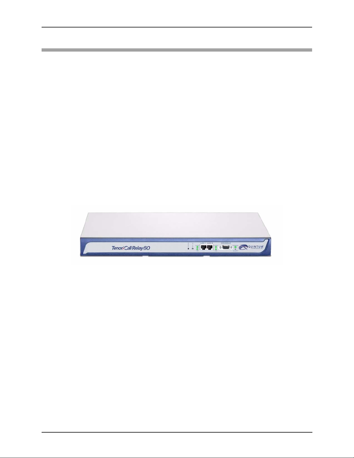
The Call Relay 60 Session Border Controller is a stand-alone unit which acts as an inter-domain
VoIP portal used to directly connect (over IP) one or more VoIP networks, supporting up to 60
simultaneous calls between networks. Call Relay 60 provides a single point for call control manage
ment, administrative services, call accounting, and security. All calls are switched through multiple
IP networks with just one single compression and decompression of the voice.
The unit connects with the IP network via 10/100 Mbps Ethernet connection; calls are transmitted
through the Ethernet LAN and routed over the corporate WAN or internet. It routes the call accord
ing to the parameters or defaults you have configured in the routing database.
Call Relay 60 features NATAccess, an intelligent network address translation technology. This
enables a VoIP network with multiple H.323/SIP endpoints to operate behind firewalls equipped
with Network Access Translation (NAT). NATAccess solves the problems commonly experienced
when using H.323/SIP devices behind firewalls; it eliminates the need to place these endpoints in
the “DMZ” or public IP domain, or to open the firewall to the point where serious security concerns
are raised. Call Relay 60 enables enterprises to expand their VoIP networks to home offices, branch
offices, customers, partners, and across the public Internet.
-
-
Figure 1-1 Call Relay 60
P/N 480-0076-00-00 1-2
Page 11
Chapter 1: Overview
Features and Capabilities
State of the art Management system
The Call Relay 60 is managed by the Tenor Configuration Manager and Tenor Monitor. Through the
Tenor Configuration Manager, you can configure all options. An easy-to-use Java-based installation
process enables you to install the manager and start configuring within minutes. Through the Ten or
Monitor, you can monitor the activity level and status of the system’s active calls, including alarms,
call detail records, etc. Both the Tenor Configuration Manager and Tenor Monitor provide compre
hensive on-line help systems that are available at your fingertips.
In addition, you can configure the unit through the Command Line Interface (CLI). Through this
simple telnet session, you can access all configuration options, including an online help system,
built into the CLI, which provides help for all features and functions. Just type help with the com
mand name at any prompt, and data about that field will be displayed.
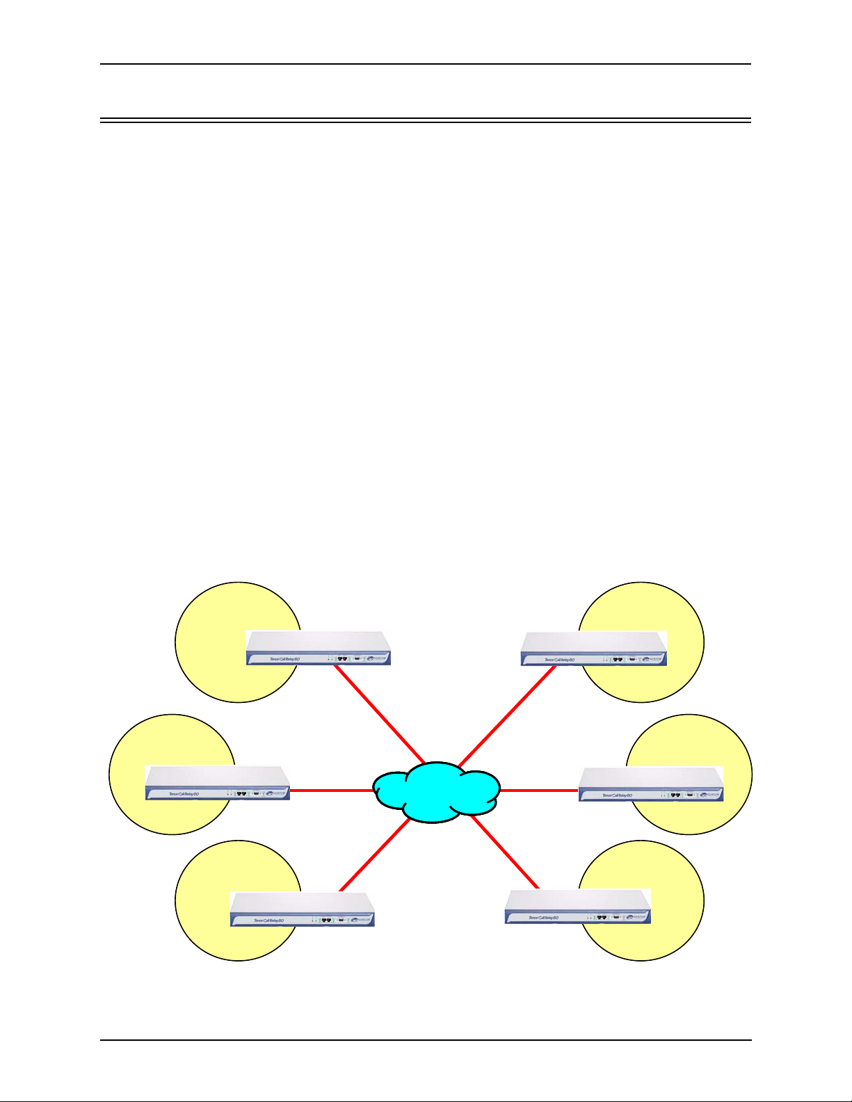
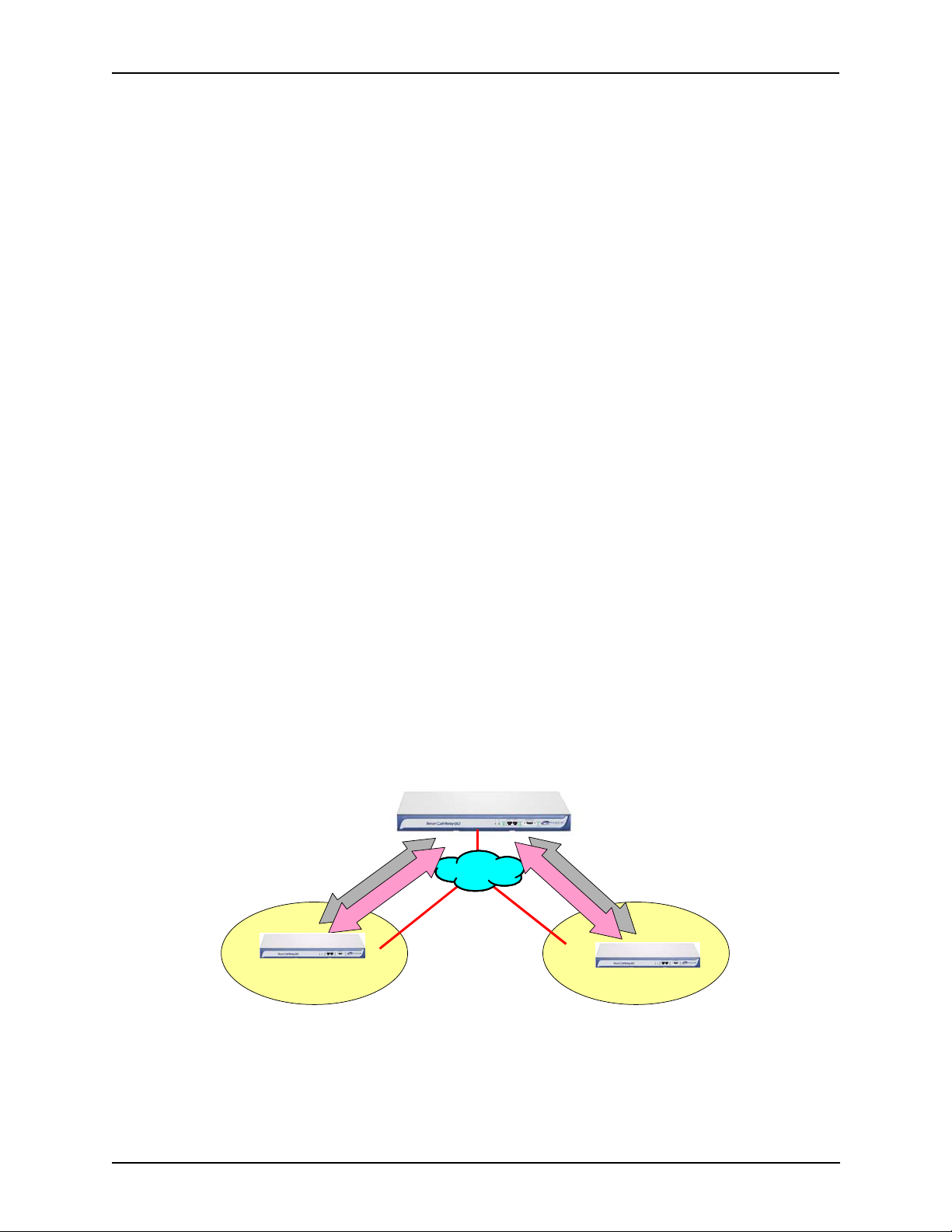
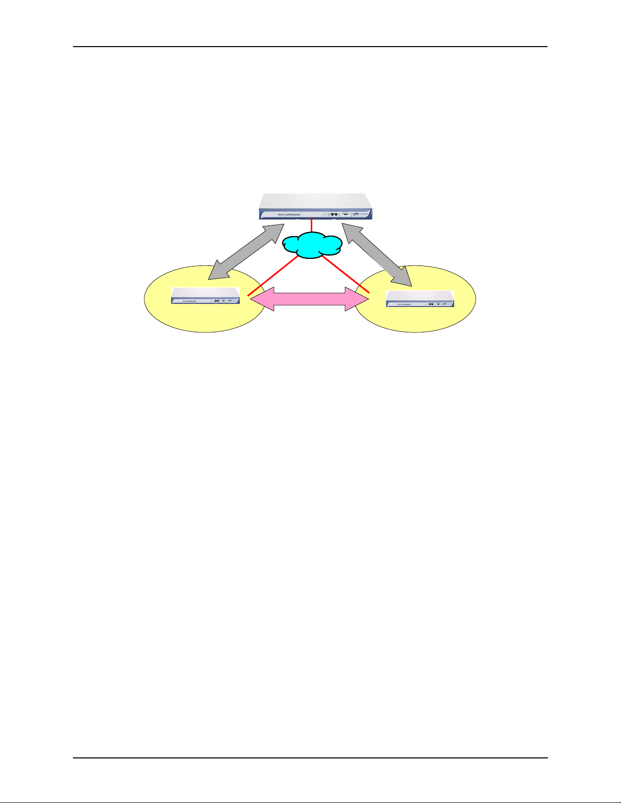
Direct Connection Between VoIP Networks
As an inter-domain portal, the Call Relay 60 switch provides direct IP connection between multiple
networks. The switch eliminates the need to link two or more VoIP networks via PSTN gateways.
Figure 1-2.
See
-
-
A direct connection between VoIP networks provides lower latency and the best possible voice quality by eliminating multiple compression/decompression steps when linking multiple VoIP networks.
VoIP Network A
VoIP Network A
Call Relay 60
Call Relay 60
VoIP Network B
VoIP Network B
Call Relay 60
Call Relay 60
VoIP Network C
VoIP Network C
Figure 1-2
Direct IP Connection via Call Relay 60
IP Network
IP NetworkIP Network
VoIP Network D
VoIP Network D
Call Relay 60
Call Relay 60
VoIP Network E
VoIP Network E
Call Relay 60
Call Relay 60
VoIP Network F
VoIP Network F
Call Relay 60
Call Relay 60
Call Relay 60
Call Relay 60
P/N 480-0076-00-00 1-3
Page 12
Chapter 1: Overview
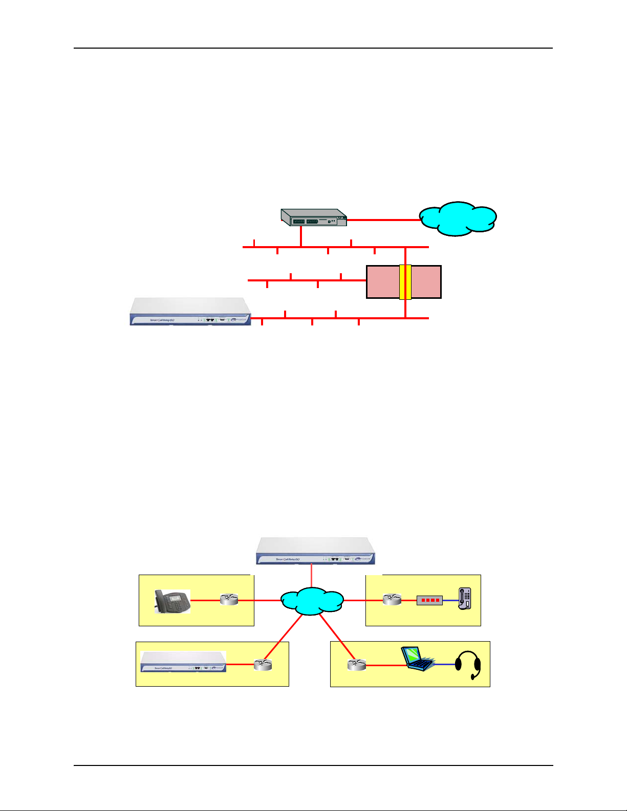
NATAccess™/Remote NAT support
NATAccess™ is an intelligent network address translation technology. It enables H.323-based and/
or SIP based VoIP networks to operate behind firewalls equipped with Network Access Translation
(NAT); this provides maximum network security. NATAccess simplifies deployment and installation
by eliminating the need to place the Call Relay 60 on a public IP network. Using NATAccess pro
-
vides an easy, secure expansion between multiple VoIP sites.
Figure 1-3
“DMZ” LAN
Deploying the Quintum Tenor with NATAccess on the “Private” LAN
NATAccess
RouterRouter
“DMZ” Port
IP NetworkIP Network
“Public” LAN
Firewall/NATFirewall/NAT
“Private” Port
“Private” LAN
The Remote NAT feature enables Tenors with SIP applications to be used in an environment where
endpoints are behind NAT firewalls. As long as a Call Relay 60 is placed in the public IP domain, it
can communicate transparently with any VoIP endpoint (even from other vendors) that is located
behind a NAT firewall. In the case of a NAT firewall application, the actual IP address and port
number that the call comes from is the public (WAN) IP address of the NAT/firewall/router.
Figure 1-4
Remote NAT
Call Relay 60
Call Relay 60
Call Relay 60
SIP Phone
Tenor
NAT/Router
NAT/Router
IP NetworkIP Network
NAT/Router
NAT/Router
PC SIP Client
T/A
Phone
P/N 480-0076-00-00 1-4
Page 13
Chapter 1: Overview
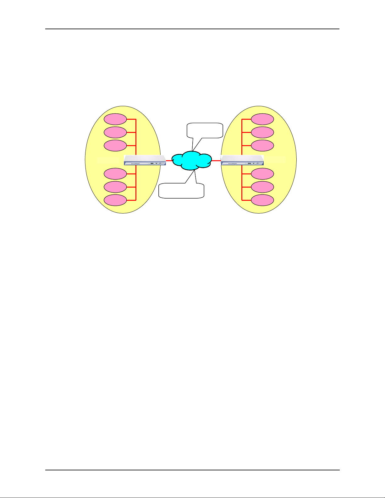
Remove Unnecessary Call Delay
Since redundant decompression and re-compressions processes are eliminated as a result of Call
Relay 60 (linking two VoIP networks via PSTN gateways is not required); this improves voice qual
ity by removing unnecessary delay, latency, and distortion.
-
Figure 1-5
VoIP
VoIP
VoIP
Endpoint
Endpoint
Endpoint
VoIP
VoIP
VoIP
Endpoint
Endpoint
Endpoint
VoIP
VoIP
VoIP
Endpoint
Endpoint
Endpoint
Call Relay 60
Call Relay Call Relay
Call Relay Call Relay
VoIP
VoIP
VoIP
Endpoint
Endpoint
Endpoint
VoIP
VoIP
VoIP
Endpoint
Endpoint
Endpoint
VoIP
VoIP
VoIP
Endpoint
Endpoint
Endpoint
VoIP Network A VoIP Network B
VoIP Network A VoIP Network B
Removes Unnecessary Call Delay
Endpoint
Endpoint
Endpoint
IP Used to Link
IP Used to Link
Networks
IP Network
IP NetworkIP Network
Eliminates
Eliminates
redundant encoding
redundant encoding
and decoding
and decoding
Networks
Endpoint
Endpoint
Endpoint
Endpoint
Endpoint
Endpoint
Endpoint
Endpoint
Endpoint
Endpoint
Endpoint
Endpoint
Endpoint
Endpoint
Endpoint
VoIP
VoIP
VoIP
VoIP
VoIP
VoIP
VoIP
VoIP
VoIP
Call Relay 60
VoIP
VoIP
VoIP
VoIP
VoIP
VoIP
VoIP
VoIP
VoIP
Voice Control Management
H.323 Gatekeeper
The Call Relay 60 complies with the H.323 industry specifications for voice control and management. It performs IP call routing functions (for calls entering and exiting a site). The Gatekeeper
(internal to a Call Relay 60) collects, manages, and distributes call routing information. The Border
Element (internal to the Call Relay 60) provides access into or out of an administrative domain.
Other H.323 endpoints, such as gateways, can register to the internal Gatekeeper.
Session Initiation Protocol (SIP)
SIP (Session Initiation Protocol) is a signaling protocol used to establish a session on an IP network
for voice control and management; it is a request-response protocol that closely resembles Hypertext
Transfer Protocol (HTTP), which forms the basis of the World Wide Web. SIP re-uses many of the
constructs and concepts of Internet protocols such as HTTP and Simple Mail Transfer Protocol
(SMTP). The purpose of SIP is only to establish/change/terminate sessions. SIP is not concerned
with the content or details of the session.
SIP is Transport layer-independent, which means it can be used with any transport protocol: UDP,
TCP, ATM, etc. It is text-based, so it requires no encoding/decoding like H.323. And SIP supports
user mobility, using proxies and redirecting requests to your current location.
When configured for SIP the Call Relay 60 will act as a SIP User Agent (Endpoint) as defined in
IETF RFC3261. Multiple user agents allow for separate agents to be allocated to each SIP call. It
will be able to direct calls to and from the IP network, and Customer Premise Equipment (CPE) such
P/N 480-0076-00-00 1-5
Page 14
Chapter 1: Overview
as phones, PBX's, and FAX machines, or the Public Switched Telephone Network (PSTN). The Call
Relay 60 SIP User Agent will work in conjunction with an external SIP proxy or redirect server to
route and connect calls over SIP based networks.
There are three basic components of SIP:
1. User Agent (Endpoint)
• client element, initiates calls
• server element, answers calls
2. Network Server (Proxy Server or Redirect Server)
• name resolution
• user location
• redirect and forking
3. Registrar
• Stores registration information in a location service using a non-SIP protocol.
H.323/SIP Signaling Translation
Through the Call Relay 60, there are two signaling options provided: H.323/SIP Signaling Translation and Signaling Gateway with Direct Media Connection. See below for a description of each.
H.323/SIP Signaling Translation. This enables the signaling and media (voice) to be sent from
the network (whether H.323 or SIP based) to the Call Relay 60 and out to another network (whether
H323 or SIP-based). The signaling is translated (from H.323 to SIP or vice versa) if necessary; this
simplifies inter-networking between diverse VoIP networks.
Figure 1-6
H.323 Based Network
H323/SIP Signaling Translation
3
2
3
a
.
i
d
H
e
M
IP NetworkIP Network
M
Call Relay 60
S
I
e
P
d
i
a
SIP Based Network
Signaling Gateway with Direct Media Connection. Enables signaling to be passed through
the Call Relay 60, then media (voice) is streamed directly between the network endpoints. In cases
where the origination network, the Call Relay, and destination network are in three different geo
-
graphical areas, this feature decreases delay time in voice media by sending it between the origina-
P/N 480-0076-00-00 1-6
Page 15
Chapter 1: Overview
tion and termination networks directly, rather than having it run out of the origination network,
through the Call Relay 60 and back out to the destination network.
In this mode, the Call Relay 60 can support up to a maximum of 90 simultaneous calls when used as
an H.323 signaling gateway (this mode of operation is known as the “Gatekeeper Routed Call
Mode”); endpoints can register to the Call Relay 60’s gatekeeper.
Figure 1-7
Signaling Gateway with Direct Media Connection (for H.323)
Call Relay 60
H
H
.
3
.
2
3
3
2
/
3
S
I
P
VoIP Network B
VoIP Network A
P
I
3
S
2
/
3
3
.
2
3
H
.
H
IP NetworkIP Network
Media
Provides Load Balancing
Using multiple Call Relay 60 units provides a way for load balancing. For example, one unit can be
used as a primary portal and another as a secondary portal. You can divide the calls between portals
or simply use one as a backup. In the event of an IP link failure, the redundancy offers maximum
reliability.
SNMP Support
The Call Relay 60 supports Simple Network Management Protocol (SNMP), the standard protocol
used to exchange network information between different types of networks. The Call Relay 60 acts
as an SNMP agent to receive commands and issue responses to the network manager. The network
manager will then be able to perform certain functions, such as generating and sending traps.
Call Relay 60 communication
The Call Relay 60 provides a single IP address for accessing the public IP network.
Easy Connect to Console
Plugging a DB-9 cable provided by Quintum between a PC and the unit’s asynchronous RS-232 port
will connect the unit and get you up and running. Through this port, you are able to configure an IP
address for the Call Relay 60 portal.
P/N 480-0076-00-00 1-7
Page 16
Chapter 1: Overview
Capabilities
Single Point of Network Interconnection
The Call Relay 60 aggregates all the traffic from the various IP endpoints and gateways within the
network and passes it to an endpoint at the “edge” of the another network, such as another Call
Relay 60 unit, IP phone or gateway. See
Figure 1-8.
Figure 1-8
VoIP Gateways
SD
Cisco AS5300
SERIES
VoIP Gateways
SD
Cisco AS5300
SERIES
Cisco AS5300
SERIES
Cisco AS5300
SERIES
Single Point for Network Access and Administration
Tenor VoIP Switch
SD
IPIP
SD
Call Relay SP
60
Call Relay SP
Tenor VoIP Switch
60
In each case, the Call Relay 60 provides a single IP address for entry to the complete network and
provides isolation between the networks in such a way that the internal structure of each remains
anonymous to the other. All voice calls and inter-network management function, including call man
agement, administration, and call accounting, to pass over the single inter-network IP connection. A
complete Call Detail Record (CDR) is generated by every call passing through the Call Relay 60 in
each direction. This simplifies the process of cross billing between customers. Each partner can
compile data on traffic entering and exiting their network; they are then able to generate and audit
inter-company billing.
A innovative method of linking VoIP networks is to use the Call Relay 60 approach to interconnect
the networks and perform call management. This also takes advantage of the Packet Saver feature,
which minimizes bandwidth usage.
-
P/N 480-0076-00-00 1-8
Page 17
Chapter 1: Overview
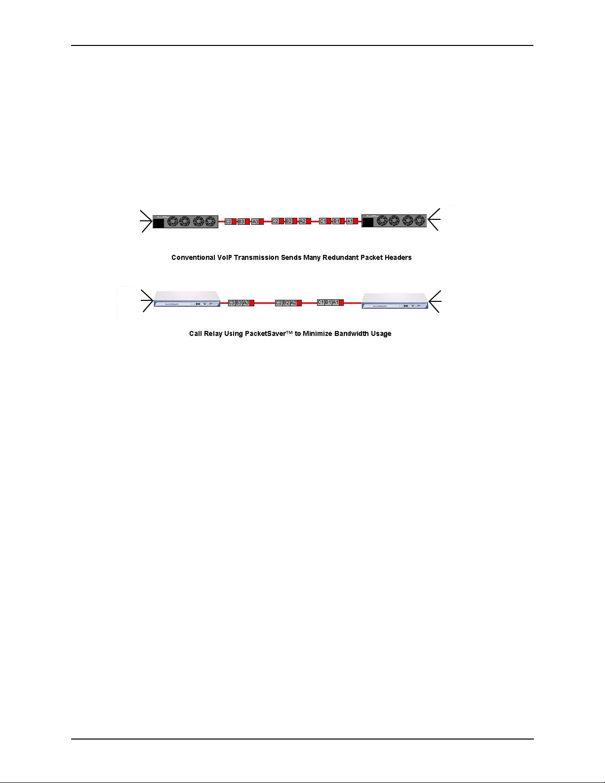
PacketSaver™
PacketSaver packet multiplexing technology reduces the amount of IP bandwidth required to support multiple calls flowing between two networks. PacketSaver minimizes bandwidth usage by
aggregating samples from multiple VoIP conversations and packing them into a larger IP packet
with a single IP header. The process removes the need to send a bulky IP header with individual
voice samples. As a result, it eliminates the transmission of redundant information.
Figure 1-9 PacketSaver
Call A
Call B
Call C
Call A
Call B
Call C
Call Relay 60
Call Relay 60
Call A
Call B
Call C
Call A
Call B
Call C
Call Detail Recording
Through the Call Detail Recording (CDR) feature, the Call Relay 60 is able to generate a CDR at the
completion of each call. A CDR is a string of ASCII data which contains call information such as
call date and time, call length, calling party and called party. From this information you can capture
billing type data, which can be used to create billing reports.
P/N 480-0076-00-00 1-9
Page 18
Chapter 1: Overview
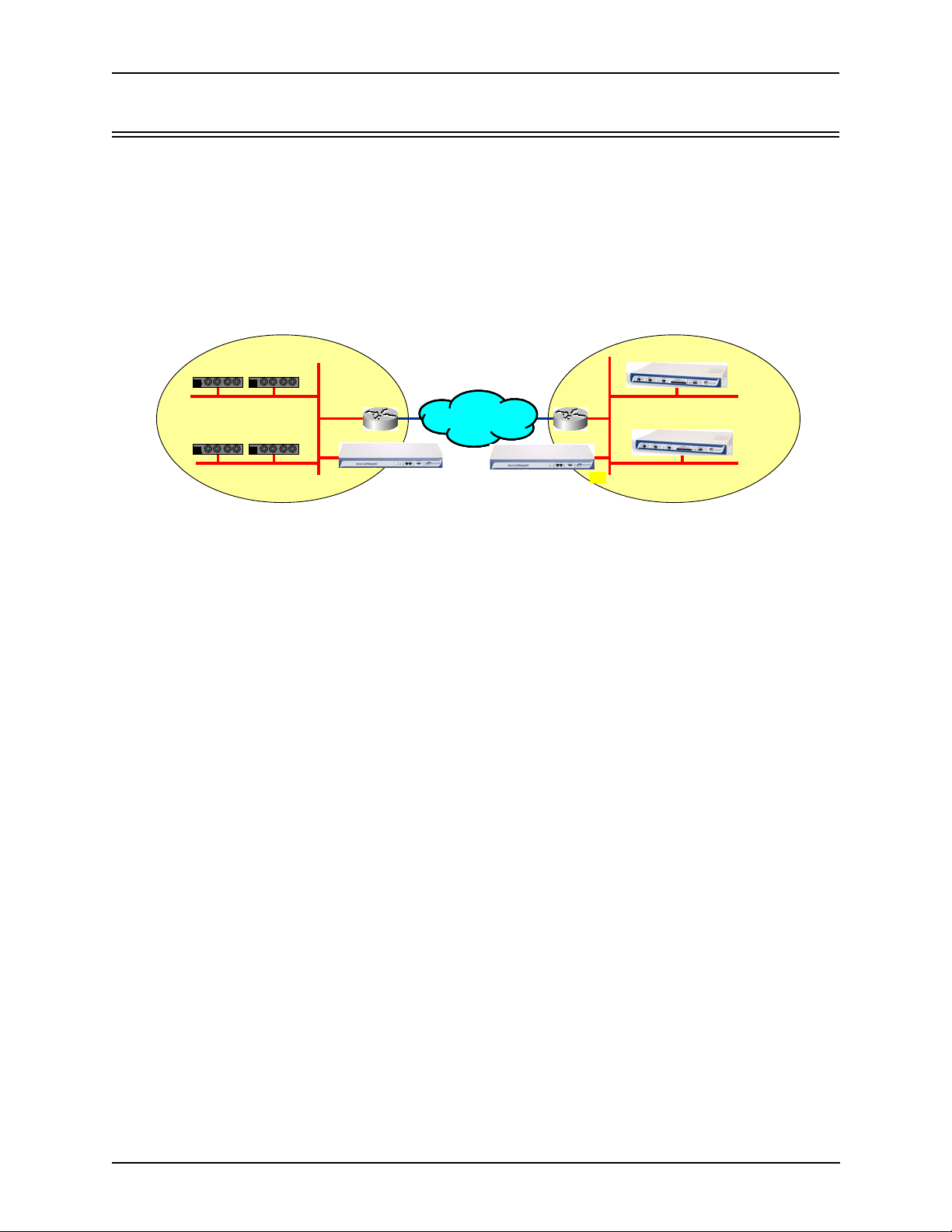
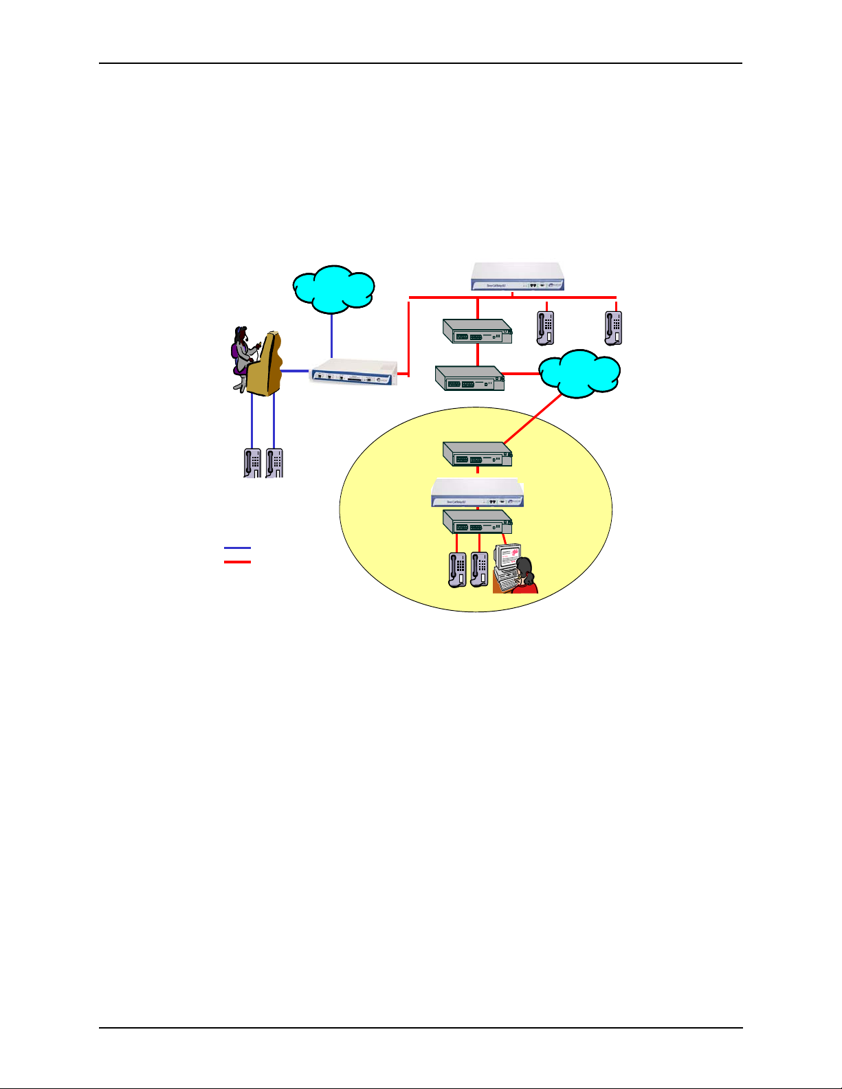
Call Relay 60 with Tenor MultiPath Switch
See Figure 1-10 for an example of using Call Relay 60 with the Tenor VoIP MultiPath Switch. The
Tenor VoIP MultiPath switch will route calls coming from the Call Relay 60 unit, to either the PSTN
or PBX.
PABX
Analog Phones
PSTN
Figure 1-10
PSTN
PSTN
Tenor VoIP Switch
BRANCH OFFI CE
or TELEWORKER
IP
Call Relay 60
Call Relay 60
Swit ch
Router/ NAT/
Fir ewall
Call Relay
Router/NAT/Firewall
Router/NAT/Firewall
IP Phones
Swit ch
PC
Call Relay
IP Phones
IP Network
IP Network
60
P/N 480-0076-00-00 1-10
Page 19

Chapter 2: Hardware Components
This chapter tells you what is contained in your hardware package. A description of each component
is also included.
Specifically, the following topics are covered:
Hardware
Cables
Specifications
P/N 480-0076-00-00 2-1
Page 20
Chapter 2: Hardware Components
Hardware Description
Call Relay 60 is a stackable/rack mountable device which provides connections to two different
sites: Ethernet LAN and a PC.
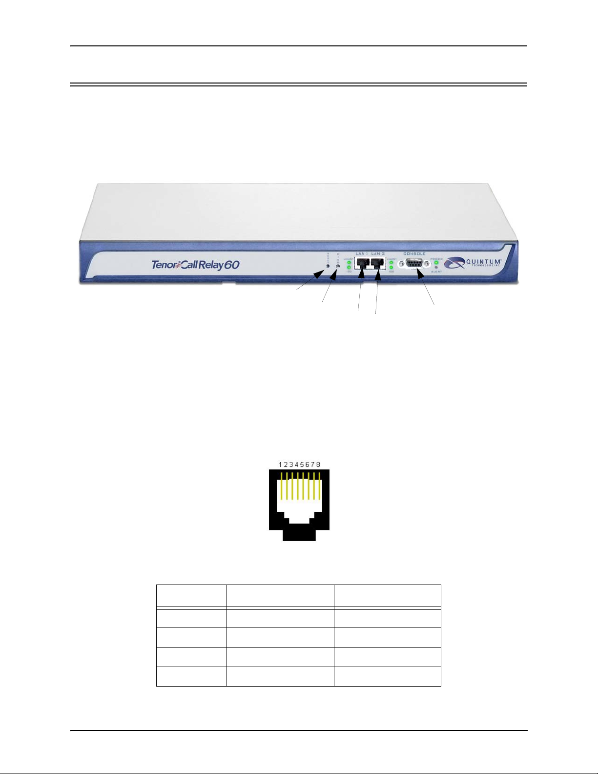
Front Panel Connections and Reset/Diag Options
Figure 2-1 Front
Reset
Diag
View
LAN1/LAN2
Console Port
Reset. Resets the entire unit.
Diag. Enables you to perform software diagnostic procedures.
LAN 1/LAN 2 10/100 Base-T Ethernet ports. LAN 1 port provides an RJ-45 jack for an individual
connection to a 10/100 Ethernet LAN switch or hub via RJ-45 cable; it is individually configured
with a unique IP and MAC address. LAN 2 Ethernet port is reserved for future use.
Figure 2-2 10/100 BASE-T Ethernet Port Pin Order
Table 2-1 Input/Output 10/100 Ethernet port
Pin # Signal Definition
1 TX + Transmit Data
2 TX - Transmit Data
3 RX + Receive Data
4 RSVD Reserved
P/N 480-0076-00-00 2-2
Page 21

Chapter 2: Hardware Components
Pin # Signal Definition
5 RSVD Reserved
6 RX - Receive Data
7 RSVD Reserved
8 RSVD Reserved
• Console port. This RS-232 connector is used for connection to a PC’s serial port via DB-9
serial cable at 38400 BPS 8 N 1, None. The input/output signals are listed in
Table 2-2.
Figure 2-3
DB-9 Female Connector Pin Order
5 4 3 2 1
9 8 7 6
Table 2-2 Serial RS232 DB-9 Connector Pinouts
Pin # Function Description
1 DTR Data Terminal Ready
2 TXD Transmit Data
3 RXD Receive Data
4 CD Carrier Detect
5 GND Signal Ground
6 N.C. No Connect
7 N.C. No Connect
8 N.C. No Connect
9 N.C. No Connect
P/N 480-0076-00-00 2-3
Page 22

Chapter 2: Hardware Components
Front Panel LEDs
The LEDs display the health of the system. There are different types of LEDS: LAN, Alert, and
Power. For LED definitions, see
Tab l e 2- 4.
Figure 2-4 Front Panel LEDs
Power LED
LAN LEDs
Alert LED
Table 2-3 Front Panel LEDs Definitions
LED Label LED Color Description
Link/ACT Green On: Link is good.
Flashing: Line is working properly
and activity is on the line.
LAN1
LAN2 (LAN 2
is reserved for
future use)
Power Power Green On: Indicates power is on.
Alert Alert Amber Operational Status.
100 Green On: Activity is being transmitted at
Off: Link has failed or no cable
attached.
100 Mbps.
Off: Activity is being transmitted at
10 Mbps.
Off: Power is off.
Off: Call Relay 60 is working
properly.
On: One or more diagnostic tests
have failed.
P/N 480-0076-00-00 2-4
Page 23

Back Panel
AC Receptacle
Chapter 2: Hardware Components
Power Switch
Ground Screw
Label
• AC Receptacle. Receptacle in which to plug in a power cord; the other end will plug into an
AC outlet for power.
• Power Switch. Switch to turn power on and off.
• Ground Screw. An additional functional earth ground screw.
• Label. A label that displays UL, model, and power information.
P/N 480-0076-00-00 2-5
Page 24

Chapter 2: Hardware Components
Cables
The cables listed in Tab l e 2- 4 are required to connect a Call Relay 60 to various interfaces. Contact
Quintum for ordering information, if necessary.
Table 2-4 Cables Supported
Cable Usage
RJ-45 Ethernet cable (grey) Connection to Ethernet LAN 10/100.
DB-9 Serial RS-232 (for use with CPU) Connection to PC’s asynchronous console
port.
Detachable (IEC) AC Power Supply Cord (for AC
units only)
Connection to AC power jack.
RJ-45 Ethernet Cable (10/100)
An RJ-45 (10/100 Base-T) straight through cable is used to connect Call Relay 60 to an Ethernet
LAN. Cable pinouts are listed in
Figure 2-6. Color specifications are applicable to the RJ-45 cable
provided.
8
1
Figure 2-5
Figure 2-6
Pin # Connects to Pin #
1
2
3
4
5
6
7
8
RJ-45 (10/100 Base-T) Connector Pinouts
1
RJ-45 Pin Order
Side View
Top View
1
8
2
3
4
5
6
7
8
P/N 480-0076-00-00 2-6
Page 25

Chapter 2: Hardware Components
Table 2-5
Pin # Signal Definition Color
1 TX + Transmit Data White w/orange
2 TX - Transmit Data Orange
3 RX + Receive Data White w/green
4 Unused Unused Blue
5 Unused Unused White w/blue
6 RX - Receive Data Green
7 Unused Unused White w/Brown
8 Unused Unused Brown
RJ-45 (10/100 Base-T) Connector Pinouts
P/N 480-0076-00-00 2-7
Page 26

Chapter 2: Hardware Components
DB-9 Serial RS-232 Cable
The Serial RS-232 9-pin cable DB-9 (male/female) cable is used to connect the Call Relay 60 to
your PC’s RS-232 serial port. The pin order for DB-9 male and female connectors are shown in
ure 2-7 and Figure 2-8.
Fig-
Figure 2-7
DB-9 Male Connector Pin Order
1 2 3 4 5
6 7 8 9
Figure 2-8
DB-9 Female Connector Pin Order
5 4 3 2 1
9 8 7 6
Figure 2-9
Pin # Connects to Pin #
1
2
3
4
5
6
7
8
9
DB-9 Connector Pinouts
1
2
3
4
5
6
7
8
9
Table 2-6 DB-9 Connector Pinouts
Pin # Function Description Pin #
1 DTR Data Terminal Ready 1
2 TXD Transmit Data 2
3 RXD Receive Data 3
4 CD Carrier Detect 4
5 GND Signal Ground 5
6 N.C. No Connect 6
7 N.C. No Connect 7
8 N.C. No Connect 8
9 N.C. No Connect 9
P/N 480-0076-00-00 2-8
Page 27

Chapter 2: Hardware Components
Specifications
Voice/Fax
Coding: A-law, u-law
Voice Algorithms: G.723, G.723.1A (5.3, 6.3 Kbps), G.726 (16, 24, 32, 40 Kbps), G.729,
G. 7 1 1
Fax Support: Group III at 2.4, 4.8, 7.2, 9.6, 12, 14.4 Kbps
LAN Connection
LAN Support: 10/100 Mbps Ethernet
Connection Type: Full Duplex/Half Duplex
Physical
Position: 19” (48.7 cm) rack mountable or wall-mountable
Depth: 10 3/4” (27.6 cm)
Width 17 3/8” (44.5 cm)
Height: 1 3/4 ” (4.5 cm)
Weight 7.2 lbs (3.24 kg)
Electrical
Ethernet: Standard 10/100Base-T RJ-45 interface (IEEE 802.3)
Console Port: RS-232/DB-9 Female
Power 100-240 VAC, 1.0A - 0.5A, 50-60 Hz
Environmental
Operating Temperature: 40° to 104° F (5° to 40° C)
Operating Humidity: 20% to 80% non-condensing
Operating Altitude: -200 to 10,000 feet (-60 to 3,000 meters)
Storage Temperature: 14° to 140° F, (-10 to 60°C)
P/N 480-0076-00-00 2-9
Page 28

Chapter 3: Installation
This chapter gives you installation instructions, as well as how to position the Call Relay 60 successfully within your network.
Specifically, the following topics are covered:
Installation
Connection
Install Ground Cable (if required)
Power up the System
Assign IP Address
Load Software Upgrade
P/N 480-0076-00-00 3-1
Page 29

Chapter 3: Installation
Installation
Before you begin the actual installation, review the pre-installation guidelines which follow and
inspect the package contents.
Pre-Installation Guidelines
• Do not connect equipment in wet conditions and keep the unit away from dusty areas.
• The area must not exceed the temperature and humidity guidelines outlined in Chapter 2:
Hardware Components
• Avoid exposing the unit to excessive vibrations.
• Mechanical loading of rack should be considered so that the rack remain stable and unlikely to
tip over. Ensure no equipment is put on top of the unit.
Inspect Package Contents
Before you install the hardware, ensure the following components are included in your shipment:
• Tenor Call Relay 60 and Mounting Hardware
• 1 AC Power Cable
• DB-9 RS-232 Serial Cable
• RJ-45 LAN Cable
• Product Guide in CD format
If a listed component is not included in your package, contact your customer service representative.
P/N480-0076-00-00 3-2
Page 30

Chapter 3: Installation
Rack Install
Locate the Call Relay 60 unit within the same area as your PBX, Ethernet hub, switch, router, and/or
PSTN patch panel. The chassis is intended to be installed in a 19” rack.
Mounting brackets are attached to the chassis; the rack is not included with your system. Included
with the chassis are the screws listed below. The sizes should allow installation in most racks. If
your rack does not use the same size screws listed in the table, please consult the instructions you
received with the rack.
Required Materials
• 19” rack (not included with system)
• #8 - 32 x 3/8 screws (qty: 2) (included with system)
• screws as required by your rack manufacturer
Install the chassis in a rack as follows:
1. Choose a position for the chassis within the rack.
WARNING: If the Tenor Call Relay 60 unit is the only equipment installed in the rack, ensure it is
level with the rack to avoid the rack from becoming unbalanced. Mount as low as
possible to avoid a high center of gravity.
2. Align the unit’s mounting brackets flush with the rack’s mounting holes (see Figure 3-1) and follow the vendor specific instructions for rack installation. The screws provided require a Phillips
#2 screwdriver.
3. Ensure the chassis is secured firmly to the rack.
P/N 480-0076-00-00 3-3
Page 31

Chapter 3: Installation
Rack
Mounting
Holes
Figure 3-1
Rack Installation (Front View)
Call Relay 60
Wall Mount
There are two mounting brackets available to mount the unit to the wall.
Pre-installation Guidelines
• Ensure the wall is level and stable.
• Do not attach the unit to a temporary wall.
• Ensure the wall mounting area is within cord distance of the power outlet.
Required Materials
• 2 wall mount brackets (including 2 screws)
• Drill
• 3/16 drill bit
• Measuring tape or ruler
•Hammer
• Phillips head screwdriver
P/N480-0076-00-00 3-4
Page 32

Chapter 3: Installation
Attach the unit to the wall as follows:
1. Determine the wall area to mount the unit. With chalk or a soft pencil, mark the install area
according to
NOTE: Ensure the unit is level.
Figure 3-2.
Figure 3-2 Wall Mounting Dimensions
7 3/4” (19.9cm)
3/16”
2. Position and attach one mounting bracket to the unit using a screw existing in the system and one
screw included with the package. See
Figure 3-3.
3. Position and attach the other mounting bracket using a screw existing in the system and the
remaining screw in the package. See
Figure 3-3
Mounting
Brackets
Unit front
Figure 3-3.
Wall Mount Installation
Attach each bracket to the
unit using 1 screw already installed
in the unit (unscrew and re-insert)
and 1 screw already included
with the package.
Note: Ensure unit is level.
4. Mount the unit to the wall using the four remaining screws included with the system.
5. Ensure the unit is firmly mounted against the wall.
P/N 480-0076-00-00 3-5
Page 33

Chapter 3: Installation
Connection
Connect to Ethernet LAN
You can use these instructions for general connection purposes only. The Ethernet hub/switch manufacturer’s documentation should provide specific instructions for connection to another device, such
as the Call Relay 60. Only LAN 1 is available for use; LAN 2 is reserved for future use.
Figure 3-4
Connect to Ethernet Hub/Switch
Data
Network
Ethernet Hub/Switch
1. Plug one end of the grey or white RJ-45 Ethernet cable into the port labeled LAN 1.
2. Plug the other end of the cable into one of the Ethernet hub/switch ports. If a custom cable or
adapter is required, see
Chapter 2: Hardware Components for Ethernet RJ-45 10/100.
P/N480-0076-00-00 3-6
Page 34

Chapter 3: Installation
Connect to PC Console
You will need to connect the Tenor Call Relay 60 to your workstation’s serial port via RS-232 con-
nection. (This connection will be used when you assign an IP address to the unit.) For the instructions below, it is assumed you are connecting to a Windows PC.
Figure 3-5
Connect to PC Com Port
DB-9
1. Insert the male end of the DB-9 cable into the port labeled Console. (See Chapter 2: Hardware
Components for RS-232 connector pinouts.)
2. Insert the female end of the DB-9 cable into your workstation’s serial port (see your PC documentation for more information about this port).
P/N 480-0076-00-00 3-7
Page 35

Chapter 3: Installation
Install Ground Cable (if required)
The Call Relay 60 provides an Earth Ground point by way of a #6 screw at the rear panel. This
screw provides an additional functional Earth point, if required in your installation. Safety ground is
provided through the third wire of the AC power cord provided with your unit. For continued safe
operation, a three wire AC power cord must be used; failure to do so will void the warranty and
Agency approvals.
Connect the Ground Cable as follows:
1. Unscrew the existing screw from the grounding hole.
2. Place the screw through the connector of the ground cable.
3. Attach the screw securely to the threaded grounding hole.
4. Connect the other end of the ground cable to an approved electrically grounded object. Consult
with a licensed electrician if you are unclear about this operation.
Figure 3-6
Install Ground Cable
P/N480-0076-00-00 3-8
Page 36

Chapter 3: Installation
Power up the System
Once you have all cables connected properly, you are ready to turn the system on as follows:
1. Plug in the power cord to an AC outlet.
2. Locate the on/off switch on the back of the unit and click the switch to On.
The unit will power up and the LEDs will flash and turn off; the power LED will remain lit. For
information about the LEDs, see
Once the unit is powered up, you are ready to assign an IP address. See the following section Assign
IP Address.
Chapter 2: Hardware Components.
P/N 480-0076-00-00 3-9
Page 37

Chapter 3: Installation
Assign IP Address
Before you can configure Call Relay 60, you need to assign a valid IP address. An IP address is a 32
bit (up to 12 numeric characters) address used to identify each network device in the TCP/IP net
work.
Assign IP address as follows:
1. Click on Start> Programs> Accessories> Communications> HyperTerminal> Run. The Hyper-
Ter mi na l window will be displayed.
2. Click on Hyperterm.
3. Enter a Connection Description (i.e., name for each unit such as CR60 NJ).
4. Click Ok.
5. Choose the connection port on your PC from the Connect Using drop down list box (i.e., Direct
to Com 1). Click Ok. The Com1 Properties window will be displayed. See
Figure 3-7.
-
Figure 3-7 Port Settings Window
6. From the Bits Per Second drop down list box, choose 38400.
7. From the Data Bits drop down list box, choose 8.
8. From the Parity drop down list box, choose None.
9. From the Stop bits drop down list box, choose 1.
10.From the Flow control drop down list box, choose None.
11.Click on Ok.
P/N480-0076-00-00 3-10
Page 38

Chapter 3: Installation
12.Click on Call>Call. A connection to the Call Relay 60 will be established.
13.After the bootup sequence, the login prompt will appear.
14.Enter a login name. The default login name is admin.
15.Enter a password. The default password is admin. To change this password later, see Chapter 4:
Getting Started with Configuration. Questions about the unit will scroll on the screen.
16.You will be asked to configure an Ethernet port. Enter Y to configure the Ethernet port.
NOTE: If you are unsure of the following values, contact your network administrator.
17.For IP address, enter the IP address for the Call Relay 60 unit.
18.For Subnet Mask prompt, enter the subnet mask. This address is used to differentiate the network
portion of the IP address from the host portion of the IP address.
19.For Default Gateway IP, choose whether there should be a default gateway (router) which routes
packet data outside of your LAN, and enter its IP address.
The Call Relay 60 will automatically reboot with the new IP address.
Load Software Upgrade
To upgrade the software, download the upgrade from the CD ROM you received with the unit, or
download the latest software/documentation from
www.quintum.com.
P/N 480-0076-00-00 3-11
Page 39

Chapter 4: Getting Started with
Configuration
This chapter tells you how to get started configuring and monitoring the Call Relay 60, including the
following: Topics include:
Getting Started with Configuration/Monitoring
Tenor Configuration Manager
Tenor Monitor
Command Line Interface
P/N 480-0076-00-00 4-1
Page 40

Chapter 4: Getting Started with Configuration
Getting Started with Configuration/Monitoring
There are different ways to configure and monitor the Call Relay 60.
• Tenor Configuration Manager. A user-friendly windows-based stand-alone GUI which enables
you to configure a number of Quintum products, including the Call Relay 60. This software
was designed to run on any PC; you simply designate the IP address for the Call Relay 60.
• Tenor Monitor. A user-friendly windows-based stand-alone GUI which enables you to monitor
the Alarms, Call Detail Records (CDRs) and perform call monitoring functions for the Call
Relay 60.
• Command Line Interface (CLI). Enables you to configure the Call Relay 60 through a CLI tel-
net-based session.
Basic information is included in this section; for complete information, including all field definitions and extensive usage instructions, see the Tenor Configuration Manager/Tenor Monitor User
Guide and the Command Line Interface User Guide (or the Online Help available with the soft
ware). Along with the CD you received with the unit, you can also access the latest software and
upgrade information from
www.quintum.com.
-
Tenor Configuration Manager
The Tenor Configuration Manager is used to configure all aspects of the Call Relay 60, including
system, Ethernet, CDR, signaling, circuit, and VoIP configuration. Through the Configuration Man
ager, you are able to configure all aspects of the Tenor unit. The manager is a user-friendly GUI
which enables you to configure Quintum products; you designate the IP address of the Tenor prod
-
uct you want to configure.
Get started with the Configuration Manager as follows:
NOTE: Ensure the software is installed and running.
1. Access the Tenor Configuration Manager icon (located in the area in which you specified during
installation). For example, click on Start > Programs >Quintum Tenor Configuration Manager>
Tenor Config Manager. The Tenor Configuration Manager will launch. The Specify Tenor IP
Address window will be displayed.
2. From the Tenor IP Address drop down box, click on Specify New IP Address (if the IP address is
already listed from a previous login, select that IP address and you will automatically be con
-
nected).
3. Enter the IP address of the Tenor unit in which you would like to configure.
-
4. Enter the Tenor Server Port (the value must match the port numbers set through the CLI; the
default entry is 8080).
5. Click Ok. The Confirm Login and Password screen will be displayed.
P/N 480-0076-00-00 4-2
Page 41

Chapter 4: Getting Started with Configuration
6. Enter a user name and password (the default user name is admin; the default password is
admin). Click ok. You are now ready to configure the Tenor unit.
Once you have connected to the Configuration Manager, you can move around and configure data.
For complete information about the field definitions, valid entries, and submit information, see the
Tenor Configuration Manager/Tenor Monitor User Guide or the online help system that came with
the system.
Tenor Monitor
The Tenor Monitor enables you to view alarms for all Tenor units, as well as Call Event Records,
and Call Detail Records. There are three main functions of the Tenor Monitor:
• Alarm Monitor. Through the Alarm Monitor, you are able to view alarms for a specified IP
address, as well as display active alarms, alarm history, and deleted alarms. You can configure a
database table for the specific unit in which you would like to monitor alarms.
• Call Monitor. Through the Call Monitor, you are able to view call events for each call passing
through the Tenor, including call type, duration, call state, etc. The Call Monitor continuously
collects active, real-time call event data and displays it on the screen. You are able to select/
edit/delete a Tenor to a database table for the specific unit in which you would like to view call
events.
• Call Detail Record (CDR) Monitor. Through the CDR Monitor, you are able to view the Call
Detail Record for each call, including the call connect/disconnect times, call path, and
autoswitch information.
Through the Tenor Monitor, you can view real-time data for up to three Tenors at the same time. The
Tenor Monitor can collect up to 500,000 CDR/Call Event Records per day.
View call monitoring information as follows:
NOTE: Ensure the software is installed and running.
1. Access the Tenor Monitor icon (located in the area in which you specified during installation. For
example, click on Start > Programs >Quintum Tenor Monitor>Tenor Monitor. The Tenor Moni
tor will open up. The User Name and Password window will be displayed.
2. Enter a user name and password (the default user name is admin; the default password is
admin). Click OK.
You are now ready to monitor a specific Tenor unit. See the Tenor Configuration Manager/Tenor
Monitor User Guide for specific information about adding an IP address, moving around the Teno r
Monitor, using screens, and switching between IP addresses to view alarms, CDR, and call informa
tion.
-
-
Command Line Interface
The Command Line Interface (CLI) is a Telnet-based (also accessible via serial port) list of menu
options which enable you to configure and monitor any Call Relay 60 unit; you can configure fea
tures and capabilities such as numbering plans, channel usage, border element, signaling type, and
P/N 480-0076-00-00 4-3
-
Page 42

Chapter 4: Getting Started with Configuration
routing information. In addition, you are also able to monitor system alarms and run diagnostic procedures. CLI attributes enable you to further configure CLI options; these provide additional configuration items according to the option type.
Through the CLI, there are also commands you execute to simplify the process of configuring and
monitoring the Call Relay 60 unit. Some of these commands are globally used, others are specific to
the mode in which you are working. For example, the set command, available globally from within
the Configuration mode, enables you to set attributes for different options.
You can access the CLI through a Telnet session, a terminal-like access to any Call Relay 60 unit. If
your PC is directly connected to the Call Relay 60 unit, you can configure the unit directly through
the serial port using HyperTerminal. Both methods are described below.
NOTE: Alternatively, you may want to use other telnet clients, such as the Linux telnet client or
free programs like Putty. If you choose to do so, you may have to make minor setting
changes in the Telnet client in order to make it function properly.
Telnet Connection. Once the Call Relay 60 has been initially configured with an IP address net-
work and is connected, the easiest way to connect to the unit and use the CLI is through a standard
Telnet session from any PC on your IP network. Connect to a Call Relay 60 unit via Telnet as fol
-
lows:
For Windows 95/Windows 98:
1. Click on Start> Run. The Run dialog box will be displayed.
2. Type telnet and click on Ok.
3. Click on Connect> Remote System.
4. In the Host Name field type, enter the IP address assigned to your Call Relay 60.
5. Click on Connect.
A connection to the Call Relay 60 unit will be established.
For Windows 2000 and above:
1. Click on Start> Run.
2. The Run dialog box will be displayed. Type telnet and click on Ok. (Or type telnet followed by
the IP address and you will connect.)
3. At the telnet prompt, type open (followed by the IP address for the unit to which you want to
connect.)
A connection to the Call Relay 60 unit will be established.
Serial Port Connection. When the Call Relay 60 is first shipped to you, you must connect to the
unit using this method to assign an IP address. Once this is assigned, you can use the CLI to reach
P/N 480-0076-00-00 4-4
Page 43

Chapter 4: Getting Started with Configuration
the serial port of the Tenor. A null-modem cable must be used to connect to the CLI using this port,
if you are directly connected to the unit. To connect to the Call Relay 60 serial port, locate a work
-
station (PC) close to the unit. Connect as follows:
1. Insert one end of the DB-9 serial null modem cable into the Call Relay 60’s serial port.
2. Insert the other end of the DB-9 serial cable into your workstation’s Com/serial port.
Once the cable is connected and the Call Relay 60 is powered on, open a HyperTerminal session (or
other terminal emulation program) as follows:
3. Click Start > Programs > Accessories > Communications > HyperTerminal. The HyperTermi-
nal window will be displayed.
4. Click on Hypertrm.
5. Enter a connection description (i.e., name for each unit such as Call Relay 60 1).
6. Click Ok.
7. Choose a connection port (on your PC) from the Connect Using drop down list box (i.e., Direct
to Com 1). Click Ok. The Com 1 properties window will be displayed.
8. From the Bit Per Second drop down list box, choose 38400.
9. From the Data Bits drop down list box, choose 8.
10.From the Parity drop down list box, choose None.
11. From the Stop bits drop down list box, choose 1.
12.From the Flow Control drop down list box, choose None.
13.Click on Call>Call. A connection to the Call Relay 60 will be established.
14.Enter a login name. The default logon name is admin.
15.Enter a password. The default password is admin. Questions about the unit will scroll on the
screen.
NOTE: Steps 16-18 are used for the first time assignment of an IP address.
16.For IP address, enter the IP address for the Call Relay 60 unit.
17.For Subnet Mask for LAN prompt, enter the subnet mask. This address is used to differentiate the
network portion of the IP address from the host portion of the IP address.
18.For Default Gateway prompt, enter the IP address for the default gateway (router) which routes
packet data outside of your LAN.
P/N 480-0076-00-00 4-5
Page 44

Chapter 4: Getting Started with Configuration
The Call Relay 60 will reboot automatically.
Once you are connected to the Command Line Interface, you can configure the system, as well as
perform diagnostics and monitor system information. For specific information, see the Online Help
you received with the CD.
P/N 480-0076-00-00 4-6
Page 45

Chapter 5: System Alarms
This chapter tells you how to use the Alarm Manager to view and understand alarms generated by
the system. Specifically, the following topics are included:
Monitor Alarms
View Alarms
P/N 480-0076-00-00 5-1
Page 46

Chapter 5: System Alarms
Monitor Alarms
Alarms are brief text messages that appear on your workstation when the Call Relay 60 unit encounters a problem, such as a failed interface, disconnected call, etc. You can reach the Alarm Manager
via Command Line Interface (CLI) alarm monitoring system.
How to Read Alarms
The Alarm Manager reports alarms according to criteria such as the alarm’s severity level, type,
description, etc. There are two alarm types displayed: Active Alarms and Alarm History. An Active
Alarm list displays all the alarms still active on the system; these alarms have not been cleared or
deleted. An Alarm History is a list of the last 100 alarms stored in the system since the last time you
performed a delete operation.
Definitions for all generated alarm fields appear in Table 5-1.
Table 5-1 Alarm Fields and Definitions
Field Definition Valid E n try
IP # The unit’s IP address (32 bit
address).
Sequence # Internal number used to identify
alarms.
Type (displays only if you generate an Alarm History)
Severity Level or alarm severity. 1 = Critical (complete system is
The type of alarm generated. ALR = Alarm. This indicates an
Example:192.168.1.34.
01, 02, 03, etc.
active alarm.
CLR= Clear. This indicates an
alarm that has been cleared from
the system.
RPT= Report. This indicates that
the alarm has been generated for
a report. This entry is for internal
use only; if you see a report that
is causing problems, contact cus
tomer service.
affected).
2 = Major (major problem is
detected).
3 = Minor (minor problem is
detected).
4 = Info (Information about a
minor problem).
-
Description A text description of the alarm;
see
Table 5-2 for detailed descrip-
tion.
P/N 480-0076-00-00 5-2
Va ri es .
Page 47

Chapter 5: System Alarms
Field Definition Valid Entry
Slot # Defines which slot the alarm
occurred on.
Device # Defines which device in a slot the
alarm occurred on.
Line # Specifies which line the alarm
occurred on.
Channel # Specifies which channel the alarm
occurred on.
Date/Time Date/time the event occurred on. Day of week: name of day.
N/A
N/A
N/A
N/A
Month: Jan, Feb, March, etc.
Day of month: 1 or 2 digits.
Time: 6 digits (hour minutes seconds based on a 24-hour clock).
Year: 4 digits.
P/N 480-0076-00-00 5-3
Page 48

Chapter 5: System Alarms
Valid Alarms
The following is a list of all alarm descriptions (text that appears in the Alarm Description field) for
all possible alarms the system can generate. In the generated alarm list, the alarm description
appears as part of the Description field.
Table 5-2 List of Valid Alarms
Severity
(appears as
part of severity
field)
Critical Ethernet Disconnected Ethernet cable has been disconnected or Ethernet con-
Alarm Description
(text appears in desc field)
Definition
nectivity has been lost.
Critical Call Handler not registered with Gate-
keeper
Critical Critical Software Error A software error has occurred that affects the operability
Critical Call Relay 60 reset The unit has reset.
Critical Operational Code Missing Normal application code CPU is damaged.
Critical Configuration Data Missing Configuration via CLI is missing. Check the configura-
Critical Power Degrade Power supply is not working correctly.
Critical RADIUS Configuration Missing Appears when a RADIUS request is made and one or
Critical RADIUS Server Not Responding Appears when none of the configured RADIUS servers
The Call Handler process cannot be registered with the
Gatekeeper.
of the complete system.
tion data and add the necessary information.
more required configuration parameters are missing.
This alarm is cleared when the required RADIUS
parameters are configured via CLI.
respond.
This alarm is cleared when any of the RADIUS servers
responds or the RADIUS server is disabled via CLI.
Major Major Software Error A software error has occurred that affects system signal-
ing, interfaces, or other major operation.
Major File Missing in the File Server This alarm will be reported to the system when a partic-
ular voice prompt file is not found in the IVR Prompt
Server.
This alarm applies only to the system with enabled IVR
functionality.
P/N 480-0076-00-00 5-4
Page 49

Chapter 5: System Alarms
Severity
(appears as
part of severity
field)
Major Switch to other RADIUS server Appears when the current RADIUS server stops
Minor Call Event(s) Lost A call has failed.
Minor Missing or Incorrect Profile The configuration profile has caused a problem.
Minor Minor Software Error A software error has occurred but will not affect the
Minor Call Relay 60 resource constrained A shared resource in the unit loads the system.
Minor Hardware component failed A hardware component has failed. Check all compo-
Minor Log RADIUS server error Displayed when the RADIUS server fails to send
Alarm Description
(text appears in desc field)
Definition
responding after three consecutive calls end in timeouts
and another RADIUS server is configured. The Tenor
will then switch to the next RADIUS server.
operation of the complete system.
nents, hardware connections, etc.
required data or the data sent by the RADIUS server has
improper values. Incorrect information may contain the
following:
RADIUS Server: Credit amount (-1)
RADIUS Server: Credit minus amount
RADIUS Server: Not supported currency
RADIUS Server: Credit time (-1)
RADIUS Server: Credit time < 6 sec
RADIUS Server: Invalid error code
Informational Gatekeeper status Reports the status of the Gatekeeper.
Informational Miscellaneous information Miscellaneous information about the unit is reported.
The contents of this alarm will vary.
Informational Info Software Error Indicates information about miscellaneous software
error. This does not affect system operation.
P/N 480-0076-00-00 5-5
Page 50

Chapter 5: System Alarms
View Alarms
The Command Line Interface (CLI) enables you to view alarms through the Monitor mode. You can
view active alarms, as well as view an alarm history list.
Display all Alarms
You are able to display both active alarms and an alarm history as follows:
1. Through CLI, access the Monitor prompt.
2. Type alarm. Both active alarms and the alarm history will be displayed. See section How to Read
Alarms for field definitions.
Figure 5-1 Alarm sample
IP# Sequence# Type Severity Desc Slot# Device# Line# Channel# Date/Time
192.168.20.444:4:ALR:1:Call Handler not Registered with Gatekeeper:0:0:0:0:THU JAN 13 13:21:27 2005
192.168.20.444:5:RPT:4:Gatekeeper status (Gatekeeper(0.0.0.0) register):0:0:0:0:THU JAN 13 13:21:27
2005
Display Active Alarms
1. Through CLI, access the Monitor prompt.
2. Type alarm a. The active alarms will be listed. See section How to Read Alarms for field defini-
tions. If you enter alarm without a command following it, both active alarms and the alarm history will be displayed.
Figure 5-2
Active Alarm Sample
IP# Sequence# Type Severity Desc Slot# Device# Line# Channel# Date/Time
192.168.20.444:10:CLR:3:Border Element connection lost:0:0:0:0:THU JAN 13 13:21:27 2005
P/N 480-0076-00-00 5-6
Page 51

Chapter 5: System Alarms
Display Alarm History
1. Through CLI, access the Monitor prompt.
2. Type alarm h. An alarm history will be displayed. See section How to Read Alarms for field def-
initions. If you enter alarm without a command following it, both active alarms and the alarm
history will be displayed.
Figure 5-3
Alarm History Sample
IP# Sequence# Type Severity Desc Slot# Device# Line# Channel# Date/Time
192.168.20.444:4:ALR:1:Call Handler not Registered with Gatekeeper:0:0:0:0:THU JAN 13 13:21:27
2005
P/N 480-0076-00-00 5-7
Page 52

Chapter 6: Diagnostics/Maintenance
This chapter tells you how to troubleshoot Call Relay 60 operation, as well as how to maintain the
health of your system. You will find information about how to monitor LEDs, as well as how to per
form general maintenance.
Specifically, the following topics are included:
Before you Begin
Monitor LEDs
Diagnostics
Monitor Alarms
General Maintenance
If you need Additional Help
-
P/N 480-0076-00-00 6-1
Page 53

Chapter 6: Diagnostics/Maintenance
Before you Begin
Before you begin troubleshooting a potential malfunction, it is a good idea to check your basic hardware connections. See below.
• Ensure power cord is firmly installed in the back panel’s power jack and the other end is
plugged into the AC power source.
• Ensure the unit’s power switch is in the On position. If the unit is not working, toggle the power
switch to reset the system. If the unit is reset, the settings you configured may be lost.
• Verify that all RJ-45 and DB-9 cables fit snugly in each front panel jack. Faulty connections
may cause a number of network interfacing or connection issues.
If you suspect the problem to be on the network end, contact your Central Office to verify proper
operation.
Monitor LEDs
LEDs monitor the health of the system; they are the first signal that the unit is not working properly
or that an internal or external error has occurred. LEDs appear on the front of the unit (LED descrip
tions are detailed in Chapter 2: Hardware Components).
Check Chapter 2: Hardware Components to ensure the correct lighting of each LED and then see
Common Symptoms/Problems for troubleshooting information. If the LEDs are not lighting at all,
check the AC power source to ensure power is being supplied to the unit.
-
P/N 480-0076-00-00 6-2
Page 54

Chapter 6: Diagnostics/Maintenance
Diagnostics
Common Symptoms/Problems
Below is a list of common symptoms and problems you may encounter. Use this list as a guideline;
if your problem is not listed, use the diagnostic procedure explained in the beginning of this chapter.
Table 6-1 Common Symptoms/Problems
Common Symptom/Problem Description/Solution
Unit will not turn on. Check AC power source.
Communication with Command Line Inter-
face (CLI) cannot be established using Telnet.
The IP address of the Call Relay 60 unit may be incorrect.
Check Ethernet Cable.
Verify the IP address of Call Relay 60. Check the Default
Gateway Subnet Mask. Check Ethernet connection via RS232 connection. See
Verify network connectivity using ping from another network host. See Chapter 4: Getting Started with Config-
Chapter 3: Installation.
uration.
ALERT LED is on and not flashing. One or more internal diagnostic tests have failed. Contact
customer service. LED will stay on for a minute or so when
the unit is powered up.
Communication with Ethernet Hub, or
switch cannot be established.
Communication between the PC’s COM
port and Call Relay 60 serial port cannot be
established.
Verify RJ-45 cable is firmly installed in the Ethernet port.
Check MDI/MDIX configuration. Check duplex setting on
the switch in which they were connected and the speed of
10MB or 100 MB.
Verify DB-9 cable is firmly placed in the unit’s console port
and your PC’s serial port.
Verify Terminal port settings at 38400, 8, N, 1, None
Verify Unit Provisioning
An error with Call Relay 60’s provisioning may cause a number of problems. It may be a simple
error, such as an incorrect IP address, or it may be something more complex, such as incorrect ether
net port configuration.
Evaluate your system provisioning. Re-configure if necessary. See Chapter 4: Getting Started with
Configuration.
P/N 480-0076-00-00 6-3
-
Page 55

Chapter 6: Diagnostics/Maintenance
Ping Unit
Ping enables you to ping an IP address. See Chapter 4: Getting Started with Configuration for more
information.
Monitor Alarms
Alarms
Alarms help you identify where a specific problem is occurring with the Call Relay 60 unit. Through
the CLI, you can review alarms via Command Line Interface (CLI). Verify all severity 1 alarms
first; these alarms indicate that the unit is in critical condition and the entire system is affected.
See Chapter 5: System Alarms for specific information about obtaining and reading alarms.
General Maintenance
Restore Factory Defaults
You can set all system configuration settings back to their factory defaults via Command Line Interface (CLI) as follows:
1. Access the CLI through a Telnet session. See Chapter 4: Getting Started with Configuration for
more information.
2. Access the config# prompt.
3. Type setfactory. You will be asked if you are sure you want to set the unit back to factory
defaults.
4. Type yes to confirm (type no to cancel the restore).
Reset System
1. Access the CLI through a Telnet session. See Chapter 4: Getting Started with Configuration for
more information.
2. Access the Maintain-MasterChassis-1# prompt.
3. Type reset. The unit will be reset.
Change Password
For security purposes, you may want to change your password. You can change the password via
Command Line Interface (CLI) as follows:
1. Access the CLI through a Telnet session. See Chapter 4: Getting Started with Configuration for
more information.
P/N 480-0076-00-00 6-4
Page 56

Chapter 6: Diagnostics/Maintenance
2. Access the maintain# module.
3. Type password. A prompt will ask you for the old password.
4. Type the old password and press Enter. A prompt will ask you for the new password. Type the
new password and press Enter. A confirmation will ask you to confirm the new password.
5. Re-type the new password and press Enter.
A message will tell you the password was changed successfully.
Change Unit Date and Time
You can change the unit’s date and time via Command Line Interface (CLI) as follows:
1. Access the CLI through a Telnet session. See Chapter 4: Getting Started with Configuration for
more information.
2. Access the Config module.
3. Type date followed by mm/dd/yy/hh:mm:ss and press Enter.
4. For example, type config# date 06/14/02/22:14:00. This command will set the current time to
June 14, 2004 at 10:14 p.m.
If you need Additional Help
If you suspect the problem to be on the network end, contact your Central Office to verify proper
operation.
After completing all troubleshooting/maintenance procedures and reviewing the Common Symptoms/Problems section, you can contact the Customer Service Department at the following:
Quintum Technologies, Inc.
71 James Way
Eatontown, NJ 07724
For domestic calls: (877) 435-7553
For international calls: (732) 460-9399
email: service@quintum.com
P/N 480-0076-00-00 6-5
Page 57

GLOSSARY
G
Gatekeeper.An H.323 system which provides call con-
trol and administrative services in H.323 endpoints.
A
Alarm. A brief message that appears on your worksta-
tion when the Call Relay 60 unit encounters a prob-
lem (i.e., failed interface).
Alarm Manager. Reports alarms according to criteria
such as IP address, alarm’s severity level, date/time,
etc. It is accessible via Telnet session.
B
Bandwidth Management. Controls the amount of band-
width available to use for VoIP calls.
Border Element. Provides access into or out of an admin-
istrative domain. The Tenor unit has two types of
Border Elements: Primary and Secondary.
C
Call Relay. A stand-alone unit which acts as an inter-do-
main VoIP portal used to directly connect (over IP)
one or more VoIP networks, supporting up to 64 si
multaneous calls between networks.
CDR. Call Detail Recording. A string of data which con-
tains call information such as call date and time, call
length, calling party and called party.
CDR Server. The server (or workstation) responsible for
receiving and processing CDRs as they are generat
ed.
CLI. Command Line Interface. A Telnet-based (also ac-
cessible via serial port) management system which
enables you to configure and monitor any Tenor Call
Relay unit. For specific information about CLI com
mands, see the CLI user guide you received on the
Quintum CD ROM.
D
DB-9. A standarized connector with 9-pins used to con-
nect the Tenor unit to a PC’s RS-232 console port.
E
Ethernet. A very common method of networking com-
puters in a LAN. The Tenor has a 10/100 Base-T ethernet port.
Extranet. Communications with a source outside your
company.
Gateway. A device (i.e., Tenor VoIP MultiPath Switch)
which connects IP packet-based networks and cir
cuit-switched networks.
H
H.323. A protocol standard for sending multimedia com-
munications (i.e., voice/data) simultaneously over
packet-based networks, such as IP.
I
Internet. A packet based network which transports voice/
video/data over TCP/IP.
Intranet communication. Communication within the
same company, usually through an Ethernet Hub.
IP Address. A unique 32 bit address that identifies a net-
work device is connected to the network via TCP/IP.
L
LAN. Local Area Network. A data communications ar-
rangement which links computers together at the site
to share files, printer, etc., using a local network de
sign, typically Ethernet.
LED.Displays the health of the unit via individual lights
that appear on the front panel. LEDs appear on the
-
front of the unit.
N
NATAccess. Enables VoIP networks with multiple
H.323 endpoints to operate behind firewalls
equipped with Network Address Translation (NAT).
-
P
PacketSaver. A feature which reduces the amount of IP
bandwidth required to support multiple calls flowing
between two networks.
S
SNMP. Simple Network Management Protocol (SNMP)
is the standard protocol used to exchange network in
formation between different types of networks.
Subnet Mask. An IP address that determines how an IP
address is divided into network and host portions ac
cording to the bits.
-
-
-
-
P/N 480-0076-00-00 Glossary-1
Page 58

W
WAN. Wide Area Network. A few remote LAN sites
linked together via modem.
P/N 480-0076-00-00 Glossary-2
Page 59

Warranty/Approvals
QUINTUM TECHNOLOGIES, INC.
LIMITED WARRANTY AGREEMENT
Quintum Limited Warranty
QUINTUM WARRANTY: Quintum warrants that under normal use and conditions (i) the Quintum hardware products covered by this warranty,
for a period of two years, and (ii) all software media, also for a period of two years, will be free from significant defects in materials and workman
ship from the date of purchase from Quintum or Quintum’s authorized reseller or distributor (the “Warranty Period”).
SERVICES:
In the event that you believe that you have discovered any such defect during one of the Warranty Periods listed above, you must call the Technical
Assistance Center (TAC) at 877-435-7553 within the United States or 732-460-9399 Internationally, 9:00 AM to 5:30 PM, Eastern Standard Time,
for initial problem diagnosis. Quintum Technologies will perform warranty service at Quintum Technologies designated facility, provided the cus
tomer returns the Quintum Technologies Product in accordance with Quintum Technologies' shipping instructions. Quintum Technologies' sole
responsibility under this warranty shall be, at Quintum Technologies' option, to either repair or replace the Quintum Technologies Product within 10
days. All defective Quintum Technologies Products, or defective components thereof, returned under this warranty shall become Quintum Technol
ogies' property. If Quintum Technologies determines that the original Quintum Technologies Product did not contain a Material Defect, Purchaser
shall pay Quintum Technologies all costs of handling, transportation, and repairs at Quintum Technologies' prevailing rates, including all costs of
providing an interim Quintum Technologies Product.
The customer will also be given shipping instructions and a Return Material Authorization (RMA) number. This number is to be prominently displayed on the shipping container and referenced on all correspondence pertaining to the returned product. Customers are responsible for shipping
and insurance charges to return the defective product. Quintum shall pay for shipping and insurance charges for the part being sent to the customer.
-
-
-
Please return any hardware together with the accompanying software media to Quintum following the RMA Procedure set out below (you may also
be asked to provide written documentation of your purchase).
CUSTOMER REMEDIES: Quintum and its suppliers’ entire liability and your exclusive remedy shall be, at Quintum’s option (i) repair or replacement of the software media or hardware that does not meet Quintum’s Limited Warranty with new or like-new software media or hardware or (ii)
return of the price paid for software media or hardware that does not meet Quintum’s Limited Warranty. Quintum shall have no responsibility, war
ranty or other obligations whatsoever as a result of (i) the use of the hardware and/or software in a manner inconsistent with the accompanying
manuals, license and limited warranty terms or this Agreement, or (ii) any modifications made to the hardware or software, or (iii) failure of the
hardware or software as a result of accident, abuse or misapplication or (iv) any act of God such as, but not limited to, floods, earthquakes, lighting
or (v) acts of terrorism or war, declared or not.
NO OTHER WARRANTIES: THE WARRANTIES SET FORTH ABOVE ARE EXCLUSIVE AND IN LIEU OF ALL OTHER WARRANTIES.
QUINTUM MAKES NO OTHER WARRANTIES, EXPRESS OR IMPLIED, AND QUINTUM EXPRESSLY DISCLAIMS ALL OTHER WAR
RANTIES, INCLUDING, BUT NOT LIMITED TO, IMPLIED WARRANTIES OF MERCHANTABILITY AND FITNESS FOR A PARTICULAR PURPOSE. MOREOVER, THE PROVISIONS SET FORTH ABOVE STATE QUINTUM’S ENTIRE RESPONSIBILITY AND YOUR
SOLE AND EXCLUSIVE REMEDY WITH RESPECT TO ANY BREACH OF ANY WARRANTY.
LIMITATION ON LIABILITY: NO LIABILITY FOR CONSEQUENTIAL DAMAGES: UNDER NO CIRCUMSTANCES AND UNDER NO
THEORY OF LIABILITY SHALL QUINTUM OR QUINTUM’S SUPPLIERS BE LIABLE FOR COSTS OF PROCUREMENT OF SUBSTI
TUTE PRODUCTS OR SERVICES, LOST PROFITS, LOST SAVINGS, LOSS OF INFORMTION OR DATA, OR ANY OTHER SPECIAL,
INDIRECT, CONSEQUENTIAL OR INCIDENTAL DAMAGES, ARISING IN ANY WAY OUT OF THE SALE, LICENSE OR USE OF, OR
INABILITY TO USE, ANY QUINTUM PRODUCT (HARDWARE OR SOFTWARE) OR SERVICE, EVEN IF QUINTUM HAS BEEN
ADVISED OF THE POSSIBILITY OF SUCH DAMAGES, AND NOTWITHSTANDING ANY FAILURE OR ESSENTIAL PURPOSE OF
ANY LIMITED WARRANTY.
PRODUCT RELOCATION: THE WARRANTIES SET FORTH ABOVE SHALL BE NULL AND VOID AND OF NO FURTHER EFFECT IN
THE EVENT THAT EITHER: (A) THE PRODUCTS ARE RELOCATED, MOVED, SHIPPED OR EXPORTED (EITHER DIRECTLY OR
INDIRECTLY) TO, OR TECHNOLOGY WITH REGARD TO THE PRODUCTS IS DISCLOSED TO, ANY DESTINATION THAT IS PRO
SCRIBED UNDER PART 740 OF THE U.S. DEPARTMENT OF COMMERCE EXPORT ADMINISTRATION REGULATIONS OR TO ANY
NATIONAL OF ANY ONE OF THOSE COUNTRIES UNLESS PRIOR WRITTEN AUTHORIZATION HAS BEEN OBTAINED FROM THE
U.S. DEPARTMENT OF COMMERCE OR SUCH ACTIONS ARE OTHERWISE PERMITTED BY THE U.S. DEPARTMENT OF COM
-
-
-
-
-
Page 60

MERCE EXPORT ADMINISTRATION REGULATIONS, EXPORT OR OTHERWISE (B) THE PRODUCTS ARE RELOCATED, MOVED,
SHIPPED OR EXPORTED TO ANY LOCATION WHICH WOULD RESULT IN (WHETHER AS A RESULT OF THE USE OF THE PROD
UCTS OR FOR ANY OTHER REASON) A VIOLATION OF ANY INTERNATIONAL, NATIONAL OR LOCAL LAW, STATUTE, REGULATION, ORDER OR SIMILAR AUTHORITY.
Quintum RMA Procedure
1. Notify Quintum Technical Assistance Center on Telephone: 877-435-7553 within the United States, 732-460-9399 Internationally, Monday
through Friday from 8:30am till 5:30pm U.S. Eastern time.
2. Provide Customer Services Department the following information:
• Customer Name and Contact Name
• Product Part number(s)
• Product serial numbers
• Quantity to be returned
• Type of return (i.e., warranty return)
• Reason for return
• Proof of purchase (invoice or PO)
3. An RMA number will be assigned for each shipment and that number must be quoted in all correspondence relating to the RMA in question
4. Shipment Instructions: Customer must follow any instructions supplied by the Customer Service Representative concerning where the Product
is to be returned, how the Product is to be packaged, which carrier is to be used, who should pay for the shipment and any labels to be put on
the package. Unless otherwise directed by Quintum’s Customer Services Representative, please return product to Quintum at:
-
REF RMA Number
Quintum Technologies, Inc.
71 James Way
Eatontown, NJ 07724 USA
5. Following all directions given by Customer Services Representative return the Product to the address given by the Customer Services Representative quoting the RMA number.
6. Any product that is deemed failing under this Warranty and a replacement product has been shipped to the customer, the failing product must
be returned and delivered to the address given by the Customer Services Representative within 30 days of the replacement being shipped.
PLEASE NOTE: All shipments require an authorized RMA number.
If the Customer does not comply with this procedure as set out above, Quintum reserves the right to charge Customer for the cost of the replacement Product and/or freight (including duties and taxes) from Quintum regardless of the reason for the return. Quintum also reserves the right to
invoice the Customer for a replacement Product at the same time as the replacement is cross-shipped. This invoice will, of course, be canceled if
the original Product is returned within 30 days of cross-shipment and if found to be a valid warranty return.
Page 61

Documentation Notice
Information in this document is subject to change without notice and does not represent a commitment on the part of Quintum Technologies, Inc. The
recipient of this document has a personal, non-exclusive and non-transferable license to use the information contained within solely with Quintum Tech
nologies, Inc. products for the purpose intended by the agreement. No part of this document may be reproduced or transmitted in any form or by any
means without the express written permission of Quintum Technologies, Inc. Quintum Technologies, Inc. disclaims liability for any and all damages that
may result from publication or use of this document and/or its contents except for infringement of third party copyright or misappropriation of third party
trade secrets.
US GOVERNMENT RESTRICTED AND LIMITED RIGHTS
All documentation supplied by Quintum Technologies, Inc. to the United States Government is provided with Restricted Rights. Use, duplication, or disclosure by the Government is subject to restrictions as set forth in subparagraph (c) (2) of the Commercial Computer Software-Restricted Rights clause
at FAR 52.227-19 or subparagraph (c) (1) (ii) of the Rights in Technical Data and Computer Software clause at DFARS 252.227-7013, as appropriate.
All documentation, other than the documentation which is provided with Restricted Rights, is provided with Limited Rights. U.S. Government rights to
use, duplicate, or disclose documentation other than software documentation, is governed by the restrictions defined in paragraph (a) (15) of the Rights
in Technical Data and computer software clause at DFARS 252.227-7013,
Manufacturer/Owner: Quintum Technologies, Inc. 71 James Way, Eatontown, NJ 07724
ACKNOWLEDGEMENTS
Quintum Technologies, Inc., the Quintum Technologies logo, Tenor MultiPath VoIP Gateway, and SelectNet are trademarks, and in some jurisdictions
may be registered trademarks of Quintum Technologies, Inc. Other trademarks appearing in this packaging are the property of their respective owners.
© Copyright 2005 Quintum Technologies, Inc. All Rights Reserved.
-
Page 62

FCC WARNINGS
This equipment has been tested and found to comply with the limits for Class A digital device, pursuant to
Part 15 of the FCC Rules. These limits are designed to provide reasonable protection against harmful interfer
ence in a residential installation. This equipment generates, uses and can radiate radio frequency energy and,
if not installed and used in accordance with the instructions, may cause harmful interference to radio commu
nications. However, there is no guarantee that interface will not occur in a particular installation. If this equipment does cause harmful interference to radio or television reception, which can be determined by turning the
equipment off and on, the user is encouraged to try to correct the interference by one or more of the following
measures.
· Reorient or relocate the receiving antenna.
· Increase the separation between the equipment and receiver.
· Connect the equipment into an outlet on a circuit different from that to which the receiver is connected.
· Consult the dealer or an experienced radio/TV technician for help.
CAUTION: Changes or modifications not expressly approved by the party responsible for compliance
could void the user's authority to operate the equipment.
If trouble is experienced with this device, for repair and warranty information, please refer to the Technical
Support insert for repair information and the warranty section of this Product Manual for warranty informa
tion.
-
-
-
In the event of device malfunction, all repairs should be performed by Quintum Technologies, Inc. or an
authorized agent. It is the responsibility of users requiring service to report the need for service to our com
pany or to one of our authorized agents. In the event service is required, refer to the Technical Support insert
for information.
U.S Service Center Information
Quintum Technologies
71 James Way
Eatontown, NJ 07721 USA
-
Page 63

Canadian Notice
The Industry Canada label identifies certified equipment. This certification means that the equipment meets
certain telecommunications network protective, operation, and safety requirements. The Department does not
guarantee the equipment will operate to the users' satisfaction.
Before installing this equipment, users should ensure that it is permissible to be connected to the facilities of
the local Telecommunications Company. The equipment must also be installed using an acceptable method of
connection. In some cases, the inside wiring associated with a single-line individual service may be extended
by means of a certified connector assembly. The customer should be aware that compliance with the above
conditions may not prevent degradation of service in some situations.
Repairs to certified equipment should be made by an authorized Canadian maintenance facility designated by
the supplier. Any repairs or alterations made by the user to this equipment, or equipment malfunctions, may
give the telecommunications company cause to request the user to disconnect the equipment.
Users should ensure for their own protection that the electrical ground connections of the power utility, telephone lines, and internal metallic water pipe system, if present, are connected together. This precaution may
be particularly important in rural areas.
CAUTION: Users should not attempt to make electrical ground connections by themselves, but should
contact the appropriate inspection authority or an electrician, as appropriate.
Page 64

Agency Approvals
EMC FCC Part 15, Class A
ICES-003
AS/NZS 354:95
EN55022:98 Class A
EN55024:98
EN61000-3-2:95
EN61000-3-3:95
TELECOM FCC Part 68
CS-03
TS016
TS038
TBR4 ISDN Layer4
SAFETY UL/cUL 60950
EN60950:92
TS001
Page 65

DECLARATION OF CONFORMITY
Application of Council Directives(s) 89/336/EEC, 93/68/ECC EMC Directives
73/23/EEC, 96/68/ECC Low Voltage Directives
99/5/EC, RTTE Directive
Standards to which Conformity is Declared: EN55022:98, EN55024:98
EN 60950:92 +A1:92+A2:93+A3:95+A4:96
EN 61000-3-2 :95, EN 61000-3-3:95
FCC Part 68, FCC Part 15 Class A
CS-03, ICES-003 Issue 3,
TS001, TS016:2/34, TS038, AS/NZS 354:95
TBR4 ISDN Layer 1-3
GB9254-98, GB4943-95, GB17625.1-98
Manufacturer: Quintum Technologies Inc.
Manufactured By: Quintum Technologies Inc.
71 James Way
Eatontown NJ
USA
Type of Equipment: Digital VoIP Gateway
Model Number: Tenor DX Series, Call Relay 60
We, the undersigned, hereby declare that the equipment specified above conforms to the above Directive(s) and
standard(s) as of this date.
Place: Eatontown, NJ, USA
Date: 1/20/05
Karl V. Stahl III William J. Truex
EMC/Product Safety Engineer Director of Operations
Technical File available through: Quintum Technologies Inc.
71 James Way
Eatontown, NJ 07724
USA
Page 66

INDEX
A
Alarms 5-2
definition 6-4
display via CLI 5-6
field definitions 5-2
list of 5-4
PacketSaver 1-9
provides load balancing 1-7
removes unnecessary call delay 1-4
Finding 1-4
Front view
with AC 2-2
G
Ground Safety Cable
install 3-8
B
Back panel 2-5
AC receptacle 2-5
ground screw 2-5
label 2-5
power switch 2-5
C
Cables 2-6
AC power cord 2-6
DB-9 2-8
RJ-45 Ethernet 2-6
Call Detail Recording 1-9
Call Relay SP
description 1-2
features 1-3
front view 2-2
Capabilities
single point of connection 1-8
CLI
configuration 4-6
Configuration
getting started 4-2
overview 4-2
Connection 1-8, 3-6
console 3-7
ethernet 3-6
CPU
reset 2-2
F
factory defaults
restore 6-4
Features
CDR 1-9
communication 1-7
direct connection 1-3
easy connect to console 1-7
H.323 gatekeeper 1-5
interopability 1-11
network admin 1-10
H
Hardware
console port 2-3
description 2-2
Help 1-4
I
Installation 3-2
ground safety cable 3-8
guidelines 3-2
package contents 3-2
rack install 3-3
required materials 3-3
wall mount 3-4
L
LEDs
monitor 6-4
M
Maintenance
change date/time 6-5
change password 6-4
reset system 6-4
restore factory defaults 6-4
P
PacketSaver 1-9
Password
change 6-4
Ping command 6-4
Product Guide
conventions 1-3
R
Rack install 3-3
Reset 6-4
P/N 480-0076-00-00 Index-1
Page 67

S
SNMP
support 1-7
Specifications
electrical 2-9
environmental 2-9
LAN 2-9
physical 2-9
PSTN/PBX 2-9
voice/fax 2-9
System
AC power up 3-9
reset 6-4
T
Tenor Monitor 4-3
Troubleshoot
before you begin 6-2
common problems 6-3
general maintenance 6-4
monitor LEDs 6-2
unit provisioning 6-3
Typical Implementation 1-10
U
Upgrade 3-11
W
Wall mount
install dimensions 3-5
installation 3-4
required materials 3-4
P/N 480-0076-00-00 Index-2
 Loading...