

Page 1
Tenor™ Call Relay 60 Quick Start
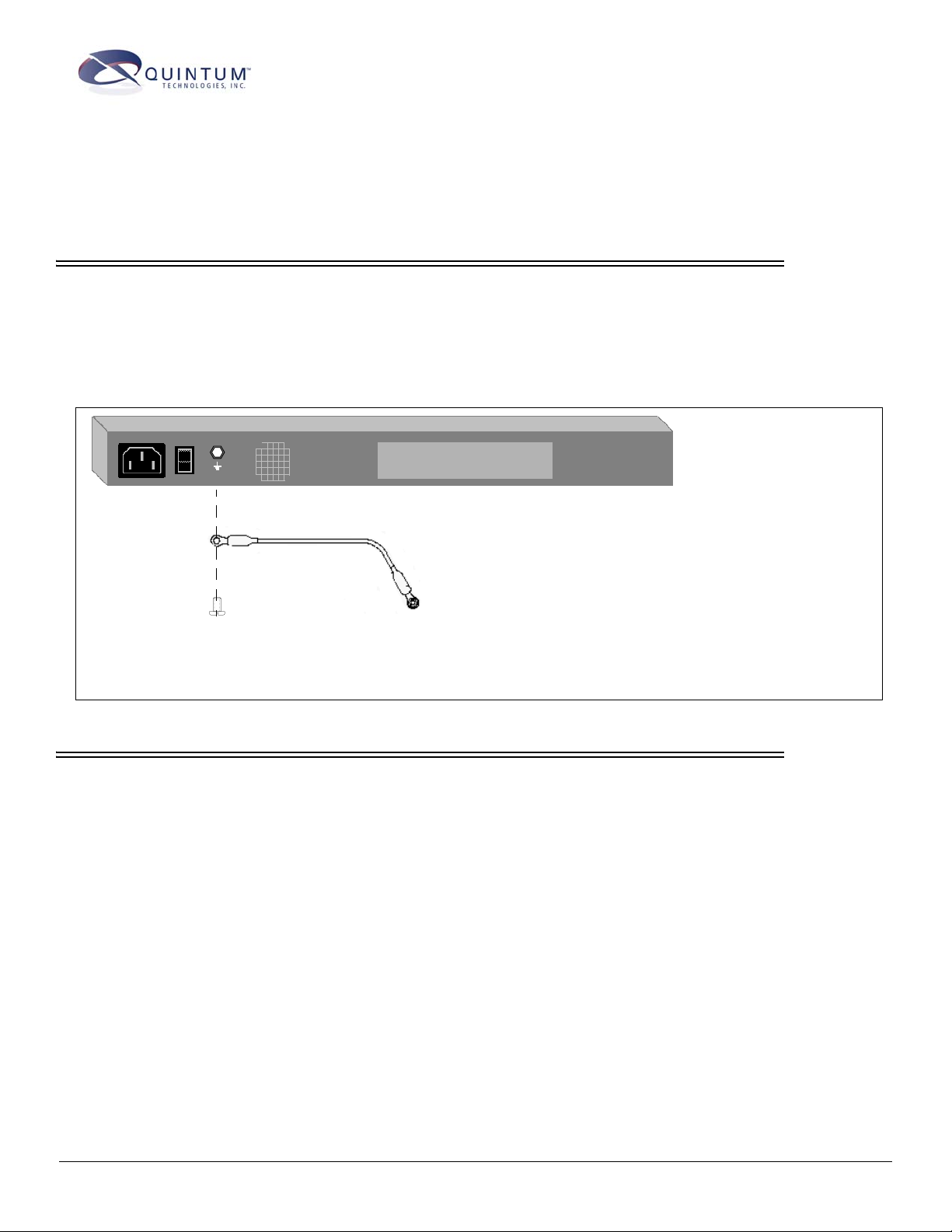
STEP 1: Install Ground Cable
The Tenor Call Relay 60 provides an Earth Ground point by way of a #6 screw at the rear panel. This screw
provides an additional functional Earth point, if required in your installation. Safety ground is provided
through the third wire of the AC power cord provided with your unit. For continued safe operation, a three
wire AC power cord must be used; failure to do so will void the warranty and Agency approvals.
Figure 1:
Install Ground Cable
1. Unscrew the existing screw from the grounding hole.
2. Place the screw through the connector of the ground cable.
3. Attach the screw securely to the threaded grounding hole.
4. Connect the other end of the ground cable to an approved
electrically grounded object. Consult with a licensed electrician if you are unclear about this operation.
STEP 2: Connect to Console Port
You will need to connect the Tenor Call Relay 60 to your workstation’s serial port via RS-232 connection.
(This connection will be used when you assign an IP address to the unit.) For the instructions below, it is
assumed you are connecting to a Windows PC.
480-0077-00-00
Page 2
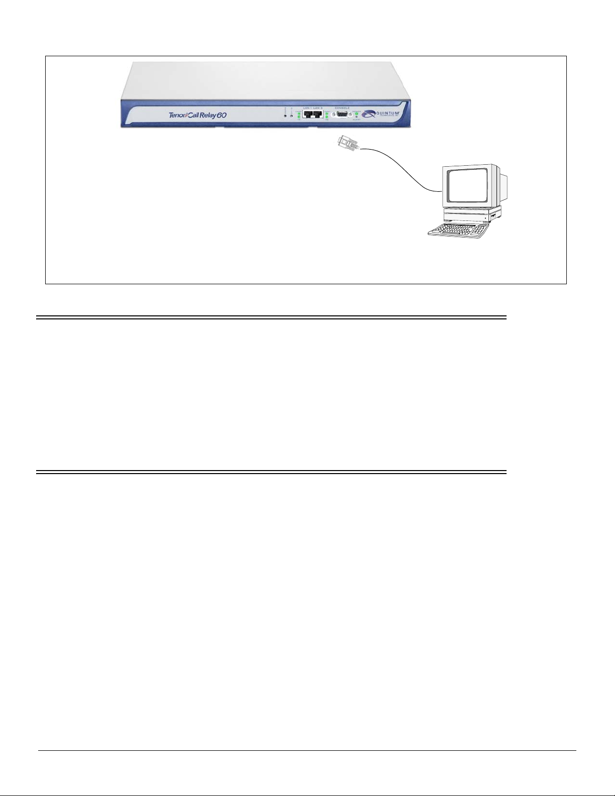
1. Insert the male end of the DB-9 cable into the port
labeled Console. (See the Tenor Call Relay 60 Product
Guide for RS-232 connector pinouts.)
2. Insert the female end of the DB-9 cable into your workstation’s serial port (see your PC documentation for
more information about this port).
STEP 3: Power up the System
Figure 2:
Connect to PC Com
DB-9
Once you have all cables connected properly, you are ready to turn the system on as follows:
1. Plug in the power cord to an AC outlet.
2. Locate the on/off switch on the back of the unit and click the switch to On.
The unit will power up and the LEDs will flash and turn off, the power LED will remain lit. Once the unit is powered
up, you are ready to assign an IP address.
STEP 4: Assign IP Address
Before you can configure the Call Relay 60, you need to assign a valid IP address. An IP address is a 32 bit (up to 12
numeric characters) address used to identify each network device in the TCP/IP network.
Assign IP address as follows:
1. Click on Start> Programs> Accessories> Communications> HyperTerminal> Run. The HyperTerminal window
will be displayed.
2. Click on Hyperterm.
3. Enter a Connection Description (i.e., name for each unit such as CR 60 NJ).
4. Click Ok.
5. Choose the connection port on your PC from the Connect Using drop down list box (i.e., Direct to Com 1). Click
Ok. The Com1 Properties window will be displayed. See
480-0077-00-00
Figure 3.
Page 3

Figure 3: Port Settings Window
6. From the Bits Per Second drop down list box, choose 38400.
7. From the Data Bits drop down list box, choose 8.
8. From the Parity drop down list box, choose None.
9. From the Stop bits drop down list box, choose 1.
10.From the Flow control drop down list box, choose None.
11.Click on Ok.
12.Click on Call>Call. A connection to the Call Relay 60 will be established.
13.After the bootup sequence, the login prompt will appear.
14.Enter a login name. The default login name is admin.
15.Enter a password. The default password is admin. Questions about the unit will scroll on the screen.
16.You will be asked to configure an Ethernet port. Enter Y to configure the Ethernet port.
NOTE: If you are unsure of the following values, contact your network administrator.
17.For IP address, enter the IP address for the Call Relay 60 unit.
18.For Subnet Mask prompt, enter the subnet mask. This address is used to differentiate the network portion of the IP
address from the host portion of the IP address.
19.For Default Gateway IP, choose whether there should be a default gateway (router) which routes packet data out-
side of your LAN, and enter its IP address.
The Tenor Call Relay 60 will automatically reboot with the new IP address.
480-0077-00-00
Page 4

STEP 5: Connect to Ethernet LAN
You can use these instructions for general connection purposes only. The Ethernet hub/switch manufacturer’s documentation should provide specific instructions for connection to another device, such as the Tenor Call Relay 60.
Only LAN 1 is available for use; LAN 2 is reserved for future use.
Figure 4: Connect to the Ethernet Hub/Switch
1. Plug one end of the grey
or white RJ-45 Ethernet cable into the
port labeled LAN 1.
2. Plug the other end of the cable into one
of the Ethernet hub/switch ports. If a
custom cable or adapter is required, see
Tenor Call Relay 60 Product Guide for
more information.
Data
Network
Ethernet Hub/Switch
71 James Way
Eatontown, New Jersey 07724
1.732.460.9000
1.732.544.9119 (fax)
480-0077-00-00
Technical Support:
Toll Free (U.S. Only):
1.877.435.7553
Internationally: 1.732.460.9399
Email:service@quintum.com
 Loading...