

Page 1
Tenor™ AX Quick Start
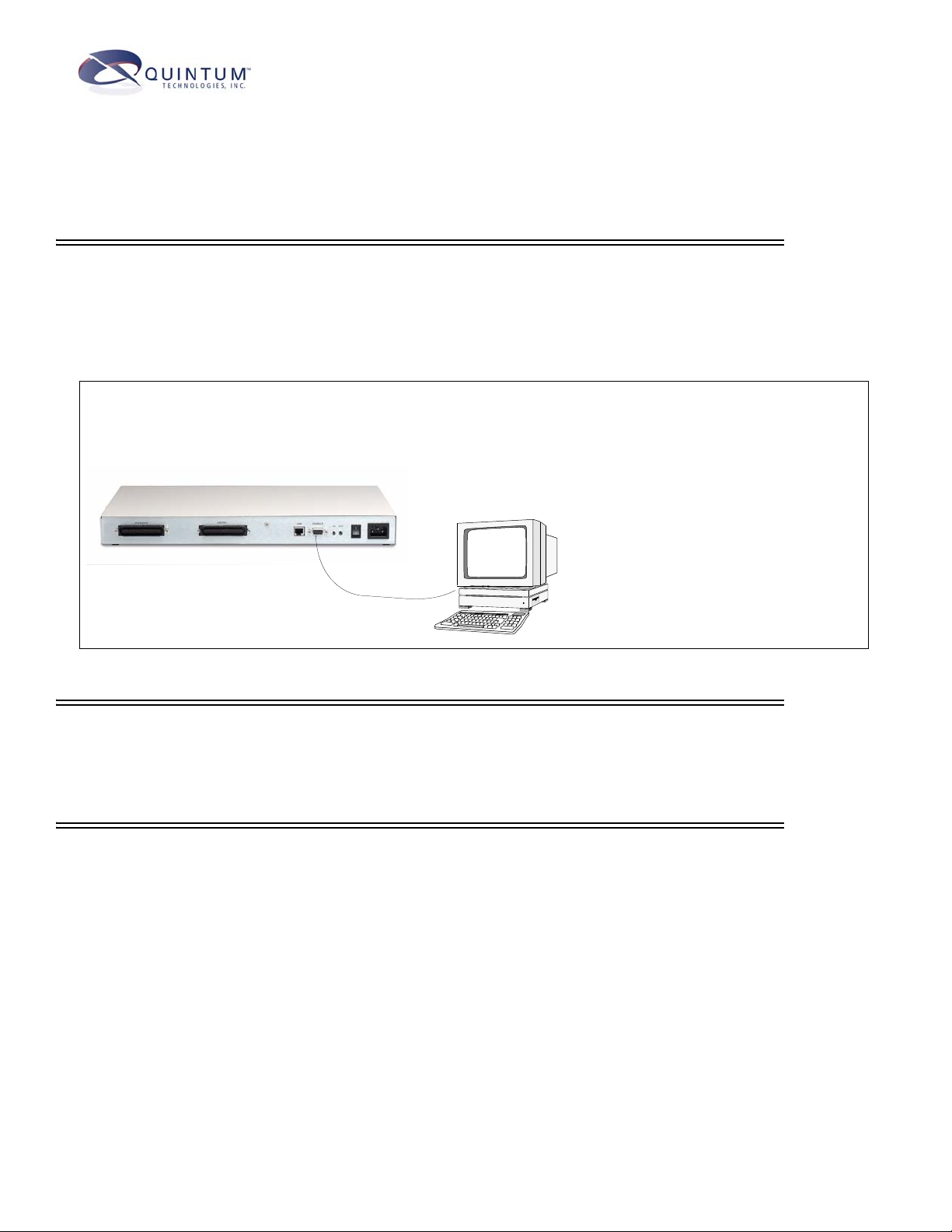
STEP 1: Connect to Console Port
Connect to PC Console. You will need to connect the Tenor AX to your workstation’s serial port through the RS-232 con-
nection. (This connection will be used when you assign an IP address to the unit.) For the instructions below, it is assumed you
are connecting to a Windows PC.
Figure 1: Connect to PC Com Port
1. Insert the male end of the DB-9 cable
into the port labeled Console.
2. Insert the female end of the DB-9 cable
into your workstation’s serial port (see
your PC documentation for more information about this port).
DB-9
STEP 2: Power Up the System
1. Plug in the power cord to an AC outlet.
2. Locate the on/off switch on the back of the unit and click the switch to On.
STEP 3: Configure Terminal Software/Assign IP address to Tenor AX
Before you can configure Tenor AX , you need to assign a valid IP address. When a Tenor AX is shipped to a customer, you need
to assign a valid IP address for each unit. An IP address is a 32 bit (up to 12 numeric characters) address used to identify each
network device in the TCP/IP network. If the unit does not have an IP address, data will not be able to be sent to or from the unit.
Communication between the Tenor and the PC is enabled via RS-232 connection and terminal emulation software. The instructions below assume you are running HyperTerminal (running Windows 95 or later) on your PC. For all other terminal emulation
packages, the specific Tenor commands used to assign the IP address will be the same, but the software specific instructions will
be different. Consult the applicable documentation for more information.
You can re-configure the IP address using the procedure which follows.
1. Press the Tenor AX’s power switch to On.
2. Click on Start> Programs> Accessories> Communications>HyperTerminal> Run. The Connection Description
window will be displayed.
3. Enter a connection name (i.e., name for each unit such as Tenor AX New Jersey).
Page 2
4. Click Ok.
5. Choose the serial port on your PC from the Connect Using drop down list box (i.e., Direct to Com 1). Click Ok.
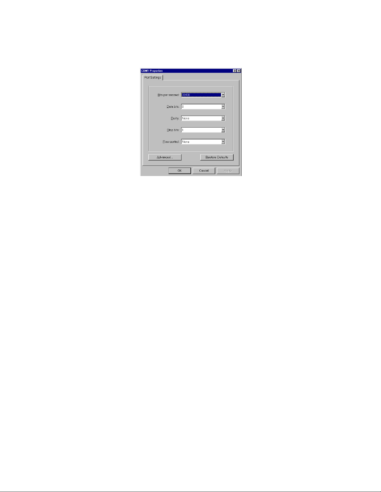
The Com1 Properties window will be displayed. See Figure 3-2.
Figure 3-2 Port Settings Window
6. From the Bits Per Second drop down list box, choose 38400.
7. From the Data Bits drop down list box, choose 8.
8. From the Parity drop down list box, choose None.
9. From the Stop bits drop down list box, choose 1.
10. From the Flow control drop down list box, choose None.
11. Click Ok and a connection to the Tenor will be established. Information about the unit will scroll on the screen.
12. Enter login and password. Both are admin by default.
13. A message will appear on the screen “Tenor Analog does not have an Ethernet interface configured. Would you
like to configure an Ethernet Interface?” (y/n).
14. Type y.
15. For IP Address, enter the IP address for the Tenor unit.
16. For Subnet Mask, enter the subnet mask. This address is used to differentiate the network portion of the IP address
from the host portion of the IP address.
17. For Default Gateway, choose whether there should be a default gateway (router) which routes packet data outside
of your LAN and enter its IP address.
18. A message will appear on the screen “Tenor Analog Ethernet Interface successfully configured.” The Tenor will
restart using the new Ethernet settings.
Tenor will restart using the new Ethernet settings.Once the IP information is set, you are ready to configure the unit
and make the first call. See the Tenor AX User’s Guide (included on your CD ROM) for details.
Page 3

STEP 4: Connect to Phone/FXS Interface
Depending on your order, you will have received either a double-ended or a single-ended 50-pin Telco cable. See the
Tenor AX User’s Guide (included on your CD ROM) for details for preparing the cables for connection (i.e., if you
ordered a single-ended cable, you must prepare it for use with your application).
Figure 3: Connect to Phone/FXS Interface
50 Pin Telco Connector
Break Out Box
Telephone
Fax
OR
PBX
PBX
See the Tenor AX Product guide for detailed caution information for connecting
the Phone/FXS port.
1. Plug one end of the 50-pin Telco cable into the port labeled
Phone/FXS.
2. Insert the other end of the 50-pin Telco cable into the appropri-
ate port on the PBX, key system, or another device that connects interfaces, such as a break out box. For the PBX
connection, see your PBX documentation port requirements for
connection specifics.
Step 5: Connect to Line/FXO Interface
You must first connect the analog phone lines to another piece of equipment that houses your telephone lines running to the
PSTN, such as a patch panel, punch down block or wire wrap blocks. If you are unsure of the installation procedures, contact the
network administrator or review the documentation you received with the PBX.
Figure 4: Connect to Line/FXO Interface
1. Plug one end of the 50-pin Telco cable into the ports
labeled Line/FXO.
2. Connect the other end of the 50-pin Telco cable into
the networking equipment (i.e. patch panel) which
50 Pin Telco Connector
Patch Panel
OR
Punchdown
Punchdown block
Block
houses your telephone line.
PSTN
Page 4

Step 5: Connect to Ethernet Hub/Switch (LAN)
You can use these instructions for general connection purposes only. The Ethernet hub/switch manufacturer’s documentation should provide specific instructions for connection to another device, such as the Tenor AX.
Figure 5: Connect to Ethernet Hub/Switch
1. Plug one end of the RJ-45 ethernet cable
into the port labeled LAN.
2. Plug the other end of the cable into one of
the Ethernet hub/switch ports.
RJ-45 Cable
Data
Network
Ethernet Hub/Switch
Step 6: Configuration
You are able to configure the unit through the Tenor Configuration Manager (for more information see the Tenor Configuration Manager/Tenor Monitor User’s Guide) or through the Command Line Interface (CLI) (see the Command
Line Interface User’s Guide). Both guides are available on the CD ROM you received with the unit.
71 James Way
Eatontown, New Jersey 07724
1.732.460.9000
1.732.544.9119 (fax)
Technical Support:
Toll Free (U.S. Only): 1.877.435.7553
Internationally: 1.732.460.9399
Email:service@quintum.com
 Loading...