

Page 1

®
V
ay
Tenor AS
oIP MultiPath/Gatew
Switch
d
u
c
P
r
o
4
P
/
N
t
0
8
-
0
0
u
G
0
0
-
1
5
9
0
-
i
d
e
Tenor and Quintum are registered trademarks. PacketSaver, Quintum Technologies, Inc., Risk Free VoP,
VoIP Made Easy, T ASQ, SelectNet, and SelectNet Technology are trademarks of Quintum Technologies,
Inc.
Page 2

Table of Contents
About this Guide
What’s included? . . . . . . . . . . . . . . . . . . . . . . . . . . . . . . . . . . . . . . . . . . . . . . . . . . . . . . . . . 1-2
Typographical Conventions . . . . . . . . . . . . . . . . . . . . . . . . . . . . . . . . . . . . . . . . . . . . . . . . . 1-3
Product Guide Conventions. . . . . . . . . . . . . . . . . . . . . . . . . . . . . . . . . . . . . . . . . . . . . 1-3
Finding Help. . . . . . . . . . . . . . . . . . . . . . . . . . . . . . . . . . . . . . . . . . . . . . . . . . . . . . . . . . . . . 1-4
Chapter 1: Overview
What is the Tenor AS?. . . . . . . . . . . . . . . . . . . . . . . . . . . . . . . . . . . . . . . . . . . . . . . . . . . . . 1-2
Features. . . . . . . . . . . . . . . . . . . . . . . . . . . . . . . . . . . . . . . . . . . . . . . . . . . . . . . . . . . . . . . . 1-4
Unique Design . . . . . . . . . . . . . . . . . . . . . . . . . . . . . . . . . . . . . . . . . . . . . . . . . . . . . . . 1-4
State-of-the-Art GUI Configuration and Network Management . . . . . . . . . . . . . . . . . . 1-4
Easy Connect to Console . . . . . . . . . . . . . . . . . . . . . . . . . . . . . . . . . . . . . . . . . . . . . . 1-4
Powerful System Monitoring . . . . . . . . . . . . . . . . . . . . . . . . . . . . . . . . . . . . . . . . . . . . 1-4
Capabilities . . . . . . . . . . . . . . . . . . . . . . . . . . . . . . . . . . . . . . . . . . . . . . . . . . . . . . . . . . . . . 1-5
SelectNet™ Technology Safety Net . . . . . . . . . . . . . . . . . . . . . . . . . . . . . . . . . . . . . . 1-5
PacketSaver™ reduces bandwidth consumption . . . . . . . . . . . . . . . . . . . . . . . . . . . . 1-5
Virtual Tie Trunk. . . . . . . . . . . . . . . . . . . . . . . . . . . . . . . . . . . . . . . . . . . . . . . . . . . . . . 1-5
SNMP Support. . . . . . . . . . . . . . . . . . . . . . . . . . . . . . . . . . . . . . . . . . . . . . . . . . . . . . . 1-6
Call Detail Recording . . . . . . . . . . . . . . . . . . . . . . . . . . . . . . . . . . . . . . . . . . . . . . . . . . 1-6
IVR/RADIUS Support . . . . . . . . . . . . . . . . . . . . . . . . . . . . . . . . . . . . . . . . . . . . . . . . . 1-6
NATAccess™. . . . . . . . . . . . . . . . . . . . . . . . . . . . . . . . . . . . . . . . . . . . . . . . . . . . . . . . 1-6
Dynamic Call Routing . . . . . . . . . . . . . . . . . . . . . . . . . . . . . . . . . . . . . . . . . . . . . . . . . 1-7
Tenor AS Call Paths . . . . . . . . . . . . . . . . . . . . . . . . . . . . . . . . . . . . . . . . . . . . . . . . . . . . . . 1-8
Tenor MultiPath Switch (ASM200 and ASM400) Configuration. . . . . . . . . . . . . . . . . . 1-8
Tenor VoIP Gateway (ASG200 and ASG400) Configuration. . . . . . . . . . . . . . . . . . . . 1-10
Advanced Features/Capabilities . . . . . . . . . . . . . . . . . . . . . . . . . . . . . . . . . . . . . . . . . . . . . 1-11
Call Management. . . . . . . . . . . . . . . . . . . . . . . . . . . . . . . . . . . . . . . . . . . . . . . . . . . . . 1-11
Dial Plan Options . . . . . . . . . . . . . . . . . . . . . . . . . . . . . . . . . . . . . . . . . . . . . . . . . . . . . 1-11
H.323 Gatekeeper Services. . . . . . . . . . . . . . . . . . . . . . . . . . . . . . . . . . . . . . . . . . . . . 1-12
SIP User Agent . . . . . . . . . . . . . . . . . . . . . . . . . . . . . . . . . . . . . . . . . . . . . . . . . . . . . . 1-14
Chapter 2: Hardware Components
Hardware Description . . . . . . . . . . . . . . . . . . . . . . . . . . . . . . . . . . . . . . . . . . . . . . . . . . . . . 2-2
Front Panel Connections and Reset Options. . . . . . . . . . . . . . . . . . . . . . . . . . . . . . . . 2-2
Back Panel. . . . . . . . . . . . . . . . . . . . . . . . . . . . . . . . . . . . . . . . . . . . . . . . . . . . . . . . . . 2-4
Cables. . . . . . . . . . . . . . . . . . . . . . . . . . . . . . . . . . . . . . . . . . . . . . . . . . . . . . . . . . . . . . . . . 2-8
P/N 480-0059-00-10 TOC-1
Page 3

RJ-11 Cables (for ASM200, ASG200) . . . . . . . . . . . . . . . . . . . . . . . . . . . . . . . . . . . . 2-8
RJ-11 Splitter Cable (for ASM400 and ASG400). . . . . . . . . . . . . . . . . . . . . . . . . . . . . 2-10
RJ-45 Cables . . . . . . . . . . . . . . . . . . . . . . . . . . . . . . . . . . . . . . . . . . . . . . . . . . . . . . . . 2-11
DB-9 Serial RS-232 Cable . . . . . . . . . . . . . . . . . . . . . . . . . . . . . . . . . . . . . . . . . . . . . . 2-12
Specifications. . . . . . . . . . . . . . . . . . . . . . . . . . . . . . . . . . . . . . . . . . . . . . . . . . . . . . . . . . . . 2-13
Voice/Fax. . . . . . . . . . . . . . . . . . . . . . . . . . . . . . . . . . . . . . . . . . . . . . . . . . . . . . . . . . . 2-13
PSTN/PBX Connections . . . . . . . . . . . . . . . . . . . . . . . . . . . . . . . . . . . . . . . . . . . . . . . 2-13
LAN Connection. . . . . . . . . . . . . . . . . . . . . . . . . . . . . . . . . . . . . . . . . . . . . . . . . . . . . . 2-13
Physical . . . . . . . . . . . . . . . . . . . . . . . . . . . . . . . . . . . . . . . . . . . . . . . . . . . . . . . . . . . . 2-13
Electrical . . . . . . . . . . . . . . . . . . . . . . . . . . . . . . . . . . . . . . . . . . . . . . . . . . . . . . . . . . . 2-13
Environmental . . . . . . . . . . . . . . . . . . . . . . . . . . . . . . . . . . . . . . . . . . . . . . . . . . . . . . . 2-13
Chapter 3: Installation/Basic Troubl eshooting
Installation . . . . . . . . . . . . . . . . . . . . . . . . . . . . . . . . . . . . . . . . . . . . . . . . . . . . . . . . . . . . . . 3-2
Pre-Installation Guidelines. . . . . . . . . . . . . . . . . . . . . . . . . . . . . . . . . . . . . . . . . . . . . . 3-2
Inspect Package Contents . . . . . . . . . . . . . . . . . . . . . . . . . . . . . . . . . . . . . . . . . . . . . . 3-2
Connect to Phone/FXS Interface . . . . . . . . . . . . . . . . . . . . . . . . . . . . . . . . . . . . . . . . . 3-3
Connect to Line/FXO Interface . . . . . . . . . . . . . . . . . . . . . . . . . . . . . . . . . . . . . . . . . . 3-4
Connect to Ethernet LAN . . . . . . . . . . . . . . . . . . . . . . . . . . . . . . . . . . . . . . . . . . . . . . . 3-5
Connect to PC Console . . . . . . . . . . . . . . . . . . . . . . . . . . . . . . . . . . . . . . . . . . . . . . . . 3-6
Install Supplemental Ground Safety Cable (if required) . . . . . . . . . . . . . . . . . . . . . . . . . . . 3-7
Power up the System. . . . . . . . . . . . . . . . . . . . . . . . . . . . . . . . . . . . . . . . . . . . . . . . . . . . . . 3-8
Assign IP address . . . . . . . . . . . . . . . . . . . . . . . . . . . . . . . . . . . . . . . . . . . . . . . . . . . . . . . . 3-9
Change IP Address . . . . . . . . . . . . . . . . . . . . . . . . . . . . . . . . . . . . . . . . . . . . . . . . . . . 3-10
Getting Started with Configuration/Making the First Call. . . . . . . . . . . . . . . . . . . . . . . . . . . 3-13
Load Software Upgrade. . . . . . . . . . . . . . . . . . . . . . . . . . . . . . . . . . . . . . . . . . . . . . . . . . . . 3-15
Common Symptoms/Problems . . . . . . . . . . . . . . . . . . . . . . . . . . . . . . . . . . . . . . . . . . . . . . 3-16
Chapter 4: Advanced Topic: View Call Detail Records
What is a CDR?. . . . . . . . . . . . . . . . . . . . . . . . . . . . . . . . . . . . . . . . . . . . . . . . . . . . . . . . . . 4-2
Establish connection between Teno r AS and CDR Server . . . . . . . . . . . . . . . . . . . . . . . . . 4-3
Configure Tenor AS for connection to CDR Server . . . . . . . . . . . . . . . . . . . . . . . . . . . 4-3
Setup CDR Server and assign password . . . . . . . . . . . . . . . . . . . . . . . . . . . . . . . . . . 4-4
Change CDR Password. . . . . . . . . . . . . . . . . . . . . . . . . . . . . . . . . . . . . . . . . . . . . . . . 4-5
Tenor AS Establishes Connection with CDR Server . . . . . . . . . . . . . . . . . . . . . . . . . . . . . . 4-5
CDR Server Establishes Connection with Tenor AS . . . . . . . . . . . . . . . . . . . . . . . . . . . . . . 4-5
CDR Output . . . . . . . . . . . . . . . . . . . . . . . . . . . . . . . . . . . . . . . . . . . . . . . . . . . . . . . . . . . . . 4-6
Sample Record for Standard and Extended CDR Format 0, 1, 100, 101 . . . . . . . . . . 4-6
Sample Record for Extended Tenor AS CDR Format 3, 4, 103, 104: . . . . . . . . . . . . . 4-10
Chapter 5: Advanced Topic: Diagnostics/Maintenance
Monitor LEDs. . . . . . . . . . . . . . . . . . . . . . . . . . . . . . . . . . . . . . . . . . . . . . . . . . . . . . . . . . . . 5-2
P/N 480-0059-00-10 TOC-2
Page 4

Monitor Alarms. . . . . . . . . . . . . . . . . . . . . . . . . . . . . . . . . . . . . . . . . . . . . . . . . . . . . . . . . . . 5-2
How to Read Alarms . . . . . . . . . . . . . . . . . . . . . . . . . . . . . . . . . . . . . . . . . . . . . . . . . . 5-2
Valid Alarms. . . . . . . . . . . . . . . . . . . . . . . . . . . . . . . . . . . . . . . . . . . . . . . . . . . . . . . . . 5-4
Display all Alarms . . . . . . . . . . . . . . . . . . . . . . . . . . . . . . . . . . . . . . . . . . . . . . . . . . . . 5-6
Display Active Alarms . . . . . . . . . . . . . . . . . . . . . . . . . . . . . . . . . . . . . . . . . . . . . . . . . 5-7
Display Alarm History. . . . . . . . . . . . . . . . . . . . . . . . . . . . . . . . . . . . . . . . . . . . . . . . . . 5-7
Verify Unit Provisioning . . . . . . . . . . . . . . . . . . . . . . . . . . . . . . . . . . . . . . . . . . . . . . . . . . . . 5-8
Maintenance Procedures. . . . . . . . . . . . . . . . . . . . . . . . . . . . . . . . . . . . . . . . . . . . . . . . . . . 5-8
Restore Factory Defaults . . . . . . . . . . . . . . . . . . . . . . . . . . . . . . . . . . . . . . . . . . . . . . . 5-8
Reset System. . . . . . . . . . . . . . . . . . . . . . . . . . . . . . . . . . . . . . . . . . . . . . . . . . . . . . . . 5-8
Change Password . . . . . . . . . . . . . . . . . . . . . . . . . . . . . . . . . . . . . . . . . . . . . . . . . . . . 5-9
Change Unit Date and Time . . . . . . . . . . . . . . . . . . . . . . . . . . . . . . . . . . . . . . . . . . . . 5-9
If you need Additional Help . . . . . . . . . . . . . . . . . . . . . . . . . . . . . . . . . . . . . . . . . . . . . . . . . 5-10
Chapter 6: Advanced Topic: SNMP/IVR
SNMP . . . . . . . . . . . . . . . . . . . . . . . . . . . . . . . . . . . . . . . . . . . . . . . . . . . . . . . . . . . . . . . . . 6-2
How does Tenor AS utilize SNMP? . . . . . . . . . . . . . . . . . . . . . . . . . . . . . . . . . . . . . . . 6-2
Installation Requirements . . . . . . . . . . . . . . . . . . . . . . . . . . . . . . . . . . . . . . . . . . . . . . 6-2
Install SNMP . . . . . . . . . . . . . . . . . . . . . . . . . . . . . . . . . . . . . . . . . . . . . . . . . . . . . . . . . . . . 6-3
Download and install SNMP-Related Files . . . . . . . . . . . . . . . . . . . . . . . . . . . . . . . . . 6-3
Configure Network Manager IP address . . . . . . . . . . . . . . . . . . . . . . . . . . . . . . . . . . . 6-5
Working with SNMP. . . . . . . . . . . . . . . . . . . . . . . . . . . . . . . . . . . . . . . . . . . . . . . . . . . . . . . 6-7
View traps . . . . . . . . . . . . . . . . . . . . . . . . . . . . . . . . . . . . . . . . . . . . . . . . . . . . . . . . . . 6-7
View Alarm Status via Tenor AS icon . . . . . . . . . . . . . . . . . . . . . . . . . . . . . . . . . . . . . 6-7
Launching Command Line Interface (CLI) from HP Openview . . . . . . . . . . . . . . . . . . 6-8
Set up Tenor AS status polling . . . . . . . . . . . . . . . . . . . . . . . . . . . . . . . . . . . . . . . . . . 6-8
Set up Debug Message Display window . . . . . . . . . . . . . . . . . . . . . . . . . . . . . . . . . . . 6-8
IVR. . . . . . . . . . . . . . . . . . . . . . . . . . . . . . . . . . . . . . . . . . . . . . . . . . . . . . . . . . . . . . . . . . . . 6-10
IVR Call Types. . . . . . . . . . . . . . . . . . . . . . . . . . . . . . . . . . . . . . . . . . . . . . . . . . . . . . . 6-10
ANI Authentication . . . . . . . . . . . . . . . . . . . . . . . . . . . . . . . . . . . . . . . . . . . . . . . . . . . . 6-11
Multi-session . . . . . . . . . . . . . . . . . . . . . . . . . . . . . . . . . . . . . . . . . . . . . . . . . . . . . . . . 6-11
Typical IVR Network Connection/Process. . . . . . . . . . . . . . . . . . . . . . . . . . . . . . . . . . . . . . 6-12
Configure IVR - Quick Start . . . . . . . . . . . . . . . . . . . . . . . . . . . . . . . . . . . . . . . . . . . . . . . . . 6-14
Basic IVR Data (via Trunk Group) . . . . . . . . . . . . . . . . . . . . . . . . . . . . . . . . . . . . . . . . 6-14
RADIUS Server . . . . . . . . . . . . . . . . . . . . . . . . . . . . . . . . . . . . . . . . . . . . . . . . . . . . . . 6-14
Configure IVR Voice Prompts . . . . . . . . . . . . . . . . . . . . . . . . . . . . . . . . . . . . . . . . . . . . . . . 6-16
Voice Prompt Requirements (English Requirements) . . . . . . . . . . . . . . . . . . . . . . . . . 6-16
Create Voice Prompt Files. . . . . . . . . . . . . . . . . . . . . . . . . . . . . . . . . . . . . . . . . . . . . . 6-20
IVR Call Flow - Specifications . . . . . . . . . . . . . . . . . . . . . . . . . . . . . . . . . . . . . . . . . . . . . . . 6-21
Pre-paid Calling Card - Call Flow (with default language) . . . . . . . . . . . . . . . . . . . . . . 6-21
P/N 480-0059-00-10 TOC-3
Page 5

Post-paid Calling Card - Call Flow (with default language) . . . . . . . . . . . . . . . . . . . . . 6-23
Pre-paid and Post-paid Calling Card - Call Flow (with multiple language support) . . . 6-25
Pre-paid and Post-paid Calling Card - Call Flow (with Multi-Session Call support). . . 6-26
ANI Authentication Application Type 1 - Call Flow. . . . . . . . . . . . . . . . . . . . . . . . . . . . 6-28
ANI Authentication Application Type 2 - Call Flow. . . . . . . . . . . . . . . . . . . . . . . . . . . . 6-30
Call Flow - Message Attributes . . . . . . . . . . . . . . . . . . . . . . . . . . . . . . . . . . . . . . . . . . . . . . 6-32
Start Accounting Request Message Attributes . . . . . . . . . . . . . . . . . . . . . . . . . . . . . . 6-32
Stop Accounting Request Message Attributes. . . . . . . . . . . . . . . . . . . . . . . . . . . . . . . 6-33
Authentication Request Message Attributes . . . . . . . . . . . . . . . . . . . . . . . . . . . . . . . . 6-35
Authentication Response Message Attributes . . . . . . . . . . . . . . . . . . . . . . . . . . . . . . . 6-35
Authorization Request Message Attributes . . . . . . . . . . . . . . . . . . . . . . . . . . . . . . . . . 6-36
Authorization Response Message Attributes . . . . . . . . . . . . . . . . . . . . . . . . . . . . . . . . 6-37
GLOSSARY
INDEX
Warranty/Approvals
Quintum Limited Warranty. . . . . . . . . . . . . . . . . . . . . . . . . . . . . . . . . . . . . . . . . . . . . . . . . . 1-3
Documentation Notice . . . . . . . . . . . . . . . . . . . . . . . . . . . . . . . . . . . . . . . . . . . . . . . . . . . . . 1-5
Agency Approvals . . . . . . . . . . . . . . . . . . . . . . . . . . . . . . . . . . . . . . . . . . . . . . . . . . . . . . . . 1-6
FCC WARNINGS. . . . . . . . . . . . . . . . . . . . . . . . . . . . . . . . . . . . . . . . . . . . . . . . . . . . . . . . . 1-7
Canadian Notice . . . . . . . . . . . . . . . . . . . . . . . . . . . . . . . . . . . . . . . . . . . . . . . . . . . . . 1-9
P/N 480-0059-00-10 TOC-4
Page 6

About this Guide
P/N 480-0059-00-10 Preface-1
Page 7

About this Guide
What’s included?
This product guide is divided into chapters; each chapter describes a specific topic. The following
chapters ar e included:
• About this Guide: Describes what is included in the Product Guide, including typographical
conventions.
• Chapter 1: Overview. In cludes a gen eral overv iew of th e product, in cludin g a descript ion of the
Tenor AS’s features and capabilities.
• Chapter 2: Hardware Components. Hardware description, including the front and rear panels,
as well as LEDs and required cables.
• Chapter 3: Installation/Basic Troubleshooting. Describes how to install the Tenor AS unit,
including how to connect, power up and assign the IP address.
• Chapter 4: Advanced Topic: View Call Detail Records. Describes the Call Detail Recording
(CDR) feature, including how to set up the CDR server and assign a password. In addition,
instructions for reading CDR output are also included.
• Chapter 5: Advanced Topic: Diagnostic/Maintenance: Describes how to troubleshoot and
monitor the health of the s ystem.
• Chapter 6: Advanced T opic: SNMP/IVR: This chapter d escribes the SNMP pro tocol an d how to
use it with the Tenor AS. In addition, it describes the Interactive Voice Response (IVR) system
for support of pre-paid and post-paid calls.
•Glossary
• Index
• Warranty
Preface-2 P/N 480-0059-00-10
Page 8

Typographical Conventions
Product Guide Conventions
Certain typographical conventions are used throughout this product guide. See below.
• All commands you enter via keystrokes appear in bold (e.g., Press Enter or Press Ctrl-I).
• All text commands you enter via Telnet session or command line typing appear in italics (e.g.,
type active).
• There are three types of special text that are designed to reveal supplemental information:
Note, Warning, and Caution. See below.
A NOTE provides additional, helpful information. This information may tell you how to do a
certain task or jus t be a remi nder for how-to’s given in previous sections. (i .e., For a l ist of va lid
commands at any time, type ?)
A WARNING provides information about how to avoi d harming your VoIP equipment or other
equipment (i.e., Do not stack more than 4 units together.)
About this Guide
A CAUTION provides informat ion about how to avoid injury t o yourself or to others (e .g., Do
not install the equipment during a lightning storm).
P/N 480-0059-00-10 Preface-3
Page 9

About this Guide
Finding Help
Refer to the Product Guide for help. The Table of Contents and Index tells you where to find information easily.
Extensive configuration help is available from the Tenor Configuration Manager/Tenor Monitor
User Guide or the Command Line Interfac e User Guide . Both documen ts are on the CDR ROM you
received with unit or you can download the latest documentation from www.quintum.com
Preface-4 P/N 480-0059-00-10
Page 10

Chapter 1: Overview
This chapter gives you a general overview of the Tenor AS including feature descriptions and capabilities. Specifically, the following topics are covered:
! A description of Tenor AS
! Features
! Capabilities
! Call Paths
! H.323 Gatekeeper Services
! Advanced Features
P/N 480-0059-00-00 1-1
Page 11
Chapter 1: Overview
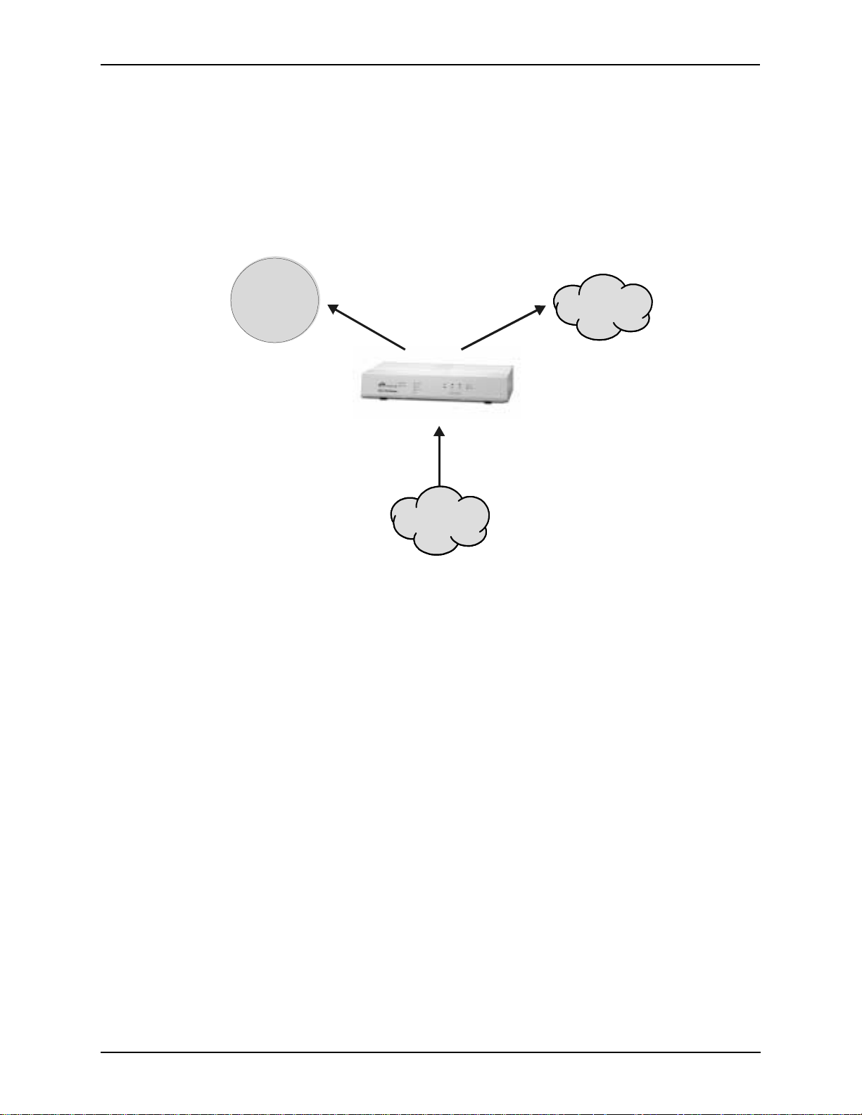
What is the T enor AS?
The Tenor AS is a VoIP (Voice over Internet Prot ocol) H.32 3/SIP swit ch that digiti zes voice , fax, and
modem data and transmits it over t he IP net wor k. De si gned as a SOHO produc t, the Tenor AS gives
small to medium sized businesses with analog voice infrastructure an easy, cost-effective way to
capitalize on the power of Voice over IP (VoIP).
The Tenor AS integrates a gate way, gatekeeper, bo rder element inte ll igent call rout ing, a nd supp orts
H.32/SIP and QoS all in on e so lut ion. The gateway converts c ir cui t swit ch ed calls to VoIP calls, the
gatekeeper performs IP call routing functions, and the border element distributes the call routing
directories throug hout th e networ k. Through t he FXS port , you can c onnect a tele phone, key syst em
or PBX; through the FXO port, you can connect to the PSTN (through direct connection to the Central Office).
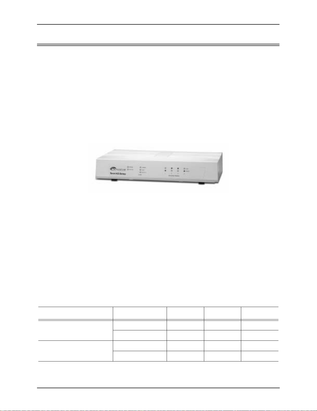
Figure 1-1
Tenor AS VoIP Switch
The Tenor AS is available in two configuration types:
• ASG VoIP Gateway. The ASG VoIP Gateway is mainly intended for applica tions interfa cing
between the PBX and the VoIP network. The number of VoIP channels equals the number of
FXS ports. Calls can be routed in any direction between any of the ports.
• ASM Multipath Switch. The AXM MultiPath Switch is mainly intended for symmetrical multipath applicatio ns, with an equa l n umber of FXO and FXS ports .The number of VoIP channels
is equal to half the number of telephony (i.e. PSTN) channels.
With its MultiPath architecture, the Tenor AS can intelligently route calls between the FXS,
FXO, and the VoIP network to achieve the best combination of cost and quality. The Tenor AS
also routes calls over IP to reduce costs, and then transparently “hops off” to the PSTN, to
reach off-net locations. Calls can be routed in any direction between any of the ports.
Table 1-1 Tenor AS Configuration Types
Series Configuration FXS Ports FXO Ports VoIP Ports
ASM200 2 2 2
ASM MultiPath
ASG VoIP Gateways
1-2 P/N 480-0059-00-00
ASM400 4 4 4
ASG200 2 0 2
ASG400 4 0 4
Page 12

Chapter 1: Overview
Whichever configuration you choose, the high performance unit provides one Autosensing BaseT
connection, along with one RS-232 serial console port connection. The unit also incorporates an
intelligent call routing engine which regulates system resources and configuration while coordinating all voice traffic activity in the unit.
The unit’s simple plug-and-play embedded system architecture brings VoIP technology to your network without changing your existing t el epho ny inf ra st ruc ture. Your network stays as is, an d t he call
type is transparent to the user. This technology boasts superior voice quality without compromising
reliability.
P/N 480-0059-00-10 1-3
Page 13

Chapter 1: Overview
Features
The Tenor AS’s specific features are explained below.
Unique Design
Tenor AS packs powerful VoIP features into one compact unit. The Tenor can be installed without
upgrades to the existing voice or data network. You can install the unit in a home or office environment, without affecting the network infrastructure you already have in place. As with all Tenor
architecture, the Tenor AS provides the power of VoIP in an easy-to-use product that takes just minutes to get up and running.
State- of-the-Art GUI Configuration and Network Management
The Tenor AS is managed/monitored by the Tenor Configuration Manager and Tenor Monitor.
Through the Tenor Configuration Manager, you can configure all options, such as dial plans, call
routing numbers, etc. An easy-to-use Java-based installation process enables you to an install the
manager and start configuring within minutes. Through the Tenor Monitor, you can monitor the
health of the system, including alarms, call detail records, etc. Both the Tenor Configuration Man-
ager and Tenor Monitor provide comprehensive on-line help systems that are available at your fin-
gertips.
In addition, you can configure the unit via Command Line Interface (CLI). Through this telnet session, you can access all configuration options, including an online help system, built into the CLI,
which provides help for all featur es and functions. Just type help at any prompt, and data about that
field will be displayed.
Easy Connect to Console
Plugging a serial cable between the unit’s RS-232 port and your PC’s console port, will allow local
unit management. Through the cons ole c onnect ion, yo u are able to as sign a n IP addr ess. I n addi tion ,
through the RS-232 port, you are able to configure the unit via Command Line Interface (CLI).
Powerful System Monitoring
There are many different ways to monitor the health of the unit, including LEDs and alarms. LEDs
appear on the front of the unit.The LEDs light up according to operations and alarms the system is
experiencing.
For more advanced monitoring , see Chapter 5: Advanced Topic: Diagnosti cs/Mainte nance to view a
list of active al arms, as well as view an alarm hi stor y. Each alarm indicates the uni t’s operational status.
1-4 P/N 480-0059-00-00
Page 14
Capabilities
SelectNet™ Technology Safety Net
Chapter 1: Overview
Quality of service is vi rtually guaranteed. Tenor AS ’s built-in patented SelectNet
™ T ec hnol ogy
provides a “safety ne t,” which virtually guar ant ee s that each call going VoIP will not only be routed
successfully, but will deliver high voice quality.
SelectNet monitors the IP network performance for VoIP calls. If the performance characteristics
become unacceptable—acc ording to the delay, jitter, and pa cket los s spe cificat ions you co nfi gure—
the Tenor AS will switch the call to the PSTN automatically and transparently. The Tenor continuously monitors your data network for jitter, latency and packet loss, and transparently switches customer calls to the PSTN when required.
PacketSaver™ reduces bandwidth consumption
PacketSaver packet multiplexing technology reduces the amount of IP bandwidth required to support multiple calls flowing between two endpoints. PacketSaver minimizes bandwidth usage by
aggregating packet samples from multiple VoIP conversations and packing them into a larger IP
packet with a single I P header. The process removes the need t o send a bulky I P header with i ndivid ual voice packets. As a result, it eliminates the transmission of redundant information.
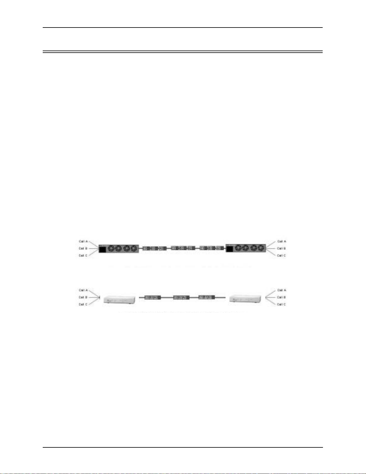
Figure 1-2 PacketSaver
Conventional VoIP Tran smi ssi o n Sends Man y R ed und an t Pack e t Heade r s
Tenor AS
Tenor
Tenor using PacketSaver to Minimize Ban dwidth Usage
Tenor AS
Tenor
Virtual Tie Trunk
The Tenor unit can emu la te any t ie tr unk. It provides all of t he functionality of a ti e t run k, including
the considerable cost savings, but eliminates the need for a PBX trunk to be configured, or marked
as a tie trunk. (A traditional tie trunk is a PBX-configured direct connection between two PBXs in
separate locations . The t ie tr unk bypa sses t he PSTN net work, whi ch res ults in cons id erabl e savi ngs.)
Your PBX does not need any additional configuration. The Tenor AS treats all trunks the same without compromising voice quality.
P/N 480-0059-00-10 1-5
Page 15
Chapter 1: Overview
SNMP Support
The Tenor AS supports Simple Network Management Protocol (SNMP), the standard protocol used
to exchange network information between different types of networks. The Tenor AS unit acts as an
SNMP agent—using HP®
Openview™—to receive commands and issue responses to the Network
Manager. The Network Manager will then be able to perform certain functions, such as receiving
traps from the Tenor AS.
Call Detail Recording
Through the Call Detail Record (CDR) feature, the Tenor AS generates a call record at the comple-
tion of each call, typically for accounting purposes. A CDR is a string of data that contains call
information such as call date and time, call duration, calling party, and called party. Tenor AS may
store Call Detail Records locally or they can be sent to a CDR server within the network. The CDR
contains sufficient information to capture billing data, which can be used to create billing reports
using third party billing software.
IVR/RADIUS Support
Interactive Voice Response (IVR) is a feature of the Tenor AS that enables you to of fer se rvices, such
as Pre-paid calling cards and Post-paid accounts, to your customers.
The Tenor uses the RADIUS (Remote Authentication Dial-In User Service), for authenticating and
authorizing user access to the VoIP network, including ANI Authentication (Types 1 and 2). The
RADIUS is a standard protocol which provides a series of standardized message formats for transmitting and rec eivin g dia led i nformat ion, acc ount d ata a nd aut horiz ation codes betwe en the network
access gateway and the billing server.
NATAccess™
NATAccess is an intelligent network address translation technology. It enables VoIP networks with
multiple H.323 endpoints to operate behind firewalls equipped with H.323 Network Address Translation (NAT); this provides maximum network security. NATAccess simplifies deployment by elim-
inating the need to place the Tenor on a public IP network. Using NATAccess provides easy, secure
expansion between muli tpl e VoIP sites. In addition, NAT technology in t he Tenor permits the use of
private subnets at the same time; in -house calls will never go over the public internet.
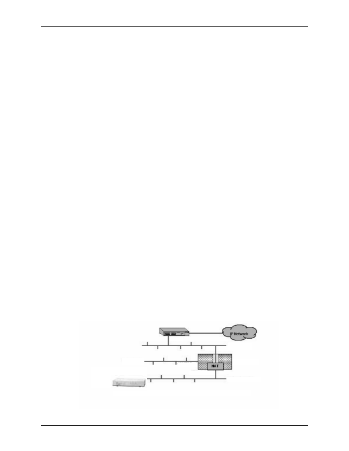
Figure 1-3 Tenor with NATAccess Deployment
Router
“Public” LAN
“DMZ” LAN
“DMZ” Port
“Private” port
Firwall NAT
“Private” LAN
1-6 P/N 480-0059-00-00
Page 16

Chapter 1: Overview
Dynamic Call Routing
Tenor AS’s intell igent c all rou ting capa biliti es are state-o f-the-a rt. Th e unit a utomati cally detects and
supports three call types: voice, fax, and modem.
Tenor AS will first identify the call origination site—Line/FXO, Phone/FXS, or IP routing group —
and then route the call according to the parameters you have configured in the routing database.
Each call may be routed via circuit switched path between any two circuit groups, or compressed
and transported via VoIP when connecting to an IP routing group. Trunk circuits are those that typically connect to another circuit switched network such as the PSTN. Line circuits typically connect
to a termination device on the user premises, such as a PBX.
P/N 480-0059-00-10 1-7
Page 17
Chapter 1: Overview
Tenor AS Call Paths
Tenor MultiPath Switch (ASM200 and ASM400) Configuration
The T eno r Mult iPath Switch Configur ation is symmetri cal with an equ al nu mber of Phone/ FXS and
Line/FXO ports. Calls are routed from the Phone/FXS, Line/FXO, or IP Network. Calls can be
routed in any direction between any of the ports.
FXS (Phone) Originated Calls. Calls coming from the Phone/FXS interface (i.e. PBX) may be
switched to either the d ata network a s a VoIP call or to the FXO interface , typical ly for c onnection to
another circuit switched network such as the PSTN. The routing decision made by the Tenor is
based upon your configuration and the dialed number. See Figure 1-4 for an example of a call originated from a PBX.
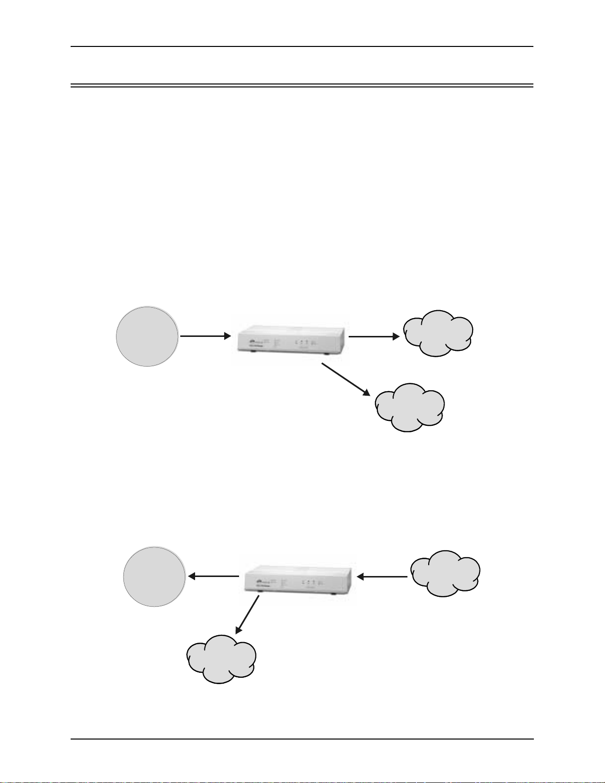
Figure 1-4 FXS (Phone) Originated Calls
PBX
Keyswitch
Phone
FXS Port
FXO Port
PSTN
OR
IP Network
FXO (Line) Originated Calls. A call coming from a Line/FXO inter face m ay be swit ched to ei ther
the data network as a VoIP call, a Line Circuit, or trunk typically for connection to a termination
device on the user’s premises such as a PBX. The routing decision made by the Tenor AS is based
upon your configuration and the dialed number. See Figure 1-5 for an example of a call originated
from the PSTN.
Figure 1-5 FXO (Line) Originated Calls
PBX
Keyswitch
Phone
FXS Port
OR
FXO Port
PSTN
IP Network
1-8 P/N 480-0059-00-00
Page 18
Chapter 1: Overview
IP Network Calls. Calls coming from the IP network ( data n etwork) can b e rout ed to th e Line/F XO
or Phone/FXS interfaces. The Tenor will route calls based upon the dialed number. If the number is
configured as a loc al phone number, the call will be sent to a Phone/FXS cir cuit for te rminat ion, otherwise the call is considered a “Hop-Off call” and the Tenor sends it out through a Line/FXO interface, typically co nnected t o the PSTN. See Figure 1- 6 for an example of a call originated from th e IP
network.
Figure 1-6 IP Network Originated Calls
PBX
Keyswitch
Phone
PSTN
FXS Port
OR
IP Network
FXO Port
P/N 480-0059-00-10 1-9
Page 19
Chapter 1: Overview
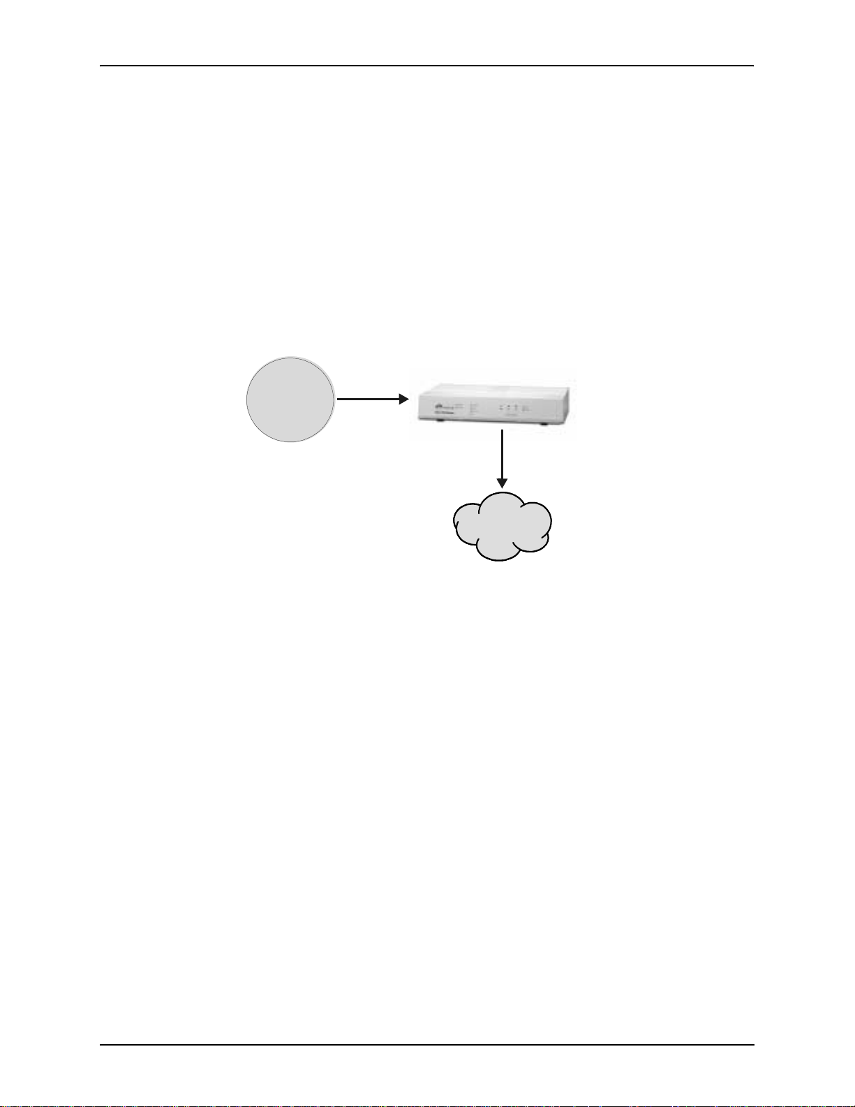
Tenor VoIP Gateway (ASG200 and ASG400) Configuration
The Tenor VoIP Gateway Configuration is used for Phone/FXS port connecting to the VoIP Network. The number of VoIP ports is equal to the number of FXS ports. Calls can be routed in any
direction between any of the ports. See Figure 1-7 for an example of a call origination from the
PBX.
FXS (Phone) Originated Calls. Calls coming from the Phone/FXS interface (i.e. PBX) may be
switched to the data network as a VoIP call. The routing decision made by the Tenor is based upon
your configuration and the dialed number. See Figure 1-7 for an example of a call originated from a
PBX.
Figure 1-7 FXS (Phone) Originated Calls
PBX
Keyswitch
Phone
FXS Port
IP Network
1-10 P/N 480-0059-00-00
Page 20

Chapter 1: Overview
Advanced Features/Capabilities
Call Management
There are four types of routing databases you can configure: Bypass Directory Numbers (BPN),
Hunt Local Directory Numbers ( Hunt LDN), Ho p-Of f Dir ectory Numbe rs (HDN) a nd S tati c Route s.
Bypass Directory Numbers. Bypass Directory Numbers (BDN) are telephone numbers that are
automatically routed directly from a line circuit to the PSTN; they will not be routed VoIP. Some
examples of bypass numbers include toll-free calls, emergency calls (i.e., 911), or high security
calls.
Hunt Local Directory Numbers. A Hunt Local Directory Number ((Hunt LDN) is a phone number
reachable through local Line Circuits.
Hop-Off Directory Number. A Hop-off PBX call travels over IP, and then “hops” off into the public network (PSTN) on t he destination side t o r ed uce or eliminate public t o l l cha rges (also known as
Leaky Area Map). A Hop -Off Directory Number i s routed over the IP to another Tenor location and
then out to the Trunk circuit, possibly to the PSTN as a local call.
Static Routes. Static Routes are used between networks and other H.323 devices that are not registered to the network through the Border Element (such as non-Quintum gateways). A static route
associates endpoints (as represented by their IP address) with Directory Number patterns.
Dial Plan Options
Public/Private Dial Plan Support.The Tenor AS supports public and private dial plans. A public
dial plan includes numbers which conform to the international dialing plan (E.164) of a country
code + city/area code + local number. For a public dial plan, you can define the numbering plan
structure for the Tenor AS to use for outgoing calls.
A private dial plan does not conform to a public dialing plan (i.e., 3 digit dialing plan); through the
Tenor AS you are able to configure the unique pattern/dialing plan structure, including number
length.
You are able to configure which dia l plan to use for incoming and outgoing call s, including whether
other options such as hop-off calls, will use a public or private dial plan.
User Programmable Dial Plan Support. The User Programmable Dial Plan Support (UPDP)
enables the Tenor to identify a completely customizable set of digit sequences, such as Local,
National, International or Private Numbers.
PassThrough support for certain call types. Certain call types can be directly routed to a trunk
circuit, without going IP. There are several routing tables you can configure via the Tenor Configu-
ration Manager to adj us t ho w the Tenor AS unit route s t hes e t ypes of “pass through” nu mb ers . For
example, you may want to conf i gure 911 as a “bypass number”, which means that al l 911 calls coming into Tenor AS from the line circuit will be routed directly to a Trunk circuit presumably con-
nected to a PSTN. Bypass calls are never routed over IP.
P/N 480-0059-00-10 1-11
Page 21

Chapter 1: Overview
Hop-off PBX Calls. Hop-off numbers are phone number patterns for calls to be routed out to the
PSTN. (A hop-off PBX call is a toll call which hops through a private network to reduce or eliminate the toll charge.) They are entered in a Hop-off Number Directory and associated with trunks
where matching calls should be sent.
Tenor AS supports those hop-off PBX calls where the destination Tenor AS is programmed to route
the call to the PSTN. The destination Tenor AS unit is configured with the phone numbers to be
“supported” for this feature.
H.323 Gatekeeper Services
The Tenor AS unit’s built-in H.323 gatekeeper performs IP call routing functions, such as call con-
trol and administrative services to another Tenor AS unit, or another H.323 endpoint. The gate-
keeper’s functionality complies with the H.323 industry specifications for voice control and
management.
Gatekeeper. A Gatekeeper in an H.323 network pro vides call control servi ce s and other services to
H.323 endpoints (i.e., gateways, terminals, and MCUs). The Tenor AS has a built-in H.323 gate-
keeper which complies to the H.323 industry specifications for voice control and management. The
gatekeeper performs call routing functions for calls entering and exiting a site.
The Gatekeeper pe rf orm s IP call routing f unc ti ons , such as Call Contro l Signaling and Call Authorization for Gateways, IP phones, and H.323 terminals. The Gatekeeper communicates with other
Gatekeepers through a Border Element. When using a group of Tenor AS units, you can assign one
unit as the Gatekeeper for the network. We recommend you configure each as its own gatekeeper.
Tenor AS supports gatekeeper to gatekeeper communication using the standard LRQ (Location
Request)/LCF (Location Confirm) messaging scheme.
Zone Management. A zone is a gr oup of H.323 defined endpoints controlled by a Gatekeeper. Endpoints can be gateways (i.e., Tenor AS), terminals, and/or multipoint conferencing units (MCUs).
Endpoints establ ish contr ol channe ls with a gatekeep er for r egistra tion, admi ssion, and secur ity. Call
routing information about the endpoint is sent to the gatekeeper, including: IP address, unit type
(gateway, terminal, or MCU) and routing information (such as phone numbers, number patterns,
etc.).
A collection of zones is an administrative domain. An administrative domain provides call routing
services for its zones through gatekeeper to gatekeeper messages or gatekeeper to border element
messages (see below for more information).
Call Registration. When registration from an H.323 endpoint is complete and a call is originated,
the call request is sent to the gatekeeper. The call request provides the Gatekeeper with the dialed
number and requests the routing information. The gatekeeper confirms the dialed number and supplies the endpoint with the destination IP address. For example, a Tenor AS’s gatekeeper will act as
the gatekeeper for that zone and all of the other endpoints will register with it.
Border Element. The Tenor AS’s gatekeeper uses a border element to gain access to the routing
database of the administrative domain for the purpose of call completion or any other services that
involve communication s with other endpoin ts ou t of the administr ative domain. The bo rder el ement
functionality is built into the Tenor AS unit, along with the gateway and gatekeeper.
P/N 480-0059-00-10 1-12
Page 22

Chapter 1: Overview
The primary function of the border element is to collect, manage, and distribute call routing information. A gatekeeper wil l e st abl is h a s er v ic e r el at ion shi p with a border element; th e ga tekeeper provides its zones capabilities and the border element shares call routing capabilities of other zones in
the administrative domain. Through the border element, gatekeepers from multiple zones will be
able to communicate.
A border element also establishes relationships with oth er border elements to route betwee n administrative domains. If a gatekeeper cannot resolve an address, it contacts the border element.
In addition, if you are us ing mo re than one Tenor unit, you can configure one of the bor der el ements
for that zone. The Tenor AS unit can use two border elements: primary and secondary. These work
together as one en ti ty to provide redund ancy and fault tolerance; there ar e no hierarchal differences.
Gatekeeper
Zone
Gatekeeper
Zone
Gatekeeper
Zone
Administrative Domain
Border Element
Border Element
Administrative Domain
Gatekeeper
Zone
Gatekeeper
Zone
Gatekeeper
Zone
Call Services. Gatekeepers provide services suc h a s a ddr essing, authorization and authenticati on of
terminals and gateways, bandwidth management, accounting, billing, and charging. Gatekeepers
also provide call-routing services. Specifically, the Tenor AS Gatekeeper provides the functions
which follow:
Address Translation. The gatekeeper translates telephone numbers into IP addresses and vice
versa. It performs Alias Addr ess (pho ne number) to T r ansport Address ( IP addres s) transl ation when
an endpoint requests service. The Gatekeeper uses a translation table to translate an Alias Address
(an address such as an H.323 identifier that a user may not understand) to a transport address. The
translation table is updated using Registration messages.
Autodiscovery. The gatekeeper is discovered i n one of t he foll owing ways: An endpoi nt sends a n IP
broadcast called a Gatekeeper Request message (GRQ) message (which includes that correct gatekeeper name) to disco ver a Gatekee per OR the endpo int will disc over a gate keeper by it s IP addres s.
Routing. The gatekeeper identifies the IP address of endpoints in its administrative domain. The
gatekeeper builds a routing database from information obtained from the border element and also
from gateways and H.323 endpoints.
Admissions Control. All H.323 endpoints must register and request permission to enter the gatekeeper’s zone; t he gatekeep er will conf irm or deny acc ess to the ne twork. The gatekeeper authorizes
P/N 480-0059-00-10 1-13
Page 23

Chapter 1: Overview
network access and protects the integrity of the network using Admission Request (ARQ), Admission Confirmation (ACF) and Admission Reject (ARJ) messages.
SIP User Agent
SIP (Session Initiat ion Protocol) is a sign al ing prot oc ol used to establish a se ss ion on an IP network
for voice control and management; it is a request-response protocol that closely resembles Hypertext Transfer Protocol (HTTP), which forms the basis of the World Wide Web. SIP re-uses many of
the constructs and concepts of Internet protocols such as HTTP and Simple Mail Transfer Protocol
(SMTP). The purpose of SIP is only to establish/change/terminate sessions. SIP is not concerned
with the content or details of the session.
SIP is Transport layer-independent, which means it can be used with any transport protocol: UDP,
TCP, ATM, etc. It is text-based, so it requires no encoding/decoding like H.323. And SIP supports
user mobility, using proxies and redirecting requests to your current location.
When configured for SIP the Te nor will act as a SIP User Agent (Endpoint) as defined in IETF
RFC3261. Multiple user ag ent s a ll ow f or separate agents t o be al lo cat ed to each SIP call. I t wil l b e
able to gateway calls to and from the IP network, and Customer Premise Equipment (CPE) such as
phones, PBX's, and FAX machines, or the Pu bli c Swit che d Telephone Network (PSTN). The Tenor
SIP User Agent will work in conjunction with an external SIP proxy or redirect server to route and
connect calls over SIP based networks.
There are three basic components of SIP:
1. User Agent (Endpoint)
• client element, initiate s calls
• server element, answers calls
2. Network Server (Proxy Server or Redirect Server)
• name resolution
• user location
• redirect an d forking
3. Registrar
• Stores registration information in a location service using a non-SIP protocol.
P/N 480-0059-00-10 1-14
Page 24

Chapter 2: Hardware Components
This chapter tells you what is contained in your hardware package. A description of each component
is also included.
Specifically, the following topics are covered:
! Hardware Description
! Cables
! Specification
P/N 480-0059-00-10 2-1
Page 25
Chapter 2: Hardware Components
Hardware Description
The Tenor AS is a stackable device which provides Phone/FXS and Line/FXO connections as well
as connections to the Ethernet LAN and a PC.
The unit’s front panel includes LEDs; the back panel includes connection jacks, a diagnostics
option, reset button, and an on/off power switch.
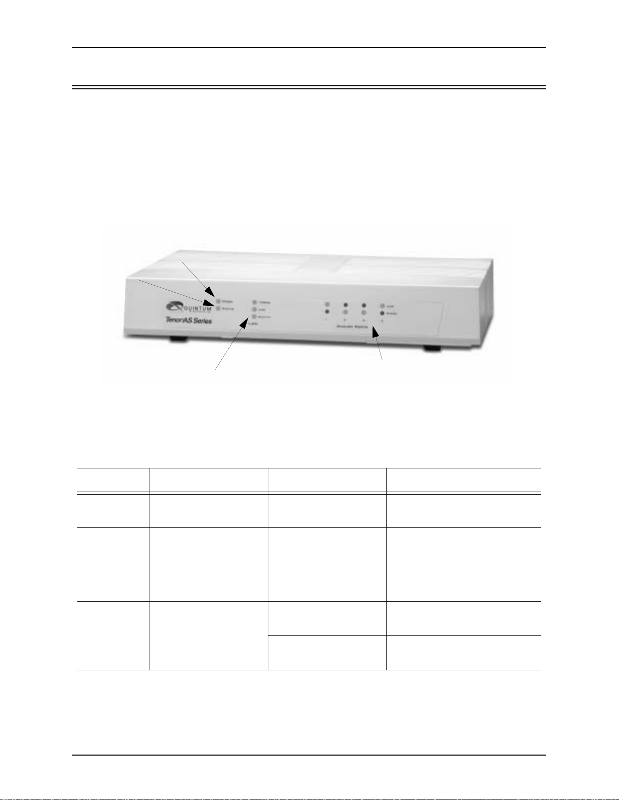
Front Panel Connections and Reset Options
Figure 2-1 Tenor AS Front Panel
Power LED
Status LED
LAN LEDs
Analog Port LEDs
The LEDs display the health of the system. There are differe nt types of LEDs: Power, Status, LAN
and Analog Ports. A description of each is described in Table 2-1.
Table 2-1 Front Panel LEDs Definitions
LED Label LED Color Description
Power Power Green On: Indicates power is on.
Off: Power is off.
Status Status Green Flashing Operational Statu s.
Off: Tenor AS is working properly.
On: One or more diagnostic
tests have failed.
Line LED - Green On indicates activity is occur-
ring on the Line/FXO port.
Analog Ports 1, 2 3, and 4
Phone LED - Green On indicates activity is occur-
ring on the Phone/FXS port.
2-2 P/N 480-0059-00-10
Page 26

Chapter 2: Hardware Components
LED Label LED Color Description
Link Green On: Link is working properly
and there is ac tivity on t he li ne.
Off: Link has failed.
LAN
100Mb Green On : The advertised link rate is
100Mb if the link is not connected, or the actual link rate is
100b if the link is connected.
Off: The advertised link rate is
10Mb if the link is not connected, or the actual link rate is
10Mb if the link is connected.
Activity Green Flashing On: indicates there is activity
(i.e., transmit/receive) on the
line.
Off: No activity is occurring.
P/N 480-0059-00-10 2-3
Page 27
Chapter 2: Hardware Components
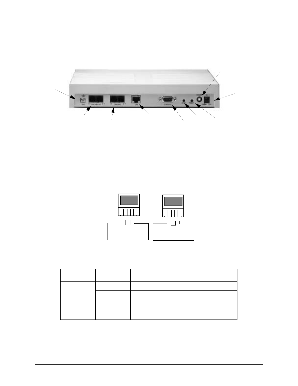
Back Panel
Ground
Screw
Power Switch
Power
Receptacle
Phone/FXS port
Line/FXO port
LAN port
Console
port
Diag
Reset
• Ground Screw. An earth ground screw is provided to connect to supplemental earth ground
using a Ground Safety Cable, if supplemental ground is needed.
• Phone/FXS port. Provides an RJ-11 jack for connection to a PBX, Keyphone or phone.
Figure 2-2 RJ-11 Phone/FXS Port Pin Order
Port 1
4 3 2 1
Pair 1
Pair 3
Port 2
4 3 2 1
Pair 2
Pair 4
Table 2-2 Input/Output RJ-11 Phone/FXS port
Pin # Used with Definition
1 Port 1, pin 4 Tip
Port 1
2-4 P/N 480-0059-00-10
2 Port 1, pin 3 Ring
3 Port 1, pin 2 Tip
4 Port 1, pin 1 Ring
Page 28
Chapter 2: Hardware Components
Pin # Used with Definition
1 Port 2, pin 4 Tip
Port 2
2 Port 2, pin 3 Ring
3 Port 2, pin 2 Tip
4 Port 2, pin 1 Ring
• Line/FXO port. Provides an RJ-11 jack for connection to the Central Office to provide direct
connection to the PSTN.
Figure 2-3 RJ-11 Phone/FXO Port Pin Order
Port 1
4 3 2 1
Pair 1
Pair 3
Port 2
4 3 2 1
Pair 2
Pair 4
Table 2-3 Input/Output RJ-11 Phone/FXS port
Pin # Used with Definition
1 Port 1, pin 4 Tip
Port 1
Port 2
2 Port 1, pin 3 Ring
3 Port 1, pin 2 Tip
4 Port 1, pin 1 Ring
1 Port 2, pin 4 Tip
2 Port 2, pin 3 Ring
3 Port 2, pin 2 Tip
4 Port 2, pin 1 Ring
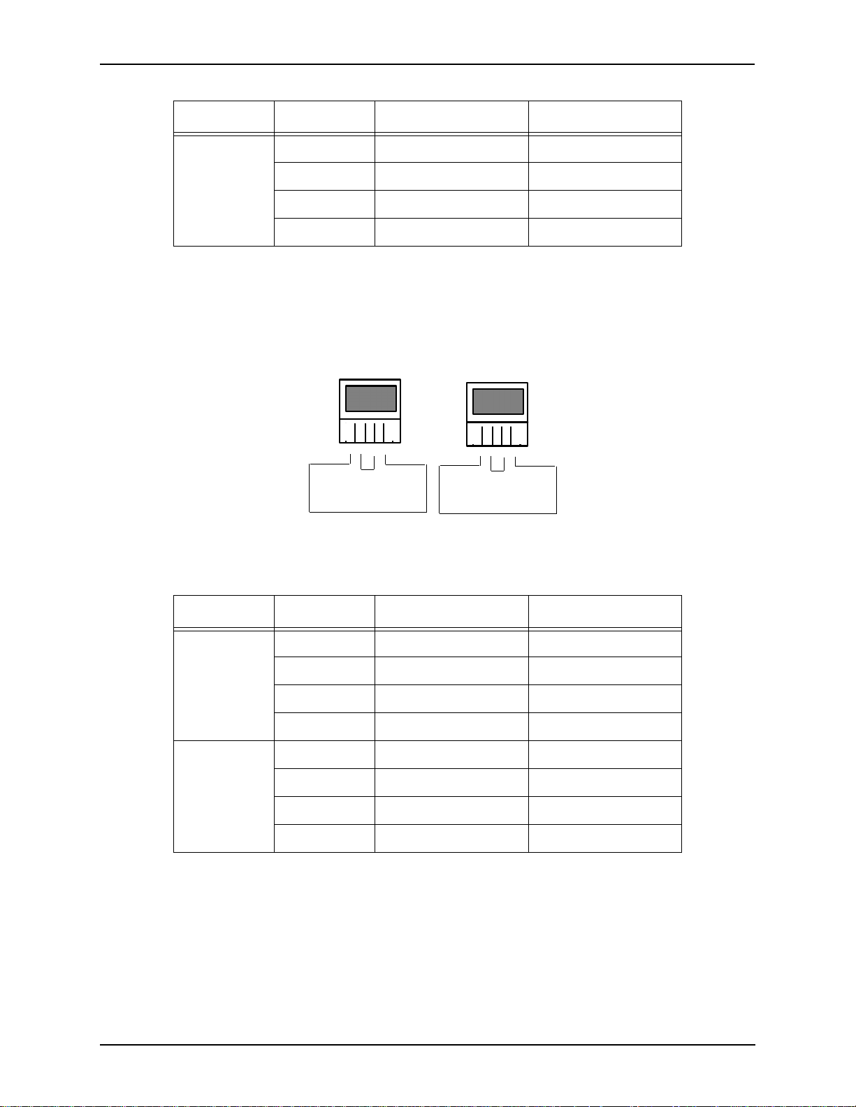
• LAN port. 10/100 Base-T Ethernet port. This port provides an RJ-45 jack for an individual
connection to a 10/100 Ethernet LAN switch or hub via RJ-45 cable; it is individually configured with a unique IP and MAC address.
P/N 480-0059-00-10 2-5
Page 29
Chapter 2: Hardware Components
Figure 2-4 10/100 BASE-T Ethernet Port Pin Order
Table 2-4 Input/Output 10/100 Ethernet port
Pin # Signal Definitio n Color
1 TX + Transm it Data White w/orange
2 TX - Transmit Data Orange
3 RX + Receive Data White w/green
4 RSVD Reserved Blue
5 RSVD Reserved White w/blue
6 RX - Receive Data Green
7 RSVD Reserved White w/Brown
8 RSVD Reserved Brown
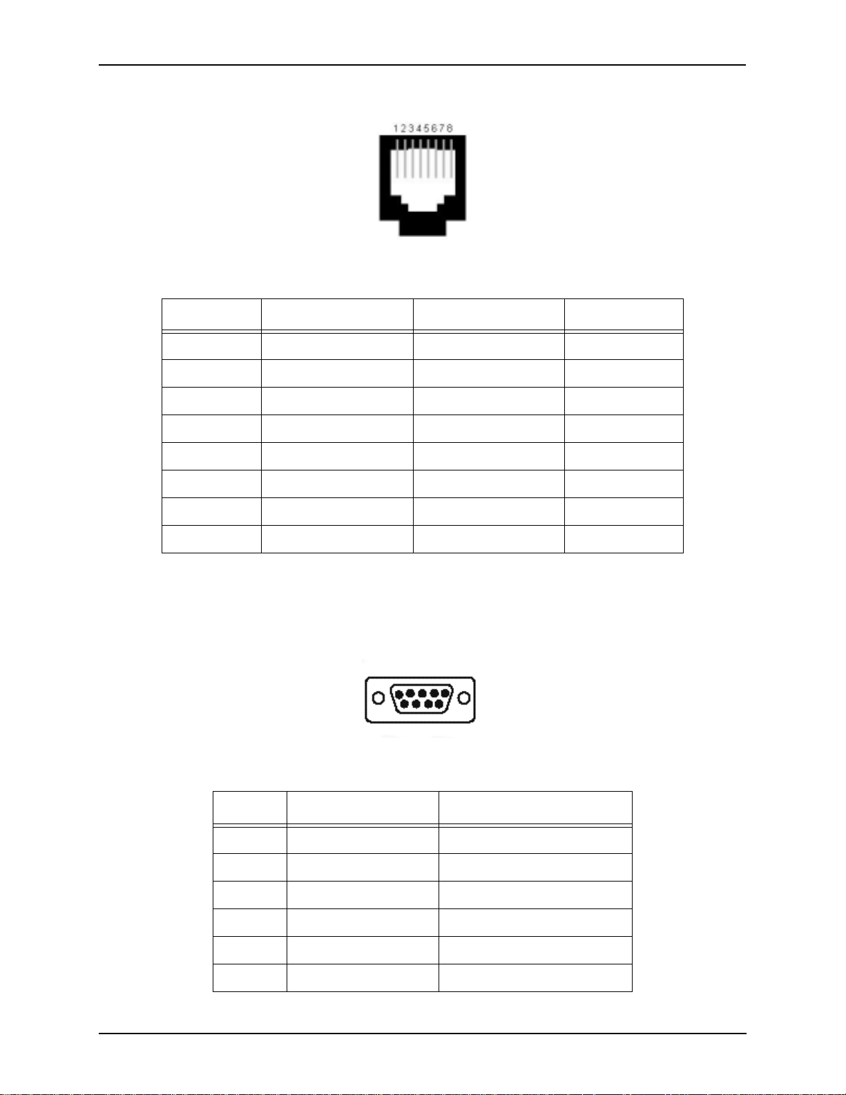
• Console port. This RS-232 connector is used for connection to a PC’s serial port via DB-9
serial cable at 38400 BPS 8N1, without flow control. The input/output signals are listed in
Table 2-5.
Figure 2-5 DB-9 Female Connector Pin Order
5 4 3 2 1
9 8 7 6
Table 2-5 Serial RS232 DB-9 Connector Pinouts
Pin # Function Description
1 DTR Data Terminal Ready
2 TXD Transmit Data
3 RXD Receive Data
4 CD Carrier Detect
5 GND Signal Ground
6 N.C. No Connect
2-6 P/N 480-0059-00-10
Page 30

Chapter 2: Hardware Components
Pin # Function Description
7 N.C. No Connect
8 N.C. No Connect
9 N.C. No Connect
• Diag. Enables you to perform software diagnostic procedures.
• Reset. Enables you to reset the system. See
Chapter 5: Advanced Topic: Diagnostics/Maintenance
for more information.
• Power Switch. Switch to turn power on and off.
• Power Socket. Connection port to external power supply block.
P/N 480-0059-00-10 2-7
Page 31

Chapter 2: Hardware Components
Cables
The cables listed in Table 2-6 are required to connec t a Tenor AS to various inter faces . Contac t Quin tum for ordering information, if necessary.
Table 2-6 Cables Supported
Cable Usage
RJ-11 to RJ-11 Cable Connection to FXO/Line. (For the AS400 unit.
a Dual Port Splitter Cable is required.)
RJ-11 to RJ-11 Cable Connectio n to FXS/Phone . (For the AS400
unit, a Dual Port Splitter Cable is required.)
RJ-11 Splitter Cable Connection to ASM400 units enabled for four
FX0 ports or to ASM400 units enabled for
four FXS port s.
RJ-45 Ethernet cable Connection to Ethernet LAN 10/100
DB-9 Serial RS-232 Connection to PC’s asynchronous console
port.
AC power adaptor/cord One AC power adapter/cord for connection to
AC power jack.
RJ-1 1 Cables (for ASM200, ASG200)
An RJ-11 c abl e i s us ed t o connect the Tenor AS to an FXO or FXS external device. The RJ-11 cable
connector pinouts are given in this section to help you identify the proper connector to accommodate your specific networking requirements. The RJ-11 connector is the EIA/TIA standard for
Unshielded Twisted Pair (UTP) cable; the wiring color codes are UTP Standard Coloring. The pin
order is shown in Figure 2-6.
Figure 2-6 RJ-11 Pin Order
4
1
To p View
1
4
2-8 P/N 480-0059-00-10
Page 32

Chapter 2: Hardware Components
Pin # Connects to Pin #
Figure 2-7 RJ-11 Connector Pinouts
1
2
3
4
1
Table 2-7 RJ-11 Connector Pinouts
Pin # Definition
1TIP
2Ring
3Tip
4Ring
2
3
4
P/N 480-0059-00-10 2-9
Page 33

Chapter 2: Hardware Components
RJ-11 Splitter Cable (for ASM400 and ASG400)
An RJ-11 c abl e i s us ed t o connect the Tenor AS to an FXO or FXS external device. The RJ-11 cable
connector pinouts are given in this section to help you identify the proper connector to accommodate your specific networking requirements. The RJ-11 connector is the EIA/TIA standard for
Unshielded Twisted Pair (UTP) cable; the wiring color codes are UTP Standard Coloring.
The RJ-11 Splitter cable’s single end is labeled Tenor (see Figure 2-9); the split ends can be a 6-pin
jack (accepts 4-pi n plug or 6- pin plug) or 4-pin pl ug. Each e nd is la beled A or B (se e Fig ure 2-9 ) fo r
pin order.
For illustration purposes, the 4-pin plug is shown in Figure 2-8.
Figure 2-8 RJ-11 Splitter Cable
4
1
Tenor
Top View
Figure 2-9 RJ-11 Splitter Cable Pin Order
Pin# Connects to Pin#
1
1
4
2
3
2
3
4
1
2
3
4
1
4
1
4
B
A
P/N 480-0059-00-10 2-10
Page 34

RJ-45 Cables
Pin # Connects to Pin #
RJ-45 cable connector pinouts are given in this section to help you identify the proper connector to
accommodate your specific networking requirements. The RJ-45 (ISO 8877) connector is the EIA/
TIA standard for Unshielded Twisted Pair (UTP) cable; the wiring color codes are UTP Standard
Coloring. The pin order is shown in Figure 2-1.
Figure 2-1 RJ-45 Pin Order
Side View
8
1
Top View
1
8
RJ-45 Ethernet Cable (10/100)
An RJ-45 (10/100BaseT) strai ght thr ough shielded cable is used to con nec t Tenor AS to an Ethernet
LAN. Cable pinouts are listed in Table 2-1. Color specifications are applicable to the RJ-45 cable
provided.
Figure 2-2 RJ-45 (10/100BT) Connector Pinouts
1
2
3
4
5
6
7
8
1
2
3
4
5
6
7
8
Table 2-1 RJ-45 (10/100BT) Connector Pinouts
Pin # Signal Definitio n Color
1 TX + Transmit Data White w/orange
2 TX - Transmit Data Orange
3 RX + Receive Data White w/green
4 Unused Unused Blue
5 Unused Unused White w/blue
P/N 480-0059-00-10 2-11
6 RX - Receive Data Green
7 Unused Unused White w/Brown
8 Unused Unused Brown
Page 35

DB-9 Serial RS-232 Cable
Pin #
Connects to
Pin #
The Serial RS-232 9-pin cable with a DB-9 male connector (with RS-232 interface) is used to connect the Tenor AS to your PC’s asynchronous serial port. The pin order for DB-9 male and female
connectors are shown in Figure 2-3 and Figure 2-4.
Figure 2-3 DB-9 Male Connector Pin Order
1 2 3 4 5
6 7 8 9
Figure 2-4 DB-9 Female Connector Pin Order
5 4 3 2 1
9 8 7 6
Figure 2-5 DB-9 Connector Pinout s
1
2
3
4
5
6
7
8
9
1
2
3
4
5
6
7
8
9
Table 2-2 DB-9 Co nnector Pinouts
Pin # Function Description Pin #
1 DTR Data Terminal Ready 1
2 TXD TransmitData 2
3RXD Receive Data 3
4 CD Carrier Detect 4
5 GND Signal Ground 5
6 N.C. No Connect 6
7 N.C. No Connect 7
8 N.C. No Connect 8
9 N.C. No Connect 9
P/N 480-0059-00-10 2-12
Page 36

Chapter 2: Hardware Components
Specifications
Voice/Fax
Call Routing: FXO/FXS/IP
Coding: A-law, mu-law
Voice Algorithms: G.723.1A (5.3, 6.3 Kbps), G.726 (16, 24, 32, 40 Kbps), G.729A, G711
Fax Support: Group III at 2.4, 4.8, 7.2, 9.6, 12, 14.4 Kbps
Automatic C all Detection:Voice /Modem/Fax
PSTN/PBX Connections
Interface: Analog, FXO Interface (PSTN side), FXS Interface (PBX side)
Connector: RJ-11
Ringing Cadence: Adjustable, country-dependent
Maximum Loop Current: 24 mA
Ringer Equivalence Number:3 up to 1000 feet of 24 AWG or heaver)
Ringing Frequency: Adjustable, country-dependent
Ringing Voltage: Adjustable, country-dependent
LAN Connection
LAN Support: 10/100 Mbps Ethernet
Connection Type: Autosensing of speed and duplex
Physical
Depth: 7” (18.73 cm)
Height: 2” (5.1 cm)
Width 10 1/8 (24.5 cm)
Weight: 3.5 lbs (1.6 kg)
Electrical
Ethernet: Standard 10/100Base-T RJ-45 interface (IEEE 802.3)
FXO/FXS: Standard RJ-11 connectors
Connectors: 2 RJ-11 connectors for FXO connection
2 RJ-11 connectors for FXS connection
Console Port: RS-232/DB-9 Female
Power: 12Vdc at 1.2A max. Wall adapter is supplied with each unit to derive
the 12Vdc needed
Environmental
Operating Temperature: 40° to 104° F (5 - 40° C)
Operating Humidity: 10% to 90% non-condensing
Altitude: -200 to 10,000 feet, or -60 to 3,000 meters
Storage Temperature: 14° to 140° F, or -10° to 60° C
P/N 480-0059-00-10 2-13
Page 37

Chapter 3: Installation/Basic
Troubleshooting
This chapter give s you in stall atio n inst ructi ons, as well as how t o posi tion t he Tenor AS successfully
within your network.
Specifically, the following topics are covered:
! Installation
! Install Ground Safety Cable
! Power up the System
! Assign IP Address
! Load Software Upgrade
! Getting Started with Configuration
! Common Symptoms Problems
P/N 480-0059-00-10 3-1
Page 38

Chapter 3: Installation/Basic Troubleshooting
Installation
Before you begin the actual installation, review the pre-installation guidelines which follow and
inspect the package contents.
Pre-Installat ion Guidelines
• Always use an anti-static wrist strap when handling the unit.
• Do not open the unit cover. Inside parts have hazardous voltages and are ext reme ly sensi tive to
static. If th e unit has been opened, your warranty is void.
• Do not connect equipment in wet conditions and keep away from dusty areas.
• The area must not exceed the temperature and humidity guidelines outlined in Chapter 2:
Hardware Components.
• Avoid exposing the unit to excessive vibrations.
• Ensure no equipment is put on top of the chassis.
Inspect Package Contents
Before you in stall the hardware, ensure the following components are incl uded in your shipment:
• Tenor AS
• 1 AC Power adaptor/cord
• 1 DB-9 RS-232 Serial Cable
• RJ-45 Cable
• Product Guide in CD format
If a listed component is not included in your package, contact your customer service representative.
3-2 P/N 480-0059-00-00
Page 39

Chapter 3: Installation/Basic Troubleshooting
Connect to Phone/FXS Interface
Since there are many different PBX devices, keys systems, fax machines and phones you can connect to the Tenor AS, the instructions which follow explain the general procedure for connecting an
RJ-11 ca ble (incl uded in your package) b etween the P hone/FXS po rt and an ex ternal de vice. Use th e
phone/FXS ports for on-premise wiring only.
For the ASM200 and ASG200, you can connec t one devi ce t o eac h FXS por t. For the ASM400 and
ASG400, you can co nnect two devices to each FXS port (using an RJ-11 Dual Port Splitter).
See Chapter 2: Hardware Components for the RJ-11 cable pinouts you can use to acquire another
cable or adaptor that may be required to connect to the specific external device.
Figure 2-1 Connect to Phone/FXO port
RJ-11
RJ-11 Dual Port Splitter
For ASM400, an RJ-11 Dual Port Splitter
Cable is used in each port enabled for 4 FXS
ports.
Phone
PBX
Connect to Phone/FXS port as follows:
CAUTION: Connect the Phone/FXS ports to a telephone, fax machine, PBX or key system only.
Connecting to other dev ices/netw orks (i.e., t elephone wal l jack) will cause dama ge to
the unit.
1. Plug one end of the RJ-11 cable into one of the two ports on the front of the unit labeled Phone/FXS. See
Chapter 2: Hardware Components for cable pinouts.
2. Insert the other end of the RJ-11 cable into the appropriate analog port on the PBX or key system, or into
the jack on the back or under side of t he ph one or fax mach ine. For the PBX connection, see y our PBX documentation port requirements for connection specifics.
P/N 480-0059-00-10 3-3
Page 40

Chapter 3: Installation/Basic Troubleshooting
Connect to Line/FXO Interface
To connect to the Line/FXO port, you must first connect the analog phone lines to another piece of
equipment that houses your telephone lines running to the PSTN, such as the patch panel, punch
down block or wire wrap blocks. If you are unsure of the installation procedures, contact the network administrator or review the documentation you received with the PBX.
For the ASM200 and ASG200, you can connect one device to each Line/FXO port. For the
ASM400 and ASG400, you can connect two devices to each Line/FXO port (using an RJ-11 Dual
Port Splitter).
See Chapter 2: Hard ware Components for the RJ-11 cable pinouts you can use to acquire another
cable or adaptor that may be required to connect to the specific external device.
Figure 2-2 Connect to Line/FXO Interface
RJ-11 Dual Port Splitter
For ASM400, an RJ-11 Dual Port Splitter
Cable is used in each port enabled for 4 FX0
RJ-11
Patch Panel
Punchdown
Punchdown block
Block
ports.
PSTN
1. Plug one end of the RJ-11 cable into one of the ports labeled Line/FXO. See Chapte r 2: Hardware Com-
ponents for cable pinouts if you are making your own cable.
2. Connect the other end of the RJ-45 straight cable to the patch panel (or other external device) which
houses your telephone lines.
NOTE: Connecting to the patch panel may require trained telephone personnel.
3-4 P/N 480-0059-00-00
Page 41

Chapter 3: Installation/Basic Troubleshooting
Connect to Ethernet LAN
You can use these instructions for gener al conn ectio n purpose s only. The Ethernet hub/switch manufacturer’s docu mentati on should provi de specifi c instruction s for conne ction to anoth er device, such
as the Tenor AS.
Figure 2-3 Connect to Ethernet Hub/Switch
Data
Network
Ethernet Hub/Switch
1. P l ug one end RJ-45 Et hern et cable into the port labeled LA N.
2. Plug the other end of the cable into one of the Ethernet hub/switch ports. If a custom cable or adapter is
required, see Chapter 2: Hardware Components for the Ethernet RJ -45 10/100.
P/N 480-0059-00-10 3-5
Page 42

Chapter 3: Installation/Basic Troubleshooting
Connect to PC Console
You will need to connect the Tenor AS to your workstation’s serial port via RS-232 connection.
(This connection will be use d whe n you as sign an IP addres s to t he unit .) For the in str ucti ons bel ow,
it is assumed you are connecting to a Windows PC.
Figure 2-4 Connect to PC Com Port
DB-9
1. Insert the male end of the DB-9 cable into the port labeled Console. (See Chapter 2: Hardware Compo-
nents for RS-232 connector pinouts.)
2. In sert the female end of the DB-9 cable into your workstation’s serial console port (see your PC documentation for more information about this port).
3-6 P/N 480-0059-00-00
Page 43

Chapter 3: Installation/Basic Troubleshooting
Install Supplemental Ground Safety Cable (if required)
The Tenor AS provides a supplemental Earth Ground screw (a #6 screw). This screw provides earth
ground to the unit if additional grounding is required. To provide ground via the grounding screw,
you will need to connect the grounding screw to a Ground Safety Cable, which can then be connected to an approved safety earth ground.
Connect the Ground Safety Cable as follows:
1. Unscrew the existing screw from the grounding hole.
2. Place the screw through the ring connector at one end of the ground safety cable.
3. Attach the screw securely to the threaded grounding hole.
4. C onnect the other end of the gr ound s afety cable to an appr oved elect rically gr ounded object. Cons ult wi th
a licensed electrician if you are unclear about this operation.
Figure 2-5 Install Ground Safety Cable
P/N 480-0059-00-10 3-7
Page 44

Chapter 3: Installation/Basic Troubleshooting
Power up the System
Once you have all cables connected properly, you are ready to turn the system on as follows:
1. Plug in the AC power cord adaptor to an AC outlet.
2. Locate the on/off switch on the back of the unit and click the switch to On.
The unit will power up and the LEDs will flash and turn off; the power LED will remain lit. For
information about the LEDs, see Chapter 2: Hardware Components.
Once the unit is powered up, you ar e ready to ass ign an IP addres s. See the foll owing secti on
IP Address
.
Change
3-8 P/N 480-0059-00-00
Page 45

Chapter 3: Installation/Basic Troubleshooting
Assign IP address
Before you can configure a Tenor AS, you need to assign a valid IP address. When a Tenor AS is
shipped to a customer, you need to assign a valid IP address for each unit. An IP address is a 32 bit
(up to 12 numeric characters) address used to identify each network device in the TCP/IP network.
If the unit does not have an IP address, data will not be able to be sent to or from the unit.
Communication between the Tenor and the PC is enabled via RS-232 connection and terminal emulation software. The instructions below assume you are running HyperTerminal (running Windows
95 or later) on your PC. For all other terminal emulation packages, the specific Tenor commands
used to assign the IP addres s will be the same, but the softwa re specific instr uctions will be different.
Consult the applicable documentation for more informatio n.
You can re-configure the IP address using the procedure which follows.
1. Press the Tenor AS’s power switch to On.
2. Click on Start> Programs> Accessories> Communications>HyperTerminal> Run. The Connection
Description window will be displayed.
3. Enter a connection name (i.e., name for each unit such as Tenor AS New Jersey).
4. Click Ok.
5. C hoose th e serial por t on your PC from the Connect Using d rop down lis t box (i. e., Direct to C om 1). Clic k
Ok. The Com1 Properties window will be displayed. See Figure 2-6.
Figure 2-6 Port Settings Window
6. From the Bits Per Second drop down list box, choose 38400.
7. From the Data Bits drop down list box, choose 8.
8. From the Parity drop down list box, choose None.
9. From the Stop bits drop down list box, choose 1.
P/N 480-0059-00-10 3-9
Page 46

Chapter 3: Installation/Basic Troubleshooting
10.From the Flow control drop down list box, choose None.
11. Click Ok and a connection to the Tenor will be established. Information about the unit will scroll on the
screen.
12.Enter login and password. Both are admin by default.
13. A message will appear on the screen “T en or Analog does no t have an Ethernet in terface configured. Would
you like to configure an Ethernet Interface?” (y/n).
14.Type y.
15.For IP Address, enter the IP address for the Tenor unit.
16.For Subnet Mask, enter the subnet mask. This address is used to differentiate the network portion of the IP
address from the host portion of the IP address.
17.For Default Gateway, choose whether there should be a default gateway (router) which routes packet data
outside of your LAN and enter its IP address.
18. A message will appear on the screen “Tenor Analog Ethernet Interface successfully configured.” The
Tenor will restart using the new Ethernet settings.
Tenor will restart using the new Ethernet settings.
Change IP Address
You are able to change the IP address in which the unit is attached as follows:
NOTE: The instructions below assume you are running Windows 2000 or above.
1. Press the Tenor AS’s power switch to On.
2. Click on Start> Programs> Accessories> Communications>HyperTerminal> Run. The Connection
Description window will be displayed.
3. Enter a connection name (i.e., name for each unit such as Tenor AS New Jersey).
4. Click Ok.
5. Choose the serial port o n your PC from the Connect Using drop dow n list bo x (i.e., Direct to Com 1). C lick
Ok. The Com1 Properties window will be displayed. See Figure 2-7.
3-10 P/N 480-0059-00-00
Page 47

Chapter 3: Installation/Basic Troubleshooting
Figure 2-7 Port Settings Window
6. From the Bits Per Second drop down list box, choose 38400.
7. From the Data Bits drop down list box, choose 8.
8. From the Parity drop down list box, choose None.
9. From the Stop bits drop down list box, choose 1.
10. Fr om the Flow control drop down list box, choose None.
11. Press the Teno r AS power switch to On. After the bootup sequence, the login prompt will appear.
12. Enter a login name. The default login name is admin.
13. Ent er a passwo rd. The default password is admin. (Once you are up and running, changing the
password is a good idea for security purposes). Step through each of the following parameters
and enter the correct values for your installation: IP address, Subnet Mask and Default Gateway.
14. At the Quintum prompt, type ei to reach the Ethernet prompt and then type config to change to the Configuratio n mode.
15. To set the IP address, type set ipa followed by the IP address.
16. To set the Subnet Mask, type set subnetmask, followed by the subnet mask.
17. Type siprd to change to the Static IP Route Directory.
18. To set the Default Gateway IP, type change 1 g followed by the IP address for the default gateway IP.
19. Type submit.
20. Type maint to reach the maintenance mode and then mc. Type reset. A confirmation message will ask if
you want to reset the unit. Type yes to reset the unit. The reboot enables the Tenor to incorporate the new
settings.
P/N 480-0059-00-10 3-11
Page 48

Chapter 3: Installation/Basic Troubleshooting
Getting Started with Configuration/Making the First Call
This section includes basic information for making the first call using VoIP and a Tenor AS; for an
example, this call will enable you to dial Quintum Technology’s test unit and hear a recorded message. Once you have accomplished that, you ca n modify the configura tion to meet your own specific
needs.
For future calls, if you requi re det aile d config urati on infor mat ion, see the Tenor Configuration Man-
ager/Tenor Monitor User’s Guide and Command Line Interface (CLI) guide for detailed configuration information (both documents are located on the CDR ROM you received with the unit or you
can download the latest documentation from www.quintum.com).
If you are using a cable modem, or a DSL modem and a firewall, specific instructions are included
in this section, When configuring a firewall, set up a DMZ (this makes the firewall act as a switch so
that all incoming IP traffic for the firewall’s WAN IP will be routed directly to the Tenor AS). If you
are using a cable modem with NO firewall, specific configuration options are also included.
Figure 2-8 Making the First Call
New York
These instructio ns assume the uni t is t aken ri ght fr om the box a nd is in the def ault s tate f rom t he fac tory, and basic connections are made. See below for a list of prerequisites that must be met before
making a call from the Tenor.
• An analog phone connected to the port labeled FXS.
• A connection between the Tenor’s port labeled Console and your workstation’s serial console
port. See
Installation.
• Tenor Configuration Manager software is loaded on your workstation.
• Through HyperTerminal, you have configured an Ethernet Interface by assigning an IP
Address, Subnet Mask, and Default Gateway (see
Assign IP address for more information).
Execute the first call as follows:
NOTE: If the call does not connect or you encounter a pr oblem, see Common Symptoms/Pr oblems or Chap-
ter 5: Advanced Topic: Diagnostics/Maintenance for possible solutions.
1. Start the Configuration Manager.
3-12 P/N 480-0059-00-00
Page 49

Chapter 3: Installation/Basic Troubleshooting
2. At the prompt, enter the IP address for your unit and enter the default login and password (admin/
admin).
3. At the Phone(FXS)/Line(FXO)> AnalogInterface-Line screen, enable all four lines (or two lines, depending upon the unit type) under FXO Channel Assignment. Click on Confirm/OK.
4. At the System-Wide Configuration> Dial Plan screen, enter an Area Code (default is 732) and check Use
10 Digit Local Dial. Click on Confirm/OK.
Allows the unit to use the 732 area code for its call without having to dial a “1”.
5. At the System-Wide Configuration> Time Server screen, set the Primary Time Server IP Address to a
standard Time S erv er IP Address. This is not a r e quired entry for the first cal l, but i t i s a g ood idea t o set i t
at this point.
Set the Secondary Time server IP Address to a standard Time Server IP Address.
Set the UTC Offset to -5 hours.
Click on Confirm/OK.
6. At the VoIP Configuration> Gatekeeper/Border Element screen, set the Primary Border Element IP
Address (i.e., 208.226.140.40 for Quintum’s test unit). Click on Confirm/OK.
7. At the VoIP Configuration> H323 Signaling Group screen, set the Primary Gatekeeper IP (i.e.,
208.226.140.40 for Quintum’s test unit) Click on Confirm/OK.
Allows the unit to get the information it needs to route your phone call to a specific IP address.
8. At the System-Wide Configuration> Circuit Configuration> Line Routing Configuration> Hunt LDN
Directories> Hunt LDN Directory-pub 1 screen, enter a pattern. (i.e., 10 digit phone number that will be
assigned to the phone on your end). Click on Confirm/OK.
This provides the Gatekeeper with a phone number designation for your unit.
For use with a Cable Modem or DSL Modem and a F irewall only
9. At the Ethernet Configuration> Ethernet Interfaces> Ethernet Interface-1 screen and enter the External
NAT IP (this is the IP that the service provider assigns to the firewall WAN port). Click Confirm/OK.
This was tested with a Linksys™ firewall. Other types may work as well and should be configured similarly.
For use with a Cable Modem and No Firewall only
10. At the Ethernet Configuration> Ethernet Interfaces> Ethernet Interface-1 screen, check the Enable
DHCP box. Click Confirm/OK.
This provides a way for your service provider to assign an IP to your unit which can then be reached by the
Gatekeeper on the public internet.
11.Submit all changes (through File>Submit Changes).
12. Pick up the phone and hear dial tone. Dial 7324609000. The call should route to Quintum’s test unit and
you should hear a recorded message.
When you
dial 7324609000 (ten-digits), your unit (the Gateway) consults the Gatekeeper's
table of phone number to IP translations (the Gatekeeper is an application or function
P/N 480-0059-00-10 3-13
Page 50

Chapter 3: Installation/Basic Troubleshooting
inside the test Gateway at 208.226.140.40), and sends the appropriate data to the other
endpoint (in this case, the Quintum test unit). The Gateway is merely another function or
application of 208.226.140.40. The Gateway functions allow the incoming call to be
connected to Quintum’s PBX.
Load Software Upgrade
To upgrade the software, download the upgrade from the CD ROM you received with the unit, or
download th e latest soft ware/documentation from www.quintum.com.
P/N 480-0059-00-10 3-14
Page 51

Chapter 3: Installation/Basic Troubleshooting
Common Symptoms/Problems
Before you begin troubleshooting a pote nt ial malfunction, it is a good idea to che ck your basic hardware connections. See below.
• Ensure power cord is firmly installed in the back panel’s power jack and the other end is
plugged into the AC power source.
• Ensure the unit’s power switch is in the On position.
• Verify that all RJ-45, RJ-11 and DB-9 cables fit snugly in each back panel jack. Faulty connections may cause a number of network interfacing or connection issues.
If you suspect the problem to be on the network end, contact your Central Office to verify proper
operation.
Below is a list of common symptoms and problems you may encounter. Use this list as a guideline;
if your problem is not listed, use the dia gnostic procedu re explained in the beginni ng of this chapter.
Table 2-1 Common Symptoms/Problems
Common Symptom/Problem Description/Solution
Unit will not turn on. Check AC power source.
Communication between Tenor AS and
the FXO or FXS cannot be established.
There are several reasons why communication may
not be successful. A few of the most common are
listed belo w.
Verify correct RJ-11, RJ-45 and DB-9 cables are
installed in the Phone/FXS and Line/FXO ports.
Ensure the unit is on.
Network issues may cause a number of problems.
Contact the Central Of fi ce to perf orm test pr oced ures.
Communication with Command Line
The IP address of the Tenor AS unit may be incorrect.
Interface (CLI) cannot be established
using Telnet.
Check Ethernet Cable.
Verify the IP address of Tenor AS. Check the Defau l t
Gateway Subnet Mask. Chec k Ethernet connecti on via
RS-232 connection. See Chapter 3: Installation.
Verify network connectivity using ping from another
network host.
P/N 480-0059-00-10 3-15
Page 52

Chapter 3: Installation/Basic Troubleshooting
Common Symptom/Problem Description/Solution
Communication with Ethernet Hub, or
switch cannot be established.
Communication between th e computer’s
COM port and Tenor AS serial port cannot be established.
Tenor AS cannot receive or transmit
calls.
Verify RJ-45 cable is firmly installed in the Ethernet
port.
Check MDI/MDIX configuration. Check duplex set-
ting on the switch in which they were connected and
the speed of 10MB or 100 MB.
Verif y DB-9 cable is firmly placed in the un it’s con-
sole port and your PC’s serial port.
Verify Terminal port settings at 38400 BPS 8N1 No
Flow Control.
Ensure FXO/FXS ports are working correctly.
Generate ala rm list for more information.
Contact Central Office for interface issues.
P/N 480-0059-00-10 3-16
Page 53

Chapter 4: Advanced Topic: View Call
Detail Records
This chapter tells you how to display and understand the Call Detail Recording (CDR) feature,
which enables you to view call information. Examples are included later in this chapter.
Specifically, the following topics are included.
!
CDR Description
! Establish Connection
! CDR Output
P/N 480-0059-00-10 4-1
Page 54

Chapter 4: Advanced Topic: View Call Detail Records
What is a CDR?
A Call Detail Rec ord (CDR) i s a string of data which contains call i nfo rmat ion such as call da te and
time, call length, calling party, and called party. Through the Call Detail Recording (CDR) feature,
the Tenor AS unit is able to generate a CDR at the co mplet i on of each call. CDRs are coll ec te d fr om
multiple Tenor AS units simultaneously and continuously.
A CDR file can be created each day to collect CDRs from each Tenor AS that connects to the se rver.
From this information you can capture billing type data which can be used by separate software
components to crea te bi llin g repo rts, v iew call recor ds, an d ge nerate d ai ly/week ly/mont hly s tatis tics
reports.
The last 9600 CDRs generated are stored by the Tenor AS unit in a circular buffer (t his means that
any number of CDRs over 9600 will overwrite the existing CDRs). We advise that you set up a PC
or workstation to act as a CDR server responsible for receiving the CDRs as they are generated (up
to two ports can be set up to collect CDRs from the Tenor AS unit). The server will be responsible
for capturing CDRs via TCP/IP, processing/storing them in permanent memory, and producing billing records. Any CDRs not collec ted from the Tenor AS unit will be lost if the unit is po wered down.
The CDR software and Billing software mentioned is 3rd party software, and is not supported by
Quintum.
There are two ways to view Call Detail Records (CDRs) for the Tenor AS unit: through the Command Line Interface (CLI) or through Tenor Monitor. The information for accessing CDR s via CLI
is detailed i n this chapter: see the Tenor Configuration Manager/Tenor Monitor User’s Guide for
information about viewing alarms via Tenor Monitor.
4-2 P/N 480-0059-00-10
Page 55

Chapter 4: Advanced Topic: View Call Detail Records
d
Verifies Password
Establish connection between Tenor AS and CDR Server
In order to capture CDRs, a connection between the Tenor AS unit and the CDR server must be
established. A Tenor AS can be configured to connect up to two CDR servers via port 9002 and
9003. Based on configurat ion, the Tenor AS unit can either establish a TCP/IP ses sion with one or all
of these CDR servers. A flow diagram (Figure 4-1) illustrates the general transfer of information.
Figure 4-1 Flow of CDR Information
Tenor CMS CDR Server
Tenor AS
Tenor CMS conne cts
AS
to CD R Se r ve r a u to m a ti cal l y.
(after initial configuration of
Server IP Address & Port Number)
Sen d s W elc ome Mess a g e
Sen ds Pas s wor d Prom p t
or
TCP/IP Connection Established
CDR Server logs into Tenor CMS'
Port Number 9002 or 9003
AS
Enters Passwor
DX’s
Provides CMS' IP address &
Unit Name
Provides last CDR Sequence
Number received
Begins delivering CDR's
Before attempting to collect CDRs, you should configure the desired information. You can assign a
CDR server IP address, CDR server port number, CDR server password, and CDR format information using the following CLI commands: cdrserverip, cdserverport, cdrpassword, and cdrformat.
• CDRServerIPAddr: IP address of the CDR server. (Used when the Tenor AS unit established
connection with the CDR server.)
• CDRServerPort: The application port numbers used by the CDRServer(s). (Used when the
Tenor AS establishes connection with the CDR server.)
• CDRPassWord: Password to be used by the CDR server(s).
• CDRFormat: This configuration parameter command is used to choose which of the possible
Call Data record output formats you would like t o send to you r CDR server. See
CDR Output for
information about available formats.
Configure Tenor AS for connection to CDR Server
NOTE: The CDR Server software is a Windows-based .exe file available on the CD you received
with your system; this software is not supported by Quintum.
P/N 480-0059-00-10 4-3
Page 56

Chapter 4: Advanced Topic: View Call Detail Records
The instructions below are performed via Command Line Interface (CLI). See the Command Line
Interface (CLI) user guide for specific information.
1. Through CLI, access the Configuration prompt.
2. Access the config-CDRServer-1# prompt (the number will change according to the desired
server).
3. Type set CDRServerIPaddr followed by the IP address of the CDR server and press Enter.
4. Type set CDRServerPort followed by the desired port number and press Enter. The default port
is 9002.
5. Type set CDRPassWord followed by the desired password and press Enter. The passwo rd is an
alphanumeric string.
6. Type set CDRFormat followed by the desired format (0, 1, 3, 4, 100, 101, 103 or 104) for dis-
playing CDRs. See previous section for definitions.
Once you configure this information, you will be able to capture CDR reports through the CDR
server and the Tenor AS unit, and it will be able to establish a TCP/IP session with the server on its
own.
Setup CDR Server and assign password
Before the CDR server can collect CDRs, you must install the cdrserver.cfg file as follows:
NOTE: The software is a Windows-based .exe file available on the CD you received with your
system; this software is not supported by Quintum.
1. Create a directory in which to install the cdrserver.cfg file, such as c:\cdr.
NOTE: You can obtain the cdrserver.cfg file via Quintum T rainin g class or throu gh our web site at
www.quintum.com.
2. Copy the cdrserver.cfg file and install it into the directory you created in step 1.
3. Copy the cdrsrv.exe file and ins tall it into the directory y our created in step 1.
4. Double-click on the cdrserver.exe file. The CDR files will be generated and saved to the direc-
tory in which you are working . File names are listed as the d ata/g ateway fr om which the file was
created.
4-4 P/N 480-0059-00-10
Page 57

Chapter 4: Advanced Topic: View Call Detail Records
Change CDR Password
Change the CDRserver password, if desired, as follows:
1. From the directory in which you are working, right click on the cdrserver.cfg file. At the Open
with option, choose Notebook.
2. Scroll down to the li ne stating cdr_password. Next to that line, enter the password. Valid entry:
up to 30 characters.
Tenor AS Establishes Connection with CDR Server
T o c apture CDR repor ts via CDR s erver (i.e., a PC or workstation you use to ca pture CDR data) yo u
must first configure the IP address and port number of the CDR server in the Tenor AS unit. Once
these are configured, the Tenor AS unit will be able to establish a TCP/IP session with the server on
its own.
CDR Server Establishes Connection with Tenor AS
If an IP address/port numbe r is not confi gured, the CDR server has to in it iate t he sess ion. The Tenor
AS unit uses TCP port numbe rs 9002 and 9003 on its side for the CDR sessions. The CDRServerp ort
must still be configured to either 9002 or 9003 (see the Command Line Interface user guide for spe-
cific information).
Whether the Tenor AS unit establishes the connection with the CDR server or the CDR server
attempts to establish the connection, there is a limit of 5 attempts to enter the correct password
before the TCP session is terminated (to configure a password, see the CLI command cdrpassword
in the previous section).
After the CDR server succes sfully logs into the CDR port of th e Tenor AS unit, the CDR server wil l
be provided with th e I P addr ess a nd uni t name of th e Tenor AS. The CDR server will then supply the
sequence number of the last CDR that it has received from the Tenor AS unit. If the last CDR number is unknown, the server s hould send 0 for th e sequence number. After this exchange, the Tenor AS
will start delivering new CDRs to the server.
P/N 480-0059-00-10 4-5
Page 58

Chapter 4: Advanced Topic: View Call Detail Records
CDR Output
The following is an example of a CDR output. Each field in a CDR string is separated by a comma
(any blank fields are designated by a comma). See below for field definitions.
There are four CDR format types:
• 0 (Standard CDR output)
• 1 (Extended CDR output)
• 3 (Extended Tenor AS output and CDR output)
• 4 (Extended Tenor AS output and CDR output)
• 100 (Standard CDR output same as selection 0 output plus session ID)
• 101 (Extended CDR output same as selection 1 output plus session ID)
• 103 (Standard CDR output same as selection 3 output plus session ID)
• 104 (Extended CDR output same as selection 4 output plus session ID)
Sample Record for Standard and Extended CDR Format 0, 1, 100, 101
Record 1 Sample: (includes fields for both Standard and Extended Formats)
1,17325551212,15,20000207062812,21060207062815,
2000020706283030,16,208.226.140.57,192.168.10.64,4,1,1,1,1,1,1,,0,0,1415551000,12345678901
234,9876543210,0123456789
Record 1 Field Definitions – Standard Formats 0 and 100
1 (Call ID), 17325551212 (Called Number), 15 (Duration), 20000207062812 (Call Initiation
Time), 20000207062815 (Call Connec ted Time), 2000020706283030 (Call Disconnected Time),
16 (Cause Code), 208.226.140.57 (Local IP Address), 192.168.10.64 (Remote IP Address), 4
(Origination Trunk ID), 1 (Call Ty pe), 1 (Call Number Type), 1 (Incoming Line),1 (Incoming
Channel), 1 (Outgoing Line), 1 (Outgoing Channel), blank AutoSwitch Time, blank
(AutoSwitc h Duration ), 0 (Bad IP Quality Even ts), 0 (AutoSwitch Flag)
Record 1 Field Definitions – Extended Formats 1 and 101
The extended format includes all fields used in the standard format plus the following fields:
1415551000 (Calling Party Number), 12345678901234 (PIN Code), 9876543210 (Remote Call
ID #), 0123456789 (Local Call ID #)
Definitions for each field appear be low.
Call ID: Sequence number. This is a unique number assigned to identi fy an ind ividua l call (i.e, 1, 2,
3,…). The sequence numb er starts f rom 1 and wra ps around a t 4,294,967,29 5. When a Tenor AS unit
resets, the sequence number sta rt s fr om 1 again. If the system has a problem and loses connecti vi ty,
4-6 P/N 480-0059-00-10
Page 59

Chapter 4: Advanced Topic: View Call Detail Records
the CDR server can send the Tenor AS unit the last Call ID that is re ceived. The Tenor AS unit will
reply with all records that contain a Call ID which is greater than the one last received.
Called #: The number called. This will be in international format except for a pass-through call
going from PBX to PSTN or a call going from PSTN to PBX.
Duration: Call duration. This value is in seconds, the value will be 0 if never connected.
Call Initiation Time: The date and time the call initiated. The time will be the local time configured
on the Tenor AS unit. The entry will be in the following format: yyyymmdd hhmmss wher e yyyy (4
digits for year), mm (2 digits for month), dd (2 digits for day), hh (2 digits for hour), mm (2 digits
for minutes), ss (2 digits for seconds).
Call Connected Time: The dat e and time the call was act ually conn ected. The ti me will be the l ocal
time configured on the Tenor AS unit. The entry wi ll be in t he fo llowin g forma t: yyy ymmddhhmmss
where yyyy (4 digits for year), mm (2 digits for month), dd (2 digits for day), hh (2 digits for hour),
mm (2 digits for minut es) , ss (2 digits for sec onds ). This field will blan k if the call never connected.
Call Disconnected Time: The date and tim e the call disconnected. The time will be the loc al time
configured on the Tenor AS unit. The entry will be in the following format: yyyymmddhhmmss
where yyyy (4 digits for year), mm (2 digits for month), dd (2 digits for day), hh (2 digits for hour),
mm (2 digits for minutes), ss (2 digits for second s).
Cause Code: The Q.931 cause value assigned if the call is not connected. Possible common entries
are listed below. This field will be blank if the call was connected.
Cause Code Definitions
16 Normal Call Clearing. The cause indicates that the cal l is bei ng cleared
because one of the users has requested that the call be cleared.
17 User Busy. The called system acknowledges the connection request but
is unable to accept the call because all B channels are in use.
18 No User Responding. This cause is used when a user does not respond
to a call establishment message with either an alerting or connect indication within the prescribed period of time allocated (in Q.931 by the
expiry of either timer T303 or T310).
28 Invalid Number Format (Address Incomplete). The cause indicates
that the called user cannot be reached because the call ed part y number is
not a valid format or is not complete.
31 Normal, Unspecified. This cause is used to report a normal event only
when no other cause in the normal class applies.
34 No Circuit/Channel Available. The connection cannot be established
because no appropriate channel is available to take the call.
P/N 480-0059-00-10 4-7
Page 60

Chapter 4: Advanced Topic: View Call Detail Records
Cause Code Definitions
47 Resource Unavailable, Unspecified. This cause is used to report a
resource unavailable event only when no other cause applies.
Local IP Address: The IP address for the Tenor AS unit originating the CDR. The entry will be in
the following format: xxx.xxx.xxx.xxx.
Remote IP Address: IP address for the remo te destination Tenor AS. This will be generated only if
the call is VoIP; if the call is circuit based, this field will be blank. The entry will be in the following
format: xxx.xxx.xxx.xxx.
Origination Trunk ID: Identifies the origination trunk ID of the line that initiated the call. This
field will be blank if no trunk ID is configured. The trunk ID is often configured with an account
code.
Call Type: The type of call. Valid entry: 1 = voice, 2 = fax, 3 = modem, 4 = data.
Call Number Type: The called numbering plan used for the call per Q.931. Possible common
entries are as follows: 1 = Public/E. 164, 9 = Private.
Incoming Line: If the call is incoming, this field identifies which line the call came in on. Valid
entry: 1 = PBX, 2 = PSTN. This field will be empty if the call is an incoming VoIP call.
Incoming Channel: If the call is incoming, this field identifies which channel the call came in on .
Valid entry: 1-2 or 1-4. This field will be empty if the call is an incoming VoIP call.
Outgoing Line: If the call is outgoing, this fiel d identifies which line the call is going out on. Valid
entry: 1 = PBX, 2 = PSTN. This field will be empty if the call is an outgoing VoIP call.
Outgoing Channel: If the call is outg oing, this field identifies which ch annel the call went out on.
Valid entry: 1-2 or 1-4. This field will be empty if the call is an outgoing VoIP call.
Autoswitch Time: This is the date and time the autoswitched occurred (when the call is switched
from VoIP to circuit). The entry will be in the following format: yyyymmddhhmmss where yyyy (4
digits for year), mm (2 digits for month), dd (2 digits for day), hh (2 digits for hour), mm (2 digits
for minutes), ss (2 digits for seconds). If an autoswitch did not occur, this field will be blank.
AutoSwitch Duration: The number of seconds that the autoswitc h call was active. Valid entry: xx.
Bad IP Quality Events: The number of bad quality events that occur during a VoIP call. This num-
ber determines the overall quality of the call.
Autoswitch Flag. The terminating side of the autoswitch call initially terminates to the internal
autoswitch agent before the call is actually autoswitched. This termination generates an extra CDR
in addition to the original call that is autoswitched. This fie ld identifies a call that is terminated to
the autoswitch agent, 0 = normal call, 1 = termination to the autoswitch agent.
4-8 P/N 480-0059-00-10
Page 61

Chapter 4: Advanced Topic: View Call Detail Records
The following are CDR fields used in the extended format (1 or 101) only.
Calling Party Number. The number called from. The format will be delivered in whatever format
the PSTN or PBX delivers to the Tenor AS.
PIN Code. PIN code entered. 14 digits maximum. This field will be blank if a PIN code is not configured.
Remote Call ID #. Unique identification number, generated by the remote-side Tenor AS, fo r call
record matching purposes. Only generated for IP calls. For a given IP call, the Local Call ID on one
Tenor should match the Remote Call ID of the other.
Local Call ID #. Unique identi ficat ion n umber, generated by the local-s ide Tenor AS, for call record
matching purposes. Generated for all IP calls. For a given IP call, the Local Call ID on one Tenor
should match the Remote Call ID of the other.
P/N 480-0059-00-10 4-9
Page 62

Chapter 4: Advanced Topic: View Call Detail Records
Sample Record for Extended Tenor AS CDR Format 3, 4, 103, 104:
Record 1 Sample: (includes fields for formats 3 and 103)
1,17325551212,15,20000207062812,21060207062815,2000020706283030,16,208.226.140.57,192
.168.10.64,4,1,1,1,2,0,1,1,2,0,1,1,,0,0,1415551000,12345678901234,9876543210,0123456789,121
38765432
Record 1 Field Definitions - Tenor AS Extended Formats (3 and 103)
1 (Call ID), 17325551212 (Called Number), 15 (Duration), 20000207062812 (Call Initiation
Time), 20000207062815 (Call Connec ted Time), 2000020706283030 (Call Disconnected Time),
16 (Cause Code), 208.226.140.57 (Local IP Address), 192.168.10.64 (Remote IP Address), 4
(Origination Trunk ID), 1 (Call Ty pe), 1 (Call Number Type), 2 (Incoming Slot), 0 (Incoming
Device), 1 (Incoming Analog Interface) 1 (Incoming Channel), 2 (Outgoing Slot), 0 (Outgoing
Device), 1 Outgoing Analog Inter face), 1 (Outgoin g Channel), blank ( AutoSwitc h T ime), blank
(AutoSwitch Duration), 0 (Bad IP Quality Events), 0 (AutoSwitch Flag), 1415551000 (Calling
Party Number), 12345678901234 (PIN Code), 0123456789 (Local Call ID #), 9876543210
(Remote Ca ll ID #)
The 4 and 104 extended format includes all fields used in the 3 and 103 extended format plus the
following field:
12138765432 (Incoming/Outgoing IP DN).
Definitions for each field appears below.
Call ID: Sequence number. This is a unique number assigned to identi fy an ind ividua l call (i.e, 1, 2,
3,…). The sequence number starts from 1 and wraps around at 4,294,967,295. When a Tenor unit
resets, the sequence number sta rt s fr om 1 again. If the system has a problem and loses connecti vi ty,
the CDR server can send the Tenor AS unit the last Call ID that it re ceived. The Tenor AS unit will
reply with all records that contain a Call ID which is greater than the one last received.
Called #: The number called. This will be in international format except for a pass-through call
going from the PBX to the PSTN or a call going from the PSTN to the PBX.
Duration: Call duration. This value is in seconds, the value will be 0 if never connected.
Call Initiation Time: The date and time the call initiated. The time will be the local time configured
on the Tenor AS unit. The entry will be in the following format: yyyymmdd hhmmss wher e yyyy (4
digits for year), mm (2 digits for month), dd (2 digits for day), hh (2 digits for hour), mm (2 digits
for minutes), ss (2 digits for seconds).
Call Connected Time: The dat e and time the call was act ually conn ected. The ti me will be the l ocal
time configured on the Tenor AS unit. The entry wi ll be in t he fo llowin g forma t: yyy ymmddhhmmss
where yyyy (4 digits for year), mm (2 digits for month), dd (2 digits for day), hh (2 digits for hour),
mm (2 digits for minutes), ss (2 digits for seconds). This field will be blank if the call never connected.
P/N 480-0059-00-10 4-10
Page 63

Chapter 4: Advanced Topic: View Call Detail Records
Call Disconnected Time: The date and tim e the call disconnected. The time will be the loc al time
configured on the Tenor AS unit. The entry will be in the following format: yyyymmddhhmmss
where yyyy (4 digits for year), mm (2 digits for month), dd (2 digits for day), hh (2 digits for hour),
mm (2 digits for minutes), ss (2 digits for second s).
Disconnect Cause Code: The Q.931 cause value assigned if the call is not connected. Possible
common entries are listed below. This field will be blank if the call was connected.
Cause Code Definitions
16 Normal Call Clearing. The cause indicates that the call is being cleared
because one of the users has requested that the call be cleared.
17 User Busy. The called system acknowledges the connection request but is
unable to accept the call because all B channels are in use.
18 No User Responding. This code is used when a user does not respond to a call
establishment message with either an alerting or connect indication within the
prescribed period of time allocated (in Q.931 by the expiry of either timer T303
or T310).
28 Invalid Number Format (Address Incomplete). The cause indicates that the
called user cannot be reached because the called party number is not a valid format or is not complete.
31 Normal, Unspecified. This code is used to report a normal event only when no
other cause in the normal class applies.
34 No Circuit/Channel Available. The connection cannot be established because
no appropriate channel is available to take the call.
47 Resource Unavailable, Unspecified. This code is used to report a resource
unavailable event only when no other code ap pl ies.
Local IP Address: The IP address for the Tenor AS unit originating the CDR. The entry will be in
the following format: xxx.xxx.xxx.xxx.
Remote IP Address: IP address for the remo te destination Tenor AS. This will be generated only if
the call is VoIP; if the cal l is circuit-based, this field will be bl ank.
Origination Trunk ID: Identifies the origination trunk ID of the line that initiated the call. This
field will be blank if no trunk ID is configured. The trunk ID is often configured with an account
code.
Call Type: The type of call. Valid entry: 1 = voice, 2 = fax, 3 = modem, 4 = data.
Call Number Type: The called numbering plan used for the call per Q.931. Possible common
entries are as follows: 1 = Public/E. 164, 9 = Private.
Incoming Slot: The slot number to which a call enters. This entry is fixed at 2.
P/N 480-0059-00-10 4-11
Page 64

Chapter 4: Advanced Topic: View Call Detail Records
Incoming Device: If the call is inco ming, this field identifies which Analog Interfa ce the call cam e
in on. This entry is fixed at 0.
Incoming Analog Interface: If the call is incoming, t his field identifies which device interface the
call came in on. Valid entry: 1 = PBX, 2 = PSTN. This field will be empty if the call is an incoming
VoIP call.
Incoming Channel: If the call is incoming, this field identifies which channel the call came in on .
Valid entry: 1-2 or 1-4. This field will be empty if the call is an incoming VoIP call.
Outgoing Slot: If the ca ll is ou tgoing , this fiel d id enti fies the s lot t he cal l is goi ng out on. This en try
is fixed at 2.
Outgoing Device. If the call is outgoing, this field identifies the Device the call is going out on. This
field is fixed at 0.
Outgoing Analog Interface. If the call is outgoing, this field identifies which Analog Interface the
call is going out on. Valid entry: 1 = PBX, 2 = PSTN. This fiel d wi ll be empty if the call is a n ou tgoing VoIP call.
Outgoing Channel. If the call is outgoing, this field identifies which channel the call went out on.
Valid entry: 1-2 or 1-4. This field will be empty if the call is an outgoing VoIP call.
Autoswitch Time: This is the date and time the autoswitched occurred (when the call is switched
from VoIP to circuit). The entry will be in the following format: yyyymmddhhmmss where yyyy (4
digits for year), mm (2 digits for month), dd (2 digits for day), hh (2 digits for hour), mm (2 digits
for minutes), ss (2 digits for seconds). If an autoswitch did not occur, this field will be blank.
AutoSwitch Duration: The number of seconds that the autoswitc h call was active. Valid entry: xx.
Bad IP Quality Events: The number of bad quality events that occur during a VoIP call. This num-
ber determines the overall quality of the call.
Autoswitch Flag. The terminating side of the autoswitch call initially terminates to the internal
autoswitch agent before the call is actually autoswitched. This termination generates an extra CDR
in addition to the original call that is autoswitched. This fie ld identifies a call that is terminated to
the autoswitch agent, 0 = normal call, 1 = termination to the autoswitch agent.
Calling Party Number. The number called from. The format will be delivered in whatever format
the PSTN or PBX delivers to the Tenor AS.
PIN Code. PIN code entered. 14 digits maximum. This field will be blank if a PIN code is not configured.
Local Call ID #. Unique identi ficat ion n umber, generated by the local-s ide Tenor AS, for call record
matching purposes. Generated only for IP calls.
Remote Call ID #. Unique identification number, generated by the remote-side Tenor AS, fo r call
record matching purposes. Only generated for IP calls.
P/N 480-0059-00-10 4-12
Page 65

Chapter 4: Advanced Topic: View Call Detail Records
The following is a CDR field used in the extended format 4 and 104:
Incoming/Outgoing IP DN. If this is an inc oming IP cal l, the num ber dis played will be the number
as received from the other endpoin t. If this nu mber is an Outgoi ng IP call, the numbe r displaye d will
be the DN as it was sent out over IP (Outgoing number plus prepended digits).
P/N 480-0059-00-10 4-13
Page 66

Chapter 5: Advanced Topic: Diagnostics/
Maintenance
This chapter explains the advanced topics for diagnosing problems with the unit, viewing system
alarms, and performing maintenance procedures, such as upgrading the software.
!
Monitor LEDs
! Monitor Alarms
! Verify Unit Provisioning
! Perform Maintenance
! Find Additional Help
P/N 480-0059-00-10 5-1
Page 67

Chapter 5: Advanced Topic: Diagnostics/Maintenance
Monitor LEDs
LEDs monitor the health of the system; they are the fi rst si gnal that the unit is not work ing properly
or that an internal or external error has occurred. LEDs appear on the front of the unit. See Chapter
2: Hardware Components to ensure the correct lighting of each LED. If the LEDs are no t light ing at
all, check the AC power source to ensure power is being supplied to the unit.
Monitor Alarms
Alarms are brief text message s that app ear on your workst ation when the Tenor AS unit encounte rs a
problem, such as a failed interface, disconnected call, etc. Alarms help you identify where a specific
problem is occurring with the Tenor AS unit.
There are two ways to view alarms for the Tenor AS unit: through the Command Line Interface
(CLI) or through Tenor Monitor. The instructions in this se ctio n are f or ob tain ing al arms throug h the
CLI; see the Tenor Configuration Manager/Tenor Monitor User’s Guide for information ab out
obtaining alarms through the Tenor Monitor.
How to Read Alarms
The Alarm Manager reports alarms according to criteria such as the alarm’s severity level, line number the alarm occurred on, channel n umber , etc . There are t wo alarm types di splay ed: Active Alar ms
and Alarm History. An Active Alarm list displays all the alarms still active on the system; these
alarms have not been cleared or deleted. An Alarm History is a list of the last 100 alarms stored in
the system since the last time you performed a delete operation.
Definitions for generated alarm fields appear in Table 5-1.
Table 5-1 Alarm Fields and Definitions
Field Definition Valid Entry
IP # The unit’s IP address (32 bit
address).
Sequence # Internal number used to iden-
tify alarms.
Example:192.168.1.34.
01, 02, 03, etc.
5-2 P/N 480-0059-00-10
Page 68

Chapter 5: Advanced Topic: Diagnostics/Maintenance
Field Definition Valid Entry
Type (displays only if you
generate an Alarm History)
The type of alarm generated. ALR = Alarm. This indicates
an active alarm. CLR= Clear.
This indicates an alarm that
has been cleared from the system.
RPT= Report. This indicates
that the alarm has been generated for a re port. This en try is
for internal use only; if you
see an alarm that is cau sing
problems, contact customer
service.
Severity Level or al arm severity. 1 = Critical (complete sy stem
is affected).
2 = Major (major problem is
detected).
3 = Minor (minor problem is
detected).
4 = Info (Information about a
minor problem).
Description A text description of the alarm;
Varies.
see Table 5-2 for detailed
description.
Slot # Defines which slot th e alarm
occurred on.
Device # Defines which device th e alarm
occurred on.
Analog Interface Defines whic h interface (line)
alarm occurred on.
Channel # Specifies which chann el the
alarm occurred on.
Date/Time Date/time the event occurred
on.
Slot 1 or 2. Slot 1 refers to the
system controller functions;
slot 2 refers to DSP functions.
Always device 0.
1 = PBX
2 = PSTN
Channels 1-2 or 1-4, depend-
ing on product type.
Day of week: name of day.
Month: Jan, Feb, March, etc.
Day of month: 1 or 2 digits.
Time: 6 digits (hour minutes
seconds based on a 24-hour
clock).
Year: 4 digits.
5-3 P/N 480-0059-00-10
Page 69

Valid Alarms
The following is a l is t o f al l alarm descriptions (text that appears i n th e Alarm Description fiel d) for
all possible alarms the system can generate. In the generated alarm list, the alarm description
appears as part of the Description field.
Severity
(appears as
part of severity
field)
Table 5-2 List of Valid Alarms
Alarm Description
(text appears in desc field)
Chapter 5: Advanced Topic: Diagnostics/Mainte-
Definition
Critical Remote Alarm indicat i on (Yellow
Alarm)
Tenor AS is receiving a yellow alarm signal from
the network.
Critical Loss of signal A loss of signal (32 consecutive ze ros) at lea st once
during a one second period.
Critical Ethernet Disconnected Ether net cable has been disc onnected from the unit,
or Ethernet connectivity has been lost. No new
VoIP calls will be made and existing PSTN calls
will be switched to the PSTN.
Critical Call Handler not registered with
Gatekeeper
The Call Handler process cannot be r egister ed with
the Gatekeeper.
Critical Critical Software Error A software er ror has occu rred that affects the oper-
ability of the complete system.
Critical Tenor AS Chassis reset The chassis has reset.
Critical Configuration Data Missing Configuration via CLI is missing. Check the con-
figuration data and add t he necessary informatio n.
Critical IVR Configuration Missing Appears if an attempt to make an IVR call has been
made when a valid IP address is not configured.
Occurs if an IVR call has been passed through
accidently, without a real intention to use IVR for
subsequent calls, while both of the servers were
disabled. In order to clear the alarm, a user will
have to change one of the IP addresses to some
value, and then disable it again.
Critical RADIUS Configuration Missing Appears when a RADIUS request is made and one
or more required configuration parameters are
missing.
This alarm is cleared when the required RADIUS
parameters are configured via CLI.
P/N 480-0059-00-10 5-4
Page 70

Chapter 5: Advanced Topic: Diagnostics/Maintenance
Severity
(appears as
part of severity
field)
Alarm Description
(text appears in desc field)
Definition
Critical RADIUS Server Not Responding Appears when none of the configured RADIUS
servers respond.
This alarm is cleared when any of the RADIUS
servers responds or t he RADI US se rve r i s disabled
via CLI.
Major Major Software Error A software error has occurred that affects system
signaling, interfaces, or other major operation.
Major File Missing in the File Server This alarm will be report ed to the sys tem when a
particular voice pr ompt fil e is no t found i n the I VR
Prompt Server.
This alarm applies only to t he sy st em wi t h enab le d
IVR functionality.
Major Switch to other RADIUS server Appears when the current RADIUS server stops
responding after three consecutive calls end in tim-
eouts and another RADIUS server is configured,
the Tenor will then switch to the next RADIUS
server.
Major Border Element connection lost. Indicates that the Gatekeeper lost connection with
the Border Element. This is cleared if the connec-
tion is re-established.
Minor Call E vent(s) Lost A call has failed.
Minor Missing or Incorrect Profile The configuration profile has caused a problem.
Minor Minor Software Error A software error has occurred but will not affect
the operation of the complete system.
Minor Remote end did not back off in a
glare situation
An incoming and outgoing call went thr ough at the
same time, and the remote end call did not back off.
Minor Unit resource con strained A shared resource in the uni t loads the system.
Minor Hardware component failed A hardware component has failed. Check all com-
ponents, hardware connections, etc.
5-5 P/N 480-0059-00-10
Page 71

Chapter 5: Advanced Topic: Diagnostics/Maintenance
Severity
(appears as
part of severity
field)
Alarm Description
(text appears in desc field)
Definition
Minor Log RADIUS server error Displayed when the RADIUS server fails to send
required data or the data sent by the RADIUS
server has improper values. Incorrect information
may contain the following:
RADIUS Server: Credit amount (-1)
RADIUS Server: Credit minus amount
RADIUS Server: Not supported currency
RADIUS Server: Credit time (-1)
RADIUS Server: Credit time < 6 sec
RADIUS Server: Invalid error code
Informational Gatekeeper status Reports the status of the Gatekeeper.
Informational Miscellaneous information Miscellaneous information about the unit is
reported. The contents of this alarm will vary.
Informational Info Software Error Indicates information about miscellaneous soft-
ware error. This does not affect system operation.
Informational Glare occurred An incoming and outgoing call went thr ough at the
same time, and the remo te end call did not back o ff,
but the situation was corrected.
Display all Alarms
You are able to display both active alarms and an alarm history as follows:
1. Through CLI, access the Monitor prompt.
2. Type alarm. Both active alarms and t he alarm hist ory will be dis played. See s ection How to Read
Alarms for field definitions.
Figure 5-1 Alarm sample
IP# Sequence#Type#Severity# Desc# Slot# Device# Analog Interface# Channel# Date/Time
192.166.28.230:944:ALR:3:Border Element connection lost:0:0:0:0:TUE OCT 14 14:05:27 2003
192.166.28.230:946:RPT:4:Gatekeeper status (Gatekeeper(0.0.0.0) removed):0:0:0:0:TUE OCT 14
14:05:27 2003
5-6 P/N 480-0059-00-10
Page 72

Chapter 5: Advanced Topic: Diagnostics/Maintenance
Display Active Alarms
You are able to display all active alarms as follows:
1. Through CLI, access the Monitor prompt.
2. Type alarm a. The active alarms will be listed. See section How to Read Alarms for field defini-
tions. If yo u enter alarm without a command following it, both active alarms and the alarm history will be displayed .
Figure 5-2 Active Alarm Sample
IP# Sequence#Type#Severity# Desc# Slot# Device#Analog Interface# Channel# Date/Time
192.166.28.230:944:ALR:3:Bor der Element connection lost: 0: 0:0 :0: TUE OCT 14 14: 05: 27 2003
Display Alarm History
1. Through CLI, access the Monitor prompt.
2. Type alarm h. An alar m history will be di splaye d. See sect ion How to Read Alarms for fiel d def-
initions. If you enter alarm without a command following it, both active alarms and the alarm
history will be displayed.
Figure 5-3 Alarm History Sample
IP# Sequence#Type#Severity# Desc# Slot# Device# Analog Interface# Channel# Date/Time
192.166.28.230:944:ALR:3:Border Element connection lost:0:0:0:0:TUE OCT 14 14:05:27 2003
192.166.28.230:945:RPT:4:Gatekeeper sta tus (Gatekeeper (192.168.20.1 75) removed):0 :0:0:0:TUE OCT 14
14:05:27 2003
192.168.20.175:946:RPT:4:Gatekeeper status (Gatekeeper(0.0.0.0) removed):0:0:0:0:TUE OCT 14
5-7 P/N 480-0059-00-10
Page 73

Chapter 5: Advanced Topic: Diagnostics/Maintenance
Verify Unit Provisioning
An error with provis ioning the Tenor AS may cause a number of proble ms . It may b e a s impl e e rr or,
such as an incorrect IP address or telephone number. See the Command Line Interface (CLI) guide
or the Tenor Configuration Manager/Tenor Monitor User’s Guide for provisioning information.
Maintenance Procedures
The following are advanced maintenance procedures you can do through the Command Line Interface (CLI) or through the Tenor Monitor. See the applicable user documentation you received with
the unit for detailed information.
NOTE: The instructions below are given for the Command Line Interface (CLI). You can also
accomplish the tasks through the Tenor Monitor . See the user documen tati on you recei ved
with the unit for detailed information.
Restore Factory Defaults
A factory default is a default setting that is configured in the factory before the unit is shipped. We
do not advise that you reset the system back to factory defaults unless advised to do so or if your
system becomes corrupted.
If you choose to restore the fact ory default s, all curre nt configur ation will be del eted, incl uding your
password. Restoring factory defaults does not change or delete the Tenor’s IP address, subnet mask
or default gateway; you will still be able to communicate with the unit after a reset.
You can set all system configuration settings back to their factory defaults through the Command
Line Interface (CLI) as follows:
1. Access the CLI through a Telnet session. See the Command Line Interface (CLI) guide for more
information.
2. Access the Config-VOIPNetwork-1 prompt.
3. Type setfactory. You will be asked if you are sure you want to set the unit back to factory
defaults.
4. Type yes to confirm (type no to cancel the restore).
Reset System
The Reset system feature enabl es you to reset th e system, includ ing hardware and software. You can
reset the system through the unit’s Back Panel or through the Command Line Interface (CLI).
Back Panel. Use a blunt, thin object to pres s in the Reset bu tton, locat ed on Tenor’ s front pane l. The
system will reset.
5-8 P/N 480-0059-00-10
Page 74

Chapter 5: Advanced Topic: Diagnostics/Maintenance
Command Line Interface (CLI). You can reset the system through the Command Line Interface
(CLI) as follo ws:
1. Access the CLI through a Telnet session. See the Command Line Interface (CLI) guide for more
information.
2. Access the Maintain-MasterChassis-1# prompt.
3. Type reset. You will be asked if you are sure you want to set the unit back to factory defaults.
4. Type yes to confirm (type no to cancel the restore).
Change Password
For security purp oses, y ou may want to cha nge the pa ssword. You can change t he pass word throug h
the Command Line Interface (CLI) as follows:
1. Access the CLI through a Telnet session. See the Command Line Interface (CLI) guide for more
information.
2. Access the Maintain# module.
3. Type password. A prompt will ask you for the old password.
4. Type the old password and press Enter. A prompt will ask you for the new password. Type the
new password and press Enter. A confirmation will ask you to confirm the new password.
5. Re-type the new password and press Enter.
A message will tell you the password was changed successfully.
Change Unit Date and Time
You can change the unit’s date and time via Command Line Interface (CLI) as follows:
1. Access the CLI through a Telnet session. See the Command Line Interface (CLI) guide for more
information.
2. Access the Config# module.
3. Type date followed by mm/dd/yy/hh:mm:ss and press Enter.
4. For example, type config# date 06/14/02/22:14:00. This command will set the current tim e to
June 14, 2002 at 10:14 p.m.
5-9 P/N 480-0059-00-10
Page 75

Chapter 5: Advanced Topic: Diagnostics/Maintenance
If you need Additional Help
If you suspect the problem to be on the network end, contact your Central Office to verify proper
operation.
After completing all troubleshooting/maintenance procedures and reviewing the Common Symptoms/Problems section, you can contact the Customer Service Department at the following:
Quintum Technologies, Inc.
71 James Way
Eatontown, NJ 07724
For domestic calls: (877) 435-7553
For international calls: (732) 460-9399
email: service@quintum.com
5-10 P/N 480-0059-00-10
Page 76

Chapter 6: Advanced Topic: SNMP/IVR
This chapter explains advanced topics for using the unit, including SNMP and IVR.
!
SNMP Description
! Install SNMP
! Working with SNMP
! IVR
! Typical IVR Network Connection
! Configure IVR Voice Prompts
! IVR Call Flow Specifications
P/N 480-0059-00-10 6-1
Page 77

Chapter 6: Advanced Topic: SNMP/IVR
SNMP
Simple Network Management Protocol (SNMP) is the standard protocol used to exchange network
management information. It is managed by Hewlett Packard®’s HP Openview™ Network Node
Manager . Spec ificall y, this chapter tells you how HP® OpenV iew auto -disc overs a Tenor AS unit, as
well as generate SNMP traps for existing alarm messages.
SNMP management requires two primary elements: a network manager and an SNMP agent. A network manager is the software running on a workstation through which the network administrator
monitors and controls the different ha rdware and s oftware systems that co mprise a netw ork. The
agent is a piece of software running on network equipment that implements the SNMP protocol.
SNMP defines exactly how a network manager communicates with an SNMP agent. For example,
SNMP defines the format of request that a network manager sends to an agent and the format of
replies the agent returns .
Through an SNMP management system, the network manager can communicate and manage several differe nt ne twor k de vices at the same time. The network manager polls the SNMP agents (su ch
as routers, hubs or network servers) for certain requested information. The agent will then gather
information about the machine it is running on and carries requests from the network manager to
read and change the information.
How does Tenor AS utilize SNMP?
The Tenor AS unit supports the SNMP protocol: specifically, Hewlett Packard®’s HP Openview™
software as the SNMP network manager for the Tenor AS unit. Once you set up HP Openview to
view and “auto-discover” Tenor AS as a network device using SNMP, HP Openview will be able to
issue commands, get responses, and perform certain functions. For example, you can configure the
SNMP agent in the Tenor AS to generate and send traps for existing Tenor AS alarms to HP Open-
view.
A Tenor AS unit can report alarms for up to three network managers.
Installation Re quirements
You will need to install and run HP Openview NMS 6.0 in order to recognize the Tenor AS as an
SNMP agent. Below are basic hardware and software requirements you will need to install HP
Openview. See your HP Openview documentation for detailed information and installation instructions.
Minimum hardware requirements
• Intel Pentium 120 Mhz processor-based computer
• CD Drive
• 96 MB RAM
• 250 MB free disk space on one drive
• 80 MB free page filing space
6-2 P/N 480-0059-00-10
Page 78

Chapter 6: Advanced Topic: SNMP/IVR
Software requirements
• Microsoft Windows NT operating system (version 4.0), with TCP/IP version 4.0
• Microsoft SNMP Agent (SNMP Services)
• Microsoft Peer Web Services or Internet Information Server (IIS) version 4.0
• Netscape Navigator web browser (version 4.06 or higher) or Microsoft Internet Explorer web
browser (version 4.0 or higher) with Java/JavaScript options enabled.
Install SNMP
There are two steps you need to accomplish before HP Openview can interact with a Tenor AS unit
as an SNMP agent.
• Download and install HP Openview configuration files specific for Tenor AS
• Configure the IP address of the network manager in the Tenor AS
Download and install SNMP-Related Files
For HP Openview (network manager) to view and manage the Tenor AS as an SNMP agent, you
must first download and install files from the www.quintum.com web site as follows:
1. Start up HP Openview. (For specific information, see the user documentation you received with
the software.) There are two ways to download the applicable files: from the www.quintum.com
web site or from the CD delivered wit h the syst em. To download from the web, go to step 2. Otherwise, for CD installa tion, go to step 5.
2. From the web site, access a web browser (i.e., Microsoft Internet Explorer, Netscape) and go to
the web site www.quintum.com and access Customer Service/ Training. If you are not registered, a registration form will be displayed. Once registered, you will be able to download the
appropriate file. See Step 3.
3. Download the SNMP-HPOV-Plugin.zip file to your PC.
4. Unzip the SNMP-HPOV-Plugin.zip file to the HP Openview root directory (this is the directory
in which HP Openview was installed).
The following files will be listed:
installquintum.bat quintum.reg quintum.exe
quintum.conf quintum.fields quintum_type
connector_qdvoip connector_qavoip uninstallquintum.bat
quintum_sym Tenor_chassis.ico Tenor_A.ico
Tenor_D.ico
6-3 P/N 480-0059-00-10
Page 79

Chapter 6: Advanced Topic: SNMP/IVR
5. From the Quintum CD ROM, click on TenorTools. Download the SNMP Agent Software to
the HP Openview root directory (this is the directory in which HP Openview was installed).
6. From the HP Openview root di rect ory run installquintum.bat. Installation will begin. The follow-
ing section lists where the installation files are copied and which files were modified. You can
use this information to make changes manually to files, if desired.
NOTE: If you have already run the installquintum.bat, you must first run the installlquintum.bat
clean command prior to reinstalling. This command will restore any changes made to the
quintum files back to the default parameters (see below for which files are mod ified upon
installation).
• These lines are added to the file HPOVRoot\conf\oid_to_sym:
1.3.6.1.4.1.6618.1.1.1:Connector:QDVOIP # QUINTUM Digital Tenor
1.3.6.1.4.1.6618.1.1.2:Conne ctor:QAVOIP # QUINTUM Anal og Tenor
1.3.6.1.4.1.6618.1.1.10:Connection:QCVOIP # QUINTUM Chassis Tenor
• These lines are added to the file HPOVRoot\conf\oid_to_type:
1.3.6.1.4.1.6618.1.1.1:Quintum:Epilogue:H # Qui ntum-Digital Tenor
1.3.6.1.4.1.6618.1.1.2:Quintum:Epilogue:H # Qui ntum-Analog Tenor
1.3.6.1.4.1.6618.1.1.10:Connection:Epilogue:H #QUINTUM Chassis Tenor
• These lines are added to the file HPOVRoot\conf\C\trapd.conf usi ng the "xnmevents -load"
HPOV command:
OID_ALIAS Quintum .1.3.6.1.4.1.6618
#
#
#
EVENT Critical_Alarm .1.3.6.1.4.1.6618.2.0.1 "Status Events" Critical
FORMAT Received trap:gener ic #$G specific #$S. $#args:$*
SDESC
T1IU_in_loopback;_network_request
EDESC
#
#
#
EVENT Major_Alarm .1.3.6.1.4.1.6618.2.0.2 "Status Events" Major
FORMAT Received trap:gener ic #$G specific #$S. $#args:$*
SDESC
Corruption_of_configuration_info.
EDESC
#
#
#
EVENT Minor_Alarm .1.3.6.1.4.1.6618.2.0.3 "Status Events" Minor
FORMAT Received trap:gener ic #$G specific #$S. $#args:$*
SDESC
RIU_not_installe
EDESC
P/N 480-0059-00-10 6-4
Page 80

Chapter 6: Advanced Topic: SNMP/IVR
#
#
#
EVENT Report_Status_Alarm .1.3.6.1.4.1.6618.2.0.4 "Status Events" Normal
FORMAT Received trap:gener ic #$G specific #$S. $#args:$*
SDESC
Uswcomment
EDESC
#
#
#
EVENT Uswcomment .1.3.6.1.4.1.6618.2.0.0 "Status Events" Normal
FORMAT Received trap:gener ic #$G specific #$S. $#args:$*
SDESC
Uswcomment
EDESC
• The quintum.exe file is added to the HPOVRoot\bin directory.
• These files are added to the HPOVRoot\bitmaps\C directory:
T enor_chassis.ico
Tenor_A.ico
Tenor_D.ico
•The quintum.fields file is added to the HPOVRoot\fields\C directory, and is installed and veri-
fied using t he "OVW -fields" command.
•The quintum.reg file is added to the HPOVR oot\registration\C directory.
• These files are added to the D:\hpovnnm\symbols\C\Connector directory:
CONNECTOR_QDVOIP
CONNECTOR_QAVOIP
CONNECTOR_QCVOIP
7. HP Openview will then identify and “auto-discover” the Tenor unit as an SNMP agent. An icon
will appear on the screen to represent each Tenor AS unit. See below.
Figure 6-1 Tenor SNMP Agent Icon
Configure Network Manager IP address
Through Tenor AS’s Command Line interface (CLI), you can configure the IP address for the net-
work management site where HP Openview is run ning. Once th e IP address is configured , the Tenor
AS will be able to process and generate traps for existing alarms, which will enable HP Openview to
monitor the Tenor AS unit for a larm states.
6-5 P/N 480-0059-00-10
Page 81

Chapter 6: Advanced Topic: SNMP/IVR
To set the IP address, use the following CLI command:
con-MasterChassis> snmptrapip1 <ip>. This command configures the IP address of the net work
managemen t site in the Tenor AS unit from which the SNMP traps will be generated. Valid entry:
The index number of 1-3 (the index number is used to designate the index # for the network manager to be used) followed by the IP address for the network management site. You can assign a
Tenor AS unit up to three network managers; each manager will have a different index number.
Assign an IP address as follows:
NOTE: The following instructions assume your PC is running Windows 95 or later.
1. Click on Start> Run. The Run window will appear.
2. Type telnet in the Open box and click on Ok. The Telnet GUI will launch.
3. Click Connect> Remote System.
4. In the Host Name window, enter the IP address of the unit from which you would like to view
alarms.
5. In the port window, choose telnet (port 23 is the default port for a telnet session).
6. From the TermType drop down list, select vt100.
7. Click Connect. A telnet session will be displa yed. (To exit a telnet session at any time, type exit
at the prompt.)
8. Enter the same password you set via CLI.
9. At the config - MasterChassis prompt, type set snmptrapip1 <ip>. For example, type set
snmptrapip1 208.226.140.12. This will assign index of 1 to indicate the first network manager
being assigned to that Tenor AS unit and assign the IP address 208.226.140.12 as the network
manager. To assign the second snmptrap ip, type set snmpt rap ip2 <ip> and the third type set
snmptrapip3 <ip>.
10.Repeat step 9 for each network manager (up to 3).
11.Type submit. The new IP address(es) will be submitted to the applicable Tenor AS units.
6-6 P/N 480-0059-00-10
Page 82

Chapter 6: Advanced Topic: SNMP/IVR
Working with SNMP
View traps
You can view the traps HP Openview received from the Tenor AS unit as follows:
NOTE: Ensure HP Openview is running.
1. From the HP Openview map where the Tenor AS units appear, right-click on the Tenor AS icon
for which you want to view traps and select Alarms.
2. From the Alarm Categories window, click on All Alarms. All traps (alarm messages) will be
listed in the order in whi ch they occur red.
View Alarm St atus via Tenor AS icon
Through the color of a Tenor AS icon on the HP Openview desktop, you can determine the alarm
state of the unit as well as view the corresponding alarms. Valid icon colors are listed below.
• Green Icon. No Alarm indicated.
• Red Icon. Critical Alarm (used for when HP Openview cannot communicate with the Tenor AS
or there is a s everity level 1 alarm).
• Orange Icon. Major Alarm (used for sev erity level 2 alarms).
• Yel low Icon. Minor Alarm (used for severity level 3 ala rms).
• White Icon. Info Alarm (used for severity level 4 alarms).
View the alarms associated with a Tenor AS unit as follows:
NOTE: Ensure HP Openview is running.
1. From the HP Openview desktop, identify the icon for the Tenor AS unit from which you would
like to view alarms.
2. According to the color of that icon, determine the alarm state from the list above.
3. To view the alarms associated with that icon, right-click from anywhere on the HP Openview
desktop and select Alarms. The All Alarms Browser window will appear, which contains the list
of alarms.
6-7 P/N 480-0059-00-10
Page 83

Chapter 6: Advanced Topic: SNMP/IVR
Launching Command Line Interface (CLI) from HP Openview
Launch Command Line Interface with pop-up menu as follows:
1. From the HP Openview desktop, right-click on the desired Tenor AS unit icon and select Quin-
tum Analog.
2. The CLI will launch with the IP address of the unit associated with that icon (the correct IP
address will appear in the URL).
3. Configure the unit.
OR
Launch CLI by double-clicking the icon as follows:
1. From the HP Openview desktop, double-cl ick on the desi red Tenor AS unit icon and select Quin-
tum Analog.
2. The CLI will launch with the IP address of the unit associated with that icon (the correct IP
address will appear in the URL).
3. Configure the unit. See the Tenor Configuration Manage r/ Tenor Monitor User’s Guide for more
information.
Set up Te nor AS status polling
The following explains how to co nfigur e HPOV to deter mine and di splay uni t stat us if t he Tenor AS
is not configured to send traps. Polling is only intended for Tenor AS units which are not accessible
to configure the network manager IP address using the Tenor AS’s Command Line Interface (CLI).
We do not recommend polling more than 10 Tenor AS units.
1. From the HP Openview desktop, right-click on the desired Tenor AS unit icon and select Object
Properties.
2. From the Attributes window, select Quintum Tenor AS attributes.
3. Click on Edit Attributes.
4. Select Turn on Tenor Status Polling (the toggle allows you to set to True or False). Select True.
5. Click on Verify. After the verification is complete, click Ok.
Polling occurs in 30 second intervals, or whenever a Tenor AS trap is received.
Set up Debug Message Display window
The following explains how to display debug messages that are generated by the quintum.exe. This
window is used to troubleshoot HPOV processing events for the Tenor AS icons.
6-8 P/N 480-0059-00-10
Page 84

Chapter 6: Advanced Topic: SNMP/IVR
1. From the HP Openview desktop, right-click on the desired Tenor AS unit icon and select Object
Properties.
2. From the Attributes window, select Quintum Tenor AS.
3. Click on Edit Attributes.
4. Select Turn on Debug Window (the toggle allows you to set to True or False). Select True.
5. Click on Verify. After the verification is complete, click Ok.
The Debug Message Display window displays debug messages being processed that are associated
with that icon. Only one window can be opened at a time.
6-9 P/N 480-0059-00-10
Page 85

Chapter 6: Advanced Topic: SNMP/IVR
IVR
Interactive Voice Response (IVR) is a feature of the Tenor AS that enables you to of fer se rvices, such
as Pre-paid calling car ds and P ost-pa id acc ounts t o your c ustomer s. Th e Tenor AS uses the RADIUS
(Remote Aut hentication Dial-In User Service), for authenticating and authori zing user access to the
VoIP network. The RADIUS is a standard protocol which provides a series of standardized messages formats for transmitting and receiving dialed information, account data and authorization
codes between the network access gateway and the billing server. As a result, the RADIUS enables
the Tenor AS to interoperate directly with billing server application software from a wide range of
vendors. To provide redundancy, the Tenor AS supports two RADIUS servers: Primary and Second-
ary.
The IVR inte rface enables the Tenor AS to play back interactive pre-recorded voice messages to a
customer calling in from the Public Switched Telephone Network (PSTN), requesting information
such as account number, PIN number, and calling number. The caller is prompted for each piece of
information and the digits are captured by the Tenor AS and converted into RADIUS format. The
RADIUS will use the input data to identify the customer, verify the identity using the PIN code,
check the account sta tus, a nd the n send back mes sages in RADIUS for mat to autho rize th e Tenor AS
to proceed with the call. The call will then be routed over the VoIP network to the appropriate
remote Tenor AS.
You are able to pre-record and customize voice prompt files which lead the customer through the
calling card procedure. You can pre-record messages to meet your network and customer needs.
Seven languages are supported for voice prompts: English, French, Mandarin, Spanish, German,
Arabic, or Persian. The multiple language feature enables you to select multiple languages in which
to play voice recordings. For example, the welcome message will be played in Persian, and the following message will ask the user if they would like to hear the rest of the messages in English ,
French, Mandarin, Spanish, German, Arabic, or Persian.
Through the Command Line Interface (CLI), you can configure all functions within the Tenor AS
that will be used for pre-paid/post- paid call services, including IVR and RADIUS data.
IVR Call Types
There are two call services Tenor AS supports through IVR: Pre-paid Calling Card and Post-paid
Account.
• Pre-paid Calling Card. A card with a set dollar amount to be used for p lacin g voice c alls. The
normal call flow for a pre-paid service st art s wi th the caller dialing th e pr e-paid access number
from a regular phone. The Tenor AS prompts the caller for a card number and destination num-
ber which are sent to the RADIUS server (third party software) for verification.
• Post-paid Account. An account used for placing voice calls where the account number and
PIN (personal identification number) are used for security. The Tenor AS prompts the caller to
enter an account number and a PIN (personal identification number), which are sent to the
RADIUS server for verificati on. Normally, there is no limit on the amount or duration the caller
is authorized to talk.
6-10 P/N 480-0059-00-10
Page 86

Chapter 6: Advanced Topic: SNMP/IVR
ANI Authentication
There are two types of ANI Authentication supported in the Tenor AS: Type 1 and Type 2.
ANI Authentication Type 1 enables callin g subscri bers to rece ive authe nticati on based on the ca lling
number. If an incoming call has no associated ANI information, the call will not be answered, but
simply disconnected. If ANI is present, it will be authenticated with the Radius server (before
answering the call). If authentication fails, the call will not be answered but simply disconnected. If
authentication succeeds, the call will be answered and second dial tone will be provided.
ANI Authentication Type 2 enables calling subscribers to receive three authentication types based
on the calling number: (1) If there is an ANI in the setup message, authentication with the ANI will
be done (2) If there is no ANI infor mati on in the setup messa ge, the user will be prompted f or a PIN
number and (3) If the inc oming packe t has the ANI, but authentication wi th the ANI fails, the user
will be prompted for a PIN number. If authentication succeeds, a 2nd dial tone is sent to receive a
DNIS. If the r e is ANI info rmation in incoming packet but the authentication with th e ANI fails, the
caller is prompted f or a P IN numb er. If the authentication suc ceeds, a 2nd di al to ne is sent t o rece iv e
a DNIS.
Multi-session
Multi-session enables the user to make another call at the end of a call, without having to hang up
and call again. At the end of the first call, a voice prompt will ask if the user wants another call. In
addition, the user will be able to terminate an ongoing call and make another call, by pressing ** or
##.
6-11 P/N 480-0059-00-10
Page 87

Chapter 6: Advanced Topic: SNMP/IVR
y
Typical IVR Network Connection/Process
See Figure 6-2 for a typical network configuration for IP based pre-paid calling card/post-paid
account se rvices. This figure illustrates the originating Tenor AS is configured to provide pre-paid/
post-paid services. All the subscribers will have to dial into this Tenor AS via PSTN to get access to
pre-paid/post-paid services.
Each process is denoted by a number (in bold); each number and the corresponding process is
explained in Table 6-1.
Figure 6-2 Typical Network Connection/Call Flow Process
Telephone
Telephone
1, 4, 5, 8, 9, 12
PSTN
IVR Prompt Server
Primary & Secondary
14
PSTN
2, 3, 6, 7, 10, 11, 15, 16
Prepaid Enable
Tenor AS
Prepaid
Enable
Tenor
13
Destination Tenor AS
Destination
Tenor
13
IP Network
RADIUS Server
Primary & Secondary
RADIUS Server
Primary & Secondary
RADIUS
Server - Secondar
Table 6-1 Call Flow Process for Figure 9-1
Number Process
1 User dials access number to initiate call (e.g., 1-800-xxx-xxxxx).
Tenor AS ans wers call and determine s user is call ing a pre-paid ser-
2
vice based on the number di aled o r the trunk group to whi ch the ca ll
is transferred. Tenor AS sends Start Accounting to RADIUS server.
Start Accounting is optional.
P/N 480-0059-00-10 6-12
Page 88

Chapter 6: Advanced Topic: SNMP/IVR
3
4
5
6
7
8
9
10
11
12
RADIUS server acknowledges start accounting request. Start
Accounting is optional.
Tenor AS prompts the subscriber for the card number.
Caller enters the card number.
Tenor AS sends the card number to the RADIUS server for verification.
RADIUS server returns the credit balance for the account.
Tenor AS plays the credit amount and prompts the su bscri ber for the
destination number.
Caller enters the destination number.
Tenor AS sends the destination number to the Radius server for
authorization.
RADIUS server responds with the duration for which the caller is
authorized to speak to the destination number.
Tenor AS plays the authorized duration.
13
14
15
16
The call is sent via IP network to the destination Tenor AS.
The destination Tenor AS sends the call vi a PSTN to t he de st ina ti on
phone and the call is established.
If either side dis connects, Tenor AS sends stop accou nting req uest to
the RADIUS server.
RADIUS server acknowledges the stop accounting request.
P/N 480-0059-00-10 6-13
Page 89

Chapter 6: Advanced Topic: SNMP/IVR
Configure IVR - Quick Start
For a Tenor AS to be used as part of the complete IVR system, and communicate ef fecti vely with the
RADIUS, you must configure basic options in the Tenor AS via Command Line Interface (CLI) for
the followin g:
• Basic IVR Data
• RADIUS
Instructions f or con figur ing ba sic I VR info rmat ion vi a Command Line Inte rface (CL I) ar e desc ribed
below . For detail ed inform ation abo ut all CLI comm ands avai lable for IVR and detai led infor mation
about the command described below, see the Command Line Interface guide you received with the
unit.
Basic IVR Data (via Trunk Group)
Configure basic IVR information as follows:
1. Access CLI.
2. Access the config-trunkcircuitroutinggroup-1# prompt.
3. Type set ivrtype 2 (sets the IVR type to pr e-paid calling services).
4. Type set ivraccessnumber, followed by the telephone number used to acce ss the IV R syste m (up
to 14 digits).
5. Type ivrcardlength 10 (10 is an example, the length of the calling card is numeric up to 20 dig-
its).
6. Access the applicable config- trunkcircuitroutingroup - 1# prompt.
7. Set the ivrlanguage field to the applicable language: 1 (English), 2 (Persian), 3 (Mandarin), or 4
(French), 5 (Spanish), 6 (German), or 7 (Arabic).
RADIUS Server
Configure RADIUS data via config radius# prompt as foll ows:
1. Access CLI.
2. Access the config-radius-1# prompt.
3. Type set psipa, followed by the IP address for the primary RADIUS server (i.e., set psipa
208.22.234.34). The “p” indicates the primary RADIUS server.
4. Type set ssipa followed by the IP address for the secondary RADIUS server (i.e., set ssipa
208.22.234.32). The “s” indicates the secondary RADIUS server.
P/N 480-0059-00-10 6-14
Page 90

Chapter 6: Advanced Topic: SNMP/IVR
5. Type sharedsecret (sharedsecret is similar to password), followed by the RADIUS key (up to 63
characters) (i.e., sharedsecret 454AJU).
6. Ensure accountingtype is configured. If this field is set to 0, no “stop accounting” messages will
be sent.
P/N 480-0059-00-10 6-15
Page 91

Chapter 6: Advanced Topic: SNMP/IVR
Configure IVR Voice Prompts
A voice prompt is a pre-recorded message played for a caller at specific times during a call; the
actual voice messages used in the prompting process is stored in the system controller card in the
form of audio files that can be recorded by a recording studio. The audio files can then be played
back over the PSTN connection to the caller in messages such as “ Enter Account Number”, “Enter
PIN number”, “Enter Card Number”, etc.
When a Tenor AS system is re-started, it has all voice prompts stored in the Tenor AS’s cache mem-
ory for replay.
Voice Prompt Requirements (English Requirements)
NOTE: To ensure good speech quality, the voice prompts should be professionally recorded in a
studio.
Table 6-2 specifies requirements for each voice file recorded. Definitions for each column entry are
listed belo w.
• Filename. Actual filename under which the appropriate pre-recorded speech is to be stored on
the system controller card. The voice files should be in CCITT G711
µ
-Law format and stored
with .wav extension (no application-specific headers, like in the files generated by the
Microsoft Recorder, are allowed).
• Suggested Content. This field contain s a parti cular piece of speech whic h repre sents t he voice
file, played back along with other file(s) during the actual IVR call. For these particular cases,
the voice files should be carefully recorded, using appropriate intonation patterns.
• Example with other Voice Files. This field uses the specified voice file with other possible
voice files. For ex ample, t he file [e nter] + [ account _number ] has t he fo llowin g cont ents: Plea se
enter your account number. The “+” indicates “in addition to” the filename.
• Usage Example. This field represents the actual pre-recorded speech being used in a specific
speech pattern.
Table 6-2 File Conventi ons for Recorded Files
Filename Suggested Content
account_expired “Your card has
expired.”
account_number “account number” [enter] + [account_number]
Example with other Voice
Files
[account_expired] +
+ [good_bye]
+ [pound_key]
Usage Example
Your card has e xpired.
Goodbye.
Enter account number
followed by the pound
key.
and “and” --
P/N 480-0059-00-10 6-16
Page 92

Chapter 6: Advanced Topic: SNMP/IVR
blocked “The number you have
dialed is blocked.”
[blocked] + [hang_up] The number you have
dialed is blocked.
Please hang up a nd call
again later.
card_number “c ard number”
[enter] + [card_number]
+ [pound_key]
Please ent er your card
number followed by the
pound key.
cent “cent” --
cents “cents” --
credit_limit “Your credit limit is
exceeded.”
destination “destination number” [enter] + [destination] +
[credit_limit] + [good_bye] Your credit limit is
exceeded. Good bye.
Please enter your desti-
[pound_key]
nation number followed by the pound
key.
dollar “dollar” -dollars “dollars” -eight “eight” -eighteen “eighteen” -eighty “eighty” -eleven “eleven” -enter “Please enter your” [enter] + [card_number OR
account_number OR pin OR destination]
Please ent er your card
number.
Please enter account
number.
Please enter pin.
Please enter destination number.
fifteen “fifteen” -fifty “fifty” -five “five” -forty “forty” -four “four” -fourteen “fourteen” -good_bye “Good bye.” --
P/N 480-0059-00-10 6-17
Page 93

Chapter 6: Advanced Topic: SNMP/IVR
hang_up “Please hang up and
--
call again later.”
hundred “hundred” -in_use “This account is cur-
rently in use.”
[in_use] + [hang_up] This account is cur-
rently in use. Please
hangup and call again
later.
invalid “You have entered an
--
invalid number.”
language “for English press” [lang] + [one] For English press one.
minute “minute” -minutes “minutes” -next call_ pound “To make another call
--
press the star key
twice”
next call_star “To make another call
--
press the pound key
twice”
nine “nine” -nineteen “nineteen” --
ninety “ninety” -no_funds “You have insufficient
funds in your
account.”
[no_funds] + [good_bye] You have insufficient
funds in your account.
Good bye.
one “one” -pin “pin” [enter] + [pin] + [pound_key] Please enter your pin
followed by the pound
key.
P/N 480-0059-00-10 6-18
Page 94

Chapter 6: Advanced Topic: SNMP/IVR
pound_key “followed by the p ound
key.”
[enter] + [account_number OR
card_number OR pin OR destination] + [pound_key].
problems “We are currently
[problems] + [hang_up] We are currently expe-
experiencing technical
difficulties.”
remaining “remaining.” [ <mo ney> OR <time>] +
[remaining]
Please enter your
account number followed by the pound
key.
Please ent er your card
number followed by the
pound key.
Please enter your pin
followed by the pound
key.
Please enter your destination number followed by the pound
key.
riencing technical difficulties. Please hang up
and call again later.
Eighteen minutes
remaining.
Twenty cents remaining.
rial “rial” -second “second” -seconds “seconds” -seven “seven” -seventeen “seventeen” -seventy “seventy” --
six “six” -sixteen “sixteen” -sixty “sixty” -ten “ten” -thirteen “thirteen” -thirty “thirty” -thousand “thousand” -three “three” -twelve “twelve” -twenty “twenty” --
P/N 480-0059-00-10 6-19
Page 95

Chapter 6: Advanced Topic: SNMP/IVR
two “two” -wait “Thank you. Please
--
hold.”
welcome “Welcome!” -yen “yen” -you_have “You have” [you_have] + [<any number>] +
[remaining]
You have six cents
remaining.
yuan “yuan” -zero “zero” -zero_balance “You have zero bal-
ance in your account.”
[zero_balance] + [good_bye] You have zero balance
in your account. Goodbye.
Create Voice Prompt Files
Configure the directory which houses the voice prompts as follows:
1. Access the root directory (i.e., hd/ivr).
2. Create a subdirectory for each supported language and use the following specific naming conventions:
• For English, use the hd/ivr/English
• For Persian, use the filename hd/ivr/Persian
• For Mandarin, use the filename hd/ivr/Mandarin
• For French, use the fi lename hd/vr/French
• For Spanish, use the filename hd/ivr/Spanish
• For German, use the filename hd/ivr/German
• For Arabic, use the filename hd/ivr/Arabic
3. Record all voice prompts and store under the appropriate directory (i.e., hd/ivr/English subdirectory).
P/N 480-0059-00-10 6-20
Page 96

Chapter 6: Advanced Topic: SNMP/IVR
IVR Call Flow - Specifications
Pre-paid Calling Card - Call Flow (with default language)
Figure 6-3 is a diagram of the cal l fl ow for pre-paid calli ng card service, whic h d et ail s the messages
transmitted between the followin g components:
Calling Party. The originating caller using a pre-paid calling card.
Prepaid Enabled Tenor. The Tenor AS performing the IVR functions.
RADIUS Server. Remo te Authentication Dial-In User Service for authe nticating and authorizing
user access to the VoIP network. The RADIUS provides a series of standardized messages formats
for transmitti ng and receiving diale d i nformation, account da ta and authorization codes between the
network access gateway and the billing server.
Called Party. The destination called party.
P/N 480-0059-00-10 6-21
Page 97

Chapter 6: Advanced Topic: SNMP/IVR
“Please Enter
Your
Card Number”
“Welcome
” STOP ACCOUNTING
TEL
EPHONY LEG
“
You have
X
dollars and
Y
cents
remaining
”
CALLING
PARTY
AUTHORIZ
ATION
( DNIS )
CONNECT
“Please Enter The Phone Nu mber to call”
START ACCOUNTING ACK
STOP ACCOUNTING
IP
LEG
DISCONNECT
AUTHOR
IZATION
RESP (TIME)
SETUP
GET DNIS
AUTHEN
TICATION
RESP (MONEY
) AUTHEN
TICATION
(
CARD NUMBER
)
GET CARD NUMBER
CONNECT
START ACCOUNTING
SETUP
PART
Y
“
You have x
minutes
”
Figure 6-3 Pre-paid Calling Card - Call Flow (default language)
PREPAID
ENABLED
TENOR
STOP ACCOUNTING IP LEG ACK
STOP ACCOUNTING TEL LEG ACK
RADIUS
SERVER
CALLED
P/N 480-0059-00-10 6-22
Page 98

Chapter 6: Advanced Topic: SNMP/IVR
Post-paid Calling Card - Call Flow (with default language)
Figure 6-4 is a diagram of the call flow for post -paid service, whic h details t he messages tr ansmitted
between the following components:
Calling Party. The originating caller using a post-paid calling party.
Prepaid Enabled Tenor AS. The Tenor AS performing the IVR functions.
RADIUS Server. Remo te Authentication Dial-In User Service for authe nticating and authorizing
user access to the VoIP network. The RADIUS provides a series of standardized message formats
for transmitti ng and receiving diale d i nformation, account da ta and authorization codes between the
network access gateway and the billing server.
Called Party. The destination called party.
P/N 480-0059-00-10 6-23
Page 99

Chapter 6: Advanced Topic: SNMP/IVR
“Welcome”
“Please Enter The Phone Numb er to call”
“Please Enter
Your
Pin Number”
AUTHORIZATION ( DNIS )
STOP ACCOUNTING ACK
CONNECT
“Please Enter Your Account Number”
START ACCOUNTING ACK
STOP ACCOUNTING
DISCONNECT
AUTHOR
IZATION
RESP
ONSE GET DNIS
AUTHEN
TICATION
RESP
ONSE AUTHENTICATE (ACCT, PIN)
GET ACCOUNT NUMBER
START ACCOUNTING
SETUP
CALLING
PARTY
PARTY
GET PIN NUMBER
Figure 6-4 Post-paid Account - Call Flow (default language)
POSTPAID
ENABLED
TENOR
RADIUS
CALLED
VPH
P/N 480-0059-00-10 6-24
Page 100

Chapter 6: Advanced Topic: SNMP/IVR
“
Welcome
”
CALLING
PARTY
Same procedure
as
Figure 1
-4 and Figure 1
-5
CONNECT
[START ACCOUNTING
]
SETUP
PARTY
Pre-paid and Post-paid Calling Card - Call Flow (with multiple language support)
Figure 6-5 is a diagram of the cal l fl ow for pre-paid calli ng card service, whic h d et ail s the messages
transmitted between the followin g components:
Calling Party. The originating caller using a pre-paid calling card.
Tenor. The Tenor AS performing the IVR functions.
RADIUS Server. Remo te Authentication Dial-In User Service for authe nticating and authorizing
user access to the VoIP network. The RADIUS provides a series of standardized messages formats
for transmitti ng and receiving diale d i nformation, account da ta and authorization codes between the
network access gateway and the billing server.
Called Party. The destination called party.
Figure 6-5 Pre-paid and Post-paid Calling Card - Call Flow (multiple language support)
“press 1 for English” (played in English)
“press 0 for English” (played in English)
“press 2 for Persian” (played in Persian)
“press 1 for Persian” (played in Persian)
“press 2 for Mandarin (played in Mandarin)
“press 3 for M andarin” (played in Mandarin)
“press 3 for French” (played in French)
“press 4 for French” (played in French)
“press 4 for Spanish” (played in Spanish)
“press 5 for German” (played in Germ a n)
“press 6 for Arabic (played in Arabic)
TENOR
RADIUS
[START ACCOUNTING ACK]
Same procedure as Figure 6-3 and Figure 6-4.
CALLED
P/N 480-0059-00-10 6-25
 Loading...