

Page 1

14 Chri
®
Tenor
Call Routing Server
d
r
o
P
P
Te nor and Quintum are registered trademarks. Call Routing Server , PacketSaver , Qu intum Technologies,
Inc., VoIP Made Easy, TASQ, SelectNet, and SelectNet Technology are trademarks of Quintum Technologies, Inc.
/
Eatontown, NJ 07724 USA
1-877-SPEAK-IP
1-732-460-9000
1-732-544-9119 (fax)
c
d
4
8
0
-
N
stopher Way
-
0
0
0
0
2
8
u
G
t
u
e
i
0
-
0
Page 2

Table of Contents
Chapter 1: Overview
What is the Tenor Call Routing Server? . . . . . . . . . . . . . . . . . . . . . . . . . . . . . . . . . . . . . . . 1-2
Features. . . . . . . . . . . . . . . . . . . . . . . . . . . . . . . . . . . . . . . . . . . . . . . . . . . . . . . . . . . . . . . . 1-3
System benefits . . . . . . . . . . . . . . . . . . . . . . . . . . . . . . . . . . . . . . . . . . . . . . . . . . . . . . 1-3
Scalable design . . . . . . . . . . . . . . . . . . . . . . . . . . . . . . . . . . . . . . . . . . . . . . . . . . . . . . 1-3
Flexible Routing/Least Cost Routing . . . . . . . . . . . . . . . . . . . . . . . . . . . . . . . . . . . . . . 1-3
Ingress/Egress capability. . . . . . . . . . . . . . . . . . . . . . . . . . . . . . . . . . . . . . . . . . . . . . . 1-3
Access Control. . . . . . . . . . . . . . . . . . . . . . . . . . . . . . . . . . . . . . . . . . . . . . . . . . . . . . . 1-4
Blocked Number option . . . . . . . . . . . . . . . . . . . . . . . . . . . . . . . . . . . . . . . . . . . . . . . . 1-4
Manual route test capability . . . . . . . . . . . . . . . . . . . . . . . . . . . . . . . . . . . . . . . . . . . . . 1-4
Easy installation/access. . . . . . . . . . . . . . . . . . . . . . . . . . . . . . . . . . . . . . . . . . . . . . . . 1-4
Integrated Web-based management ease of use . . . . . . . . . . . . . . . . . . . . . . . . . . . . 1-4
Call activity generation. . . . . . . . . . . . . . . . . . . . . . . . . . . . . . . . . . . . . . . . . . . . . . . . . 1-5
Alarm monitoring . . . . . . . . . . . . . . . . . . . . . . . . . . . . . . . . . . . . . . . . . . . . . . . . . . . . . 1-5
Typical Implementation . . . . . . . . . . . . . . . . . . . . . . . . . . . . . . . . . . . . . . . . . . . . . . . . . . . . 1-6
Call Routing Server used with Service Provider . . . . . . . . . . . . . . . . . . . . . . . . . . . . . 1-6
How to use this product guide . . . . . . . . . . . . . . . . . . . . . . . . . . . . . . . . . . . . . . . . . . . . . . . 1-7
What’s included? . . . . . . . . . . . . . . . . . . . . . . . . . . . . . . . . . . . . . . . . . . . . . . . . . . . . . 1-7
Product Guide Conventions. . . . . . . . . . . . . . . . . . . . . . . . . . . . . . . . . . . . . . . . . . . . . 1-7
Finding Help. . . . . . . . . . . . . . . . . . . . . . . . . . . . . . . . . . . . . . . . . . . . . . . . . . . . . . . . . . . . . 1-8
Online Help . . . . . . . . . . . . . . . . . . . . . . . . . . . . . . . . . . . . . . . . . . . . . . . . . . . . . . . . . 1-8
Field-specific help . . . . . . . . . . . . . . . . . . . . . . . . . . . . . . . . . . . . . . . . . . . . . . . . . . . . 1-8
Product Guide . . . . . . . . . . . . . . . . . . . . . . . . . . . . . . . . . . . . . . . . . . . . . . . . . . . . . . . 1-8
Chapter 2: Hardware Installation
Hardware description. . . . . . . . . . . . . . . . . . . . . . . . . . . . . . . . . . . . . . . . . . . . . . . . . . . . . . 2-2
Front Panel . . . . . . . . . . . . . . . . . . . . . . . . . . . . . . . . . . . . . . . . . . . . . . . . . . . . . . . . . 2-2
Front LCD Screen . . . . . . . . . . . . . . . . . . . . . . . . . . . . . . . . . . . . . . . . . . . . . . . . . . . . 2-4
Rear Panel. . . . . . . . . . . . . . . . . . . . . . . . . . . . . . . . . . . . . . . . . . . . . . . . . . . . . . . . . . 2-5
Cables . . . . . . . . . . . . . . . . . . . . . . . . . . . . . . . . . . . . . . . . . . . . . . . . . . . . . . . . . . . . . 2-6
Install hardware . . . . . . . . . . . . . . . . . . . . . . . . . . . . . . . . . . . . . . . . . . . . . . . . . . . . . . . . . . 2-7
Before you begin . . . . . . . . . . . . . . . . . . . . . . . . . . . . . . . . . . . . . . . . . . . . . . . . . . . . . 2-7
System Requirements . . . . . . . . . . . . . . . . . . . . . . . . . . . . . . . . . . . . . . . . . . . . . . . . . 2-7
Inspect package contents . . . . . . . . . . . . . . . . . . . . . . . . . . . . . . . . . . . . . . . . . . . . . . 2-7
Pre-installation guidelines . . . . . . . . . . . . . . . . . . . . . . . . . . . . . . . . . . . . . . . . . . . . . . 2-7
Position the unit . . . . . . . . . . . . . . . . . . . . . . . . . . . . . . . . . . . . . . . . . . . . . . . . . . . . . . 2-7
Connect the unit. . . . . . . . . . . . . . . . . . . . . . . . . . . . . . . . . . . . . . . . . . . . . . . . . . . . . . . . . . 2-10
Connect to Ethernet LAN 10/100 hub/switch. . . . . . . . . . . . . . . . . . . . . . . . . . . . . . . . 2-10
P/N 480-0028-00-00 TOC-1
Page 3

Power up the system . . . . . . . . . . . . . . . . . . . . . . . . . . . . . . . . . . . . . . . . . . . . . . . . . . . . . . 2-11
Assign IP Address . . . . . . . . . . . . . . . . . . . . . . . . . . . . . . . . . . . . . . . . . . . . . . . . . . . . . . . . 2-11
Chapter 3: Using the LCD front panel/Setting IP address
Assign IP Address . . . . . . . . . . . . . . . . . . . . . . . . . . . . . . . . . . . . . . . . . . . . . . . . . . . . . . . . 3-2
Assign IP address via Front LCD Panel. . . . . . . . . . . . . . . . . . . . . . . . . . . . . . . . . . . . 3-2
Display Status/IP/Software Version via LCD Panel. . . . . . . . . . . . . . . . . . . . . . . . . . . . . . . 3-3
Display general status information. . . . . . . . . . . . . . . . . . . . . . . . . . . . . . . . . . . . . . . . 3-3
Change IP (for LAN1 or Gateway). . . . . . . . . . . . . . . . . . . . . . . . . . . . . . . . . . . . . . . . 3-4
Chapter 4: Getting Started via Quintum Routing Server Manager
What is the Quintum Routing Server Manager? . . . . . . . . . . . . . . . . . . . . . . . . . . . . . . . . . 4-2
System Requirements . . . . . . . . . . . . . . . . . . . . . . . . . . . . . . . . . . . . . . . . . . . . . . . . . . . . . 4-2
Installation . . . . . . . . . . . . . . . . . . . . . . . . . . . . . . . . . . . . . . . . . . . . . . . . . . . . . . . . . . . . . . 4-2
Login Quintum Routing Server Manager . . . . . . . . . . . . . . . . . . . . . . . . . . . . . . . . . . . . . . . 4-3
Getting started with Quintum Routing Server Manager. . . . . . . . . . . . . . . . . . . . . . . . . . . . 4-4
Main Window . . . . . . . . . . . . . . . . . . . . . . . . . . . . . . . . . . . . . . . . . . . . . . . . . . . . . . . . 4-4
Drop Down Menus. . . . . . . . . . . . . . . . . . . . . . . . . . . . . . . . . . . . . . . . . . . . . . . . . . . . 4-5
File. . . . . . . . . . . . . . . . . . . . . . . . . . . . . . . . . . . . . . . . . . . . . . . . . . . . . . . . . . . . . . . . 4-5
Action. . . . . . . . . . . . . . . . . . . . . . . . . . . . . . . . . . . . . . . . . . . . . . . . . . . . . . . . . . . . . . 4-5
Display Area. . . . . . . . . . . . . . . . . . . . . . . . . . . . . . . . . . . . . . . . . . . . . . . . . . . . . . . . . 4-5
Menu Tree . . . . . . . . . . . . . . . . . . . . . . . . . . . . . . . . . . . . . . . . . . . . . . . . . . . . . . . . . . 4-6
Common Screen Buttons. . . . . . . . . . . . . . . . . . . . . . . . . . . . . . . . . . . . . . . . . . . . . . . 4-7
Screen Conventions. . . . . . . . . . . . . . . . . . . . . . . . . . . . . . . . . . . . . . . . . . . . . . . . . . . 4-7
Navigating through the screens. . . . . . . . . . . . . . . . . . . . . . . . . . . . . . . . . . . . . . . . . . . . . . 4-9
Connect to a different Routing Server . . . . . . . . . . . . . . . . . . . . . . . . . . . . . . . . . . . . . . . . . 4-9
Change Password . . . . . . . . . . . . . . . . . . . . . . . . . . . . . . . . . . . . . . . . . . . . . . . . . . . . . . . . 4-10
Configure Screens. . . . . . . . . . . . . . . . . . . . . . . . . . . . . . . . . . . . . . . . . . . . . . . . . . . . . . . . 4-11
Chapter 5: Configure via Command Line Interface (CLI)
Configure. . . . . . . . . . . . . . . . . . . . . . . . . . . . . . . . . . . . . . . . . . . . . . . . . . . . . . . . . . . . . . . 5-2
Configuration . . . . . . . . . . . . . . . . . . . . . . . . . . . . . . . . . . . . . . . . . . . . . . . . . . . . . . . . . . . . 5-3
Maintenance . . . . . . . . . . . . . . . . . . . . . . . . . . . . . . . . . . . . . . . . . . . . . . . . . . . . . . . . . . . . 5-7
Monitoring . . . . . . . . . . . . . . . . . . . . . . . . . . . . . . . . . . . . . . . . . . . . . . . . . . . . . . . . . . . . . . 5-9
Licenses. . . . . . . . . . . . . . . . . . . . . . . . . . . . . . . . . . . . . . . . . . . . . . . . . . . . . . . . . . . . . . . . 5-17
Misc . . . . . . . . . . . . . . . . . . . . . . . . . . . . . . . . . . . . . . . . . . . . . . . . . . . . . . . . . . . . . . . . . . . 5-18
Appendix A: Specifications/Approvals
Warranty
INDEX
P/N 480-0028-00-00 TOC-2
Page 4

Chapter 1: Overview
This chapter gives you a general overview of the Tenor® Call Routing Server, including features and capabilities. You will also find information about the organization of this product guide.
Specifically, the following topics are covered:
! A description of Tenor Call Routing Server
! Features and capabilities
! How to use this guide
P/N 480-0028-00-00 1-1
Page 5
Chapter 1: Overview
What is the Tenor Call Routing Server?
The Tenor Call Routing Server provides CLEC’ s, ISPs, and generation service providers with scalable central-
ized network routing, policy enf orcement , and man agement. The Tenor Call Routing Server provides a bridge
between PSTN circuits and VoIP networks as it supports traditional VoIP call routing and PSTN circuit
switching.
The high-capacity Tenor Call Routing Server supports 720K busy hour call attempts, as well as a 100,000
route call capacity . Each Call Routing Server can manage networks up to 24,000 voice ports, while providing
enhanced network-wide routing flexibility, such as QoS-based routing, least-cost routing, and source-based
routing. In addition, the server compiles work routing statistics and generates network reports, as well as CDR
(Call Detail Record) data.
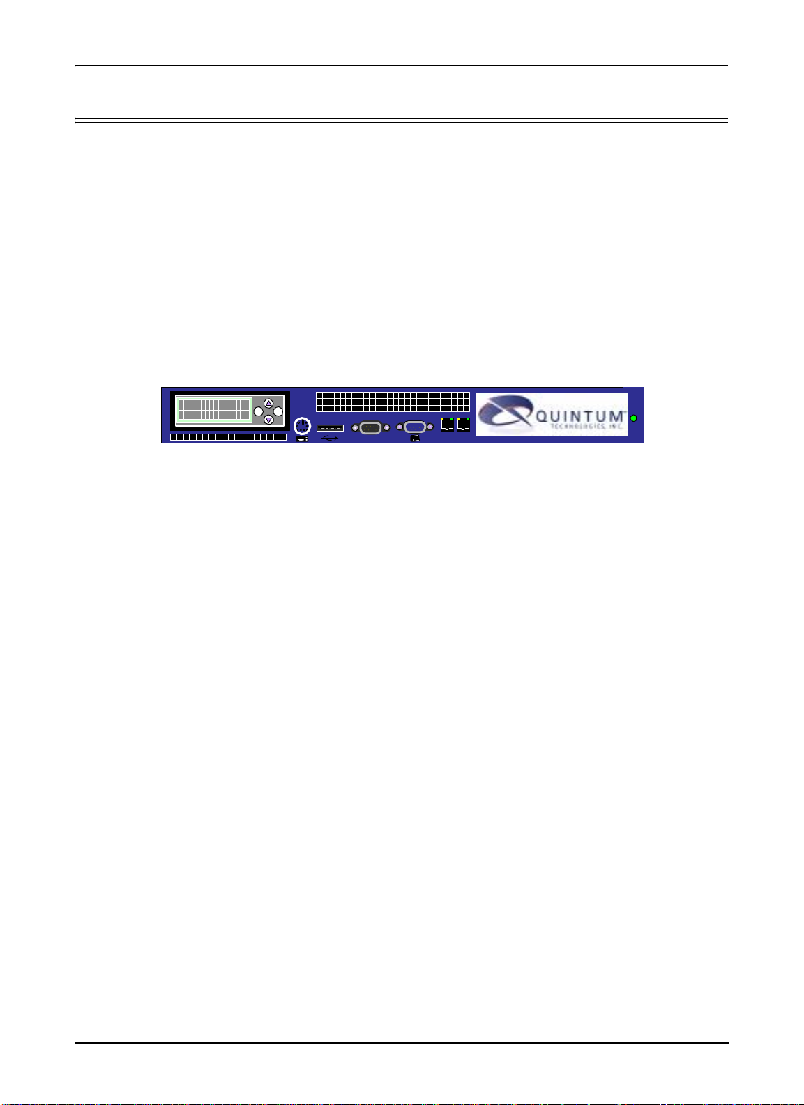
Figure 1-1 Tenor Call Routing Server
ENTER
ESC
10101
LAN 1 LAN 2
The Tenor Call Routing Server is managed by an integrated web-based management system, the Quintum
Routing Server Manager. Through this soft ware, you can configure routing specifications which will be used
through the voice network, as well as configure options such as ingress/egress groups, endpoints, and test
route cases. In addition, you can view custom or pre-defined reports.
1-2 P/N 480-0028-00-00
Page 6

Chapter 1: Overview
Features
System benefits
Designed for medium to large scale converged network deployments, the Call Routing Server lowers operating costs, and increases profits. It supports real-time minimization of termination costs on a call by call basis
and ensures lowest cost call transport while meeting service level agreements.
Routing endpoints may be both ingress and egress endpoints and may be both gateways and gatekeepers; the
centralized routing and management interface allows quick routing changes throughout the network without
individual gateway modifications.
Scalable design
The scalable design allows for the management of mid to large networks. Multiple Call Routing Servers may
be distributed within the voice network for even greater capacity and redundancy. Routing modifications are
immediately reflected throughout the entire voice network without the need for routing modifi cation on indi
vidual gateways.
Flexible Routing/Least Cost Routing
The Call Routing server performs dynamic routing to gateway or trunk group level. There are different types
of routing, such as:
-
• Least Cost Routing (LCR)
• Route Quality. Selects route based on monitored round trip delay and packet loss.
• Answer Seizure Ratio. Selects route based on route quality history (ASR).
• Circuit Routing. Selects route based on best available trunk group (i.e., trunk group on same switch).
• Domain Priority. Selects route to specified carrier trunk group based on ingress number.
• Best Pattern Match. Selects route based on greatest number of dialed digits matched.
• Load Balancing. Automatically selects route to balance load between available trunk groups.
Least Cost Routing (LCR) functionality ensures the lowest cost call transport, while still meeting service level
agreements. The Call Routing Server connects incoming calls to available carriers at the lowest available cost,
by routing calls between IP endpoints or between individual DS0 circuit trunks. The Call Routing Server
employs many methods to achieve Least Cost Routing, including a full route selecti on in which to base calls,
as well as a database of service provider partner data and simplified routing modifications. Any service pro
vider termination rate modifications have immediate impact on call route selection throughout your network.
-
Ingress/Egress capability
Ingress endpoints are devices through which voice traffic enters a given voice network; egress endpoints are
devices through which voice traffic leaves a given voice network.
Egress trunk groups can be logically grouped for routing purposes; an egress group may represent one or more
egress trunk groups. Egress groups may be used for various purposes, but are typically created to logically
separate egress points within the voice network.
Ingress trunk groups and subscribers may be assigned to ingress groups which indicate the criteria used to
route calls. One or more ingress groups may exist in the Routing Server; each group may be configured to
route calls according to a different criteria.
P/N 480-0028-00-00 1-3
Page 7

Chapter 1: Overview
When selecting potential egress routes for each call, the Routing Server’s routing engine selects the appropriate egress routes for a given call after inspecting several criteria dictated by the ingress group associated with
the call.
Access Control
Through an Access Control Directory, configurable through the Routing Server Manager, you are able to configure control over the endpoints which may use voice network services. The Call Routing Server may block
access to the voice network services by certain IP endpoints, or only provide access to voice services from cer
tain IP addresses. Access Control directories enable you to define a profile that indicates the source endpoint
to which calls will be routed.
In the event an endpoint is disallowed access to the voice network, the call will be disconnected with a user
defined cause code; the applicable cause codes are typically defined by ITU-T recommendation, which
defines the standard cause code usage for DSS-1 and SS7 ISUP.
Blocked Number option
T o limit the scope of the service area supported by an ingress group, through the Blocked Number Directories,
you can block certain dialed numbers (DNIS). When a number is dialed which matches an entry in the Block
Number Directory, the call will be rejected. You may use a different blocked number for each of the various
ingress groups within the network.
-
Manual route test capability
A manual test route capability enables you to “test” a call route before actually sending calls over it using the
Routing Server. Through this option, you can simulate a call and a list of successful routes for that specific
call.
Easy installation/access
Installation is complete in three steps: Install hardware, assign IP address to the routing server, and install the
management software, Quintum Routing Server Manager.
An LCD front panel is used to assign an IP address. It’s as simple as entering the applicable IP address and
pressing a button. Once the IP address is assigned, you can install the Routing Server Manager and begin con
figuring the unit.
Integrated Web-based management ease of use
Through the Quintum Routing Server Manager, you can manage your Call Routing Server. The Routing
Server Manager includes the following features:
Simple Windows-based menu tree. Through a Windows-based menu tree, which appears on the left side of
the screen, you can click on the desired menu option and a configuration screen relating to that item will pop
up (if there are sub-menu items available, they will be also listed). From there, you can configure all desired
options and submit the profile. In addition, when you right-click on any menu item, a list of av ailable com
mands, such as Add and Help will be displayed.
-
-
Easy Installation. Once an IP address is assigned to the unit, you can download the Routing Server Manager
from a specific web address. The self-installation process begins immediately and a series of screens will
guide you through the process. A default location is suggested, but you have a choice of where to install the
file. Once the software is installed, you can open the Routing Server Manager and begin configuring/viewing
router files.
1-4 P/N 480-0028-00-00
Page 8

Chapter 1: Overview
Centralized web-management helps lower operating costs. Through the centralized web-based system, you
can easily re-configure routing policy throughout the network.
Call activity generation
Through the Command Line Interface (CLI), you are able to monitor call statistics and view alarm s . Through
the CLI, you can view all call activity for active calls, as well as a call history. In addition, you are able to view
statistics for all endpoints and trunk groups. In addition, you can track the number of active calls in the system.
At any time, through the CLI, you can generate a report that details real-time and historical call details and
event tracing for analysis. Information such as connect time, disconnect time, call duration, and an IP address
are listed for each call. In addition, you can generate a log of all route requests, including rejected requests and
unroutable requests.
Alarm monitoring
Through the Command Line Interface (CLI), at any time you can view a list of all active calls, as well as a history of calls. This information includes the alarm’s ID, time it was generated, IP address, endpoint type, etc.
P/N 480-0028-00-00 1-5
Page 9
Chapter 1: Overview
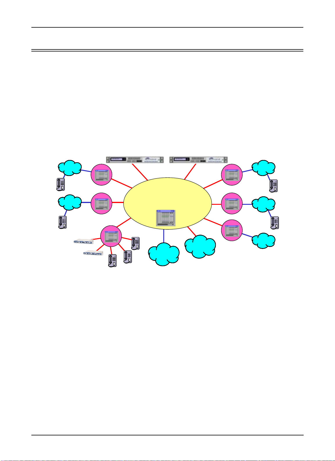
Typical Implementation
Call Routing Server used with Service Provider
The Tenor Call Routing Server offers Service Providers improved profitability and efficiency, including lower
termination costs (least cost routing, time of day routing), management of partners/customers effectively
(source/carrier based routing, IP local loop/subscriber access based routing, network performance monitor
ing), improvement of VoIP network efficiency (through load balancing, better port utilization), and reduction
of operational costs by centralizing (interconnect management, routing policy management, CDR generation,
security/access control).
Service Providers simplify their operations and ability to support various applications. The Tenor Call Routing
Server interconnects with service and application providers, local access services, and calling card services.
-
PSTN
PSTN
Local Access
Provider
Local PoP
Local PoP
Call Routing Server
Next-Gen
Service Provider
Network
Partner
Carriers
Partner
Carriers
VoIP
Carriers
PSTN
Local PoP
PSTN
Local PoP
PSTN
1-6 P/N 480-0028-00-00
Page 10

Chapter 1: Overview
How to use this product guide
What’s included?
This product guide is divided into chapters; each chapter describes a specific topic. The following chapters are
included:
• Chapter 1: Overview: Includes a general overview of the product, including a description of how our
products fit into the VoIP network.
• Chapter 2: Hardware Installation. Lists and describes all components, including all hardware and
cables. Describes how to install the product, including power and ethernet connections.
• Chapter 3:Using the LCD Front Panel/Setting IP Address. Describes how to use the LCD front panel to
configure an IP address.
• Chapter 4: Getting Started via Quintum Routing Server Manager. Describes how to access the Quintum
Routing Server Manager for configuration.
• Chapter 5: Configure via Command Line Interface (CLI). Describes the CLI and how to configure the
Routing Server.
Product Guide Conventions
Certain typographical conventions are used throughout this product guide. See below.
• All commands you enter via keystrokes appear in bold (e.g., Press Enter or Press Ctrl-I).
• All text commands you enter via Telnet session or command line typing appear in italics (e.g., type
active).
• There are three types of special text that are designed to reveal supplemental information: Note, Warning, and Caution. See below.
NOTE provides additional, helpful information. This information may tell you how to do a certain task
or just be a reminder for how-to’s given in previous sections.
A WARNING provides information about how to avoid harm to your VoIP equipment or other equipment (i.e., Do not stack more than 4 units together).
A CAUTION provides information about how to avoid injury to yourself or to others (i.e., Do not install
the equipment during a lightning storm).
P/N 480-0028-00-00 1-7
Page 11
Chapter 1: Overview
Finding Help
There are two help systems in which you can gain help when using the Routing Server Manager: a field Help
button from each screen or online help.
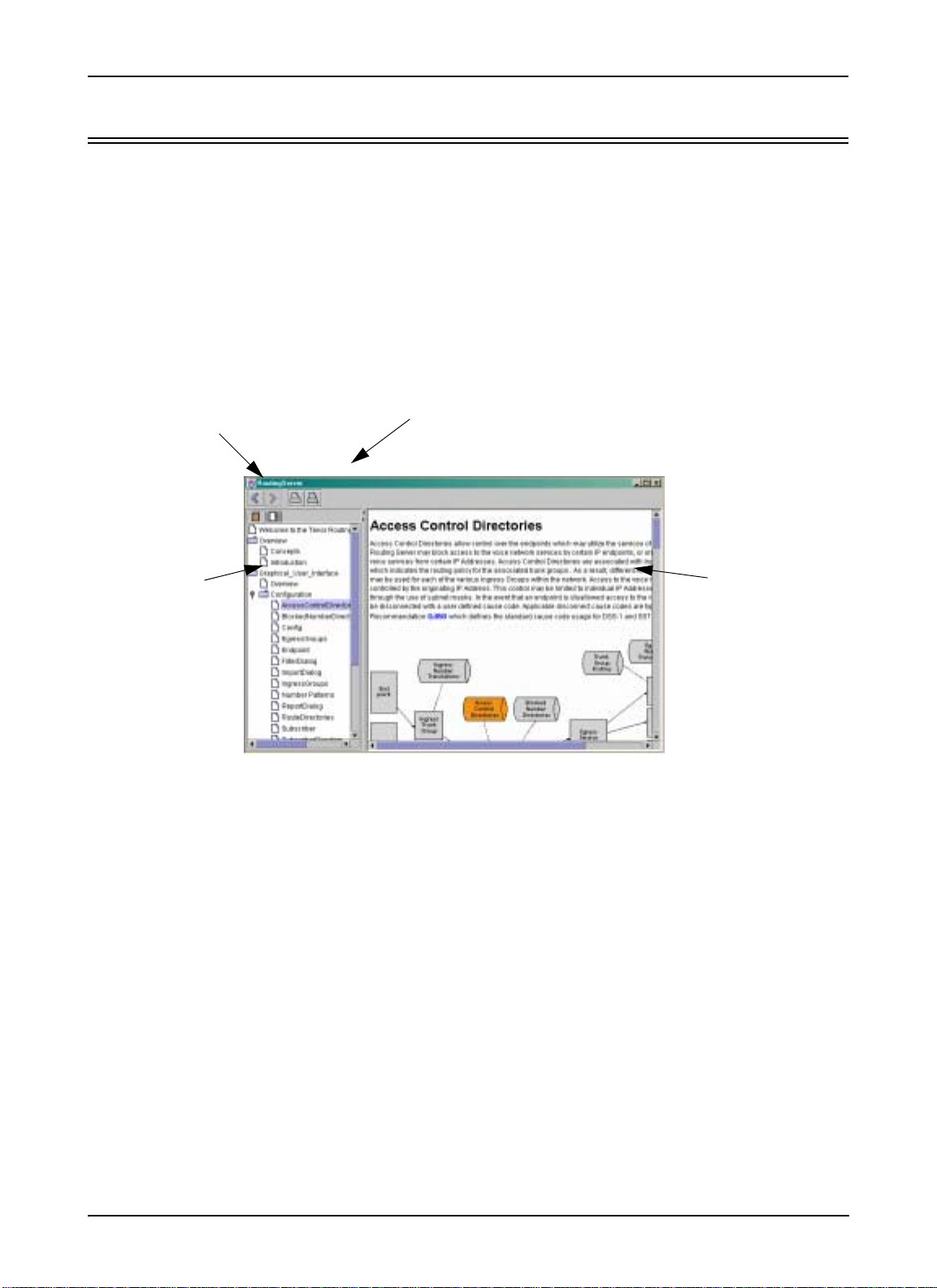
Online Help
A complete, online help system is available at your fingertips. To reach Help, click on the Question mark icon
from the main tool bar at the top of the screen. The online help system will be displayed. Click on the desired
icon for which you would like help. Information about that field will be displayed in the main panel. Refer to
the online help for all field descriptions.
Figure 1-2 Online Help
Print/Print Setup
Move to previous/next screen
Click on an
icon for help
Main Help panel
includes descriptions
Field-specific help
You can obtain help for each field on each screen in the Routing Server Manager. From any screen, click on
the Help button (appears on the bottom of the screen) and click in the field in which you would like help. Help
for that field will pop up (as part of the complete online Help system) in the main panel.
Product Guide
Refer to this Product Guide for help. The Table of Contents and Index tells you where to find information easily.
1-8 P/N 480-0028-00-00
Page 12

Chapter 2: Hardware Installation
This chapter gives you the Network Application Server hardware platform used to run the Tenor Call Routing
Server.
Specifically, the following topics are covered:
! Front/Rear panel description
! Cable descriptions
! Installation procedure
P/N 480-0028-00-00 2-1
Page 13
Chapter 2: Hardware Installation
Hardware description
Front Panel
The Tenor Call Routing Server is a stackable/rack mountable device which connects to a PC console and
Ethernet network.
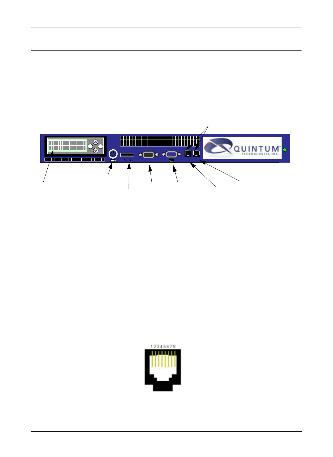
The unit’s front panel includes connection jacks, LEDs, etc.
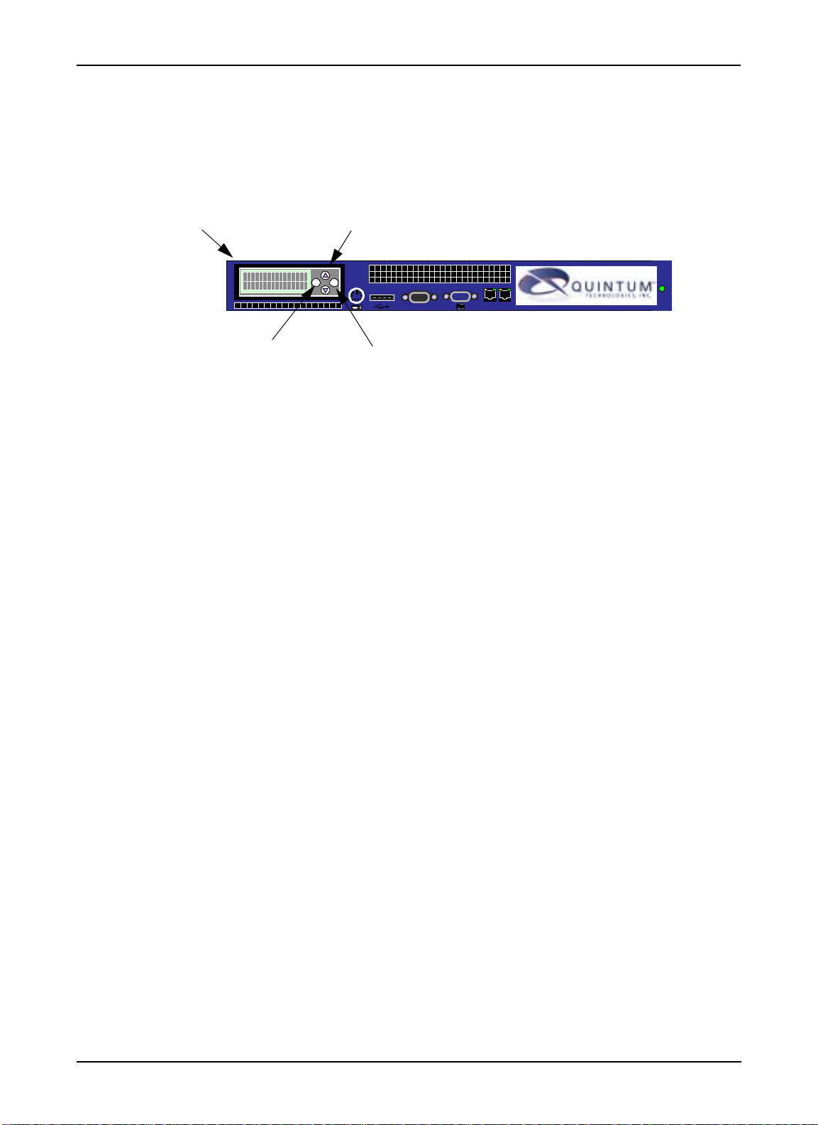
Figure 2-1 Routing Server - front panel
LAN Port LEDs
ENTER
ESC
10101
LAN 1 LAN 2
PS2/Keyboard
LCD Screen
Console
Port
VGA Port
LAN port1USB port
LAN Port 2
LCD Screen. This screen is used for assigning an IP address to a Call Routing Server and variou s othe r status
functions. The LCD has four buttons: Up arrow, Down arrow, escape, and enter. The Up and Down arrows
enable you to enter each number of the IP address. Pressing ENTER confirms the numbers in the database;
pressing ESC will undo the last action. See
Chapter 3: Using the LCD front panel/Setting IP address for more
information.
PS2 Keyboard. Not used.
USB Port. Not used.
Console Port. Not used.
VGA Port. Not used.
LAN 1 port. Ethernet port provides an RJ-45 jack for individual connection to a 10/100 Ethernet LAN switch
or hub via RJ-45 cable. The Ethernet port enables connection between an Ethernet hub/switch and the Call
Routing Server. This connection is required for installation.
Figure 2-1 10/100 Ethernet Port Pin Order
2-2 P/N 480-0028-00-00
Page 14

Chapter 2: Hardware Installation
Table 2-1 Input/Output 10/100 Ethernet
Pin # Signal Definition Color
1 TX + Transmit Data White w/orange
2 TX - Transmit Data Orange
3 RX + Receive Data White w/green
4 RSVD Reserved Blue
5 RSVD Reserved White w/blue
6 RX - Receive Data Green
7 RSVD Reserved White w/Brown
8 RSVD Reserved Brown
LAN 2 Port. Reserved for future use.
LAN Port 1 LEDs. The LAN port LEDs (for 10/100) display the health of the Ethernet connection. There are
two LEDs; see below for a description.
Figure 2-2 LAN Port 1: LED Definitions
LED Left LED Right LED Description
LAN Port 1 Unlit Unlit Network link not established.
Off Green 10 Mbps Ethernet Indication.
The T enor unit detects the 10 Mbps Ethernet
link integrity signal indicating normal con
dition.
Off Blinking
Green
Yellow Off 100 Mbps Ethernet Indication.
Blink Yellow Off 100 Mbps Ethernet Activity.
10 Mbps Ethernet Activity.
Detects activity on the 10 Mbps Ethernet
link integrity signal.
The Tenor unit detects the 100 Mbps Ethernet link integrity signal, indicating normal
condition.
On: Detects activity on the 100 Mbps Ethernet link integrity signal.
-
P/N 480-0028-00-00 2-3
Page 15
Chapter 2: Hardware Installation
Front LCD Screen
Through the Front LCD Panel, you can view and assign IP part numbers, as well as view software version
numbers and display the general status of the Call Routing Server.
Figure 2-3 LCD Display Components
LCD
Up/Down Arrows
Display
ENTER
ESC
LAN 1 LAN 2
Enter
10101
Esc
LCD Display Area. Displays menu options and an area in which to enter data.
UP/Down Arrows. Used to move between menu options, and entering numeric data.
ENTER. Used to save data to the Routing Server.
ESC. Used to cancel the current function, or move back to the previous menu item.
P/N 480-0028-00-00 2-4
Page 16

Rear Panel
Figure 2-4 Routing Server - rear panel
Power switch. Switch to turn the power on and off.
Power cord outlet. Cord to plug into an AC outlet for power.
Fan. Used for cooling purposes.
Chapter 2: Hardware Installation
0
1
Power Switch
Power Cord
Fan
Outlet
P/N 480-0028-00-00 2-5
Page 17

Chapter 2: Hardware Installation
Cables
The cables listed below are required to connect the Call Routing Server to various interfaces.
Cable Usage
RJ-45 to RJ-45 CAT 5 Cable Connection to Ethernet Port Yes
Country approved AC Power Supply
cord. Supplied with Routing Server
Connection to AC power jack. Yes
Supplied with Routing
Server
P/N 480-0028-00-00 2-6
Page 18

Chapter 2: Hardware Installation
Install hardware
Before you begin
Once the Call Routing Server is in place, you will need to make only the physical connection between the unit
and the Ethernet hub/switch, as well as plug the unit into an AC outlet. Once connected, you can configure the
unit via Quintum Routing Server Manager software.
System Requirements
Inspect package contents
Before you install the hardware, ensure the following components are included in your shipment.
• Tenor Call Routing Server and mounting hardware
• 1 AC Power Cable
• RJ-45 Ethernet LAN Cable (one or two depending upon your custom configuration)
• CD ROM containing User Documentation
If a listed component is not included in your package, contact your customer service representative.
Pre-installation guidelines
• Inside parts have hazardous voltages. If the cover is removed, your warranty will be void.
• Do not connect equipment in wet conditions or during a lightning storm.
• The area must not exceed any of the environmental limits outlined in Appendix A: Technical Specifica-
tions.
Position the unit
The unit can be installed on a flat surface (i.e., tabletop) or mounted within a rack.
Tabletop Install. The unit can be located on any sturdy, flat surface. If necessary, you can stack up to four
units together. Before locating the unit on a tabletop, read the location guidelines that follow.
WARNING: If installing on a tabletop or any other flat surface, we recommend that you stack no more than
four units together.
Pre-Installation Guidelines
• The surface must be sturdy.
• Avoid exposing the unit to excessive vibrations.
• Keep the unit away from wet or dusty areas.
• The area must not exceed any of the environmental limits outlined in Appendix A: Technical Specifica-
tions.
• Leave at least 3” clearance surrounding the unit.
• Do not cover any of the ventilation holes.
P/N 480-0028-00-00 2-7
Page 19

Chapter 2: Hardware Installation
Locate the unit on a tabletop as follows:
1. Place the unit on a desk, tabletop, or any flat, solid surface.
2. Ensure the unit will not slip or fall from the surface.
3. Ensure the power cord within reach of the power outlet.
Rack Install. The unit can be located in a standard 19” rack. Mounting brackets are attached to the unit; the
rack is not included with your system. (See the documentation that comes with your rack for detailed installa
tion instructions.)
Pre Installation Guidelines
• The maximum recommended ambient temperature is 40º C (104º F). Internal rack temperature should be
considered for safe operation.
• Do not restrict airflow vents when installing the unit in the rack.
• Mechanical loading of rack should be considered so that the rack remains stable and unlikely to tip over.
• Consider the overall loading of the branch circuit before installing any equipment in a rack environment.
• Ensure that a reliable earthing path is maintained in a rack system. This unit is intended to be connected
to earth ground.
-
Required Materials
• 19” rack (not included with system)
• #10 - 32 x 5/8 screws (qty: 4) (included with system)
• #10 - 32 clip nuts (qty: 4) (included with system)
• 6 mm x 20 mm screws (qty 4) (included with system)
• 6 mm clip nuts (qty 4) (included with system)
• screws as required by your rack manufacturer
Install the chassis in a rack as follows:
1. Choose a position for the chassis within the rack.
WARNING: If the Call Routing Server is the only equipment installed in the rack, ensure it is level with
the rack to avoid the rack from becoming unbalanced. Ensure the equipment is secured with
four screws.
1. Align the chassis mounting brackets flush with the rack’s mounting holes (see Figure 2-5) and follow the
vendor specific instructions for rack installation. The screws provided require a Phillips #2 screwdriver.
2. Ensure the chassis is secured firmly to the rack.
P/N 480-0028-00-00 2-8
Page 20
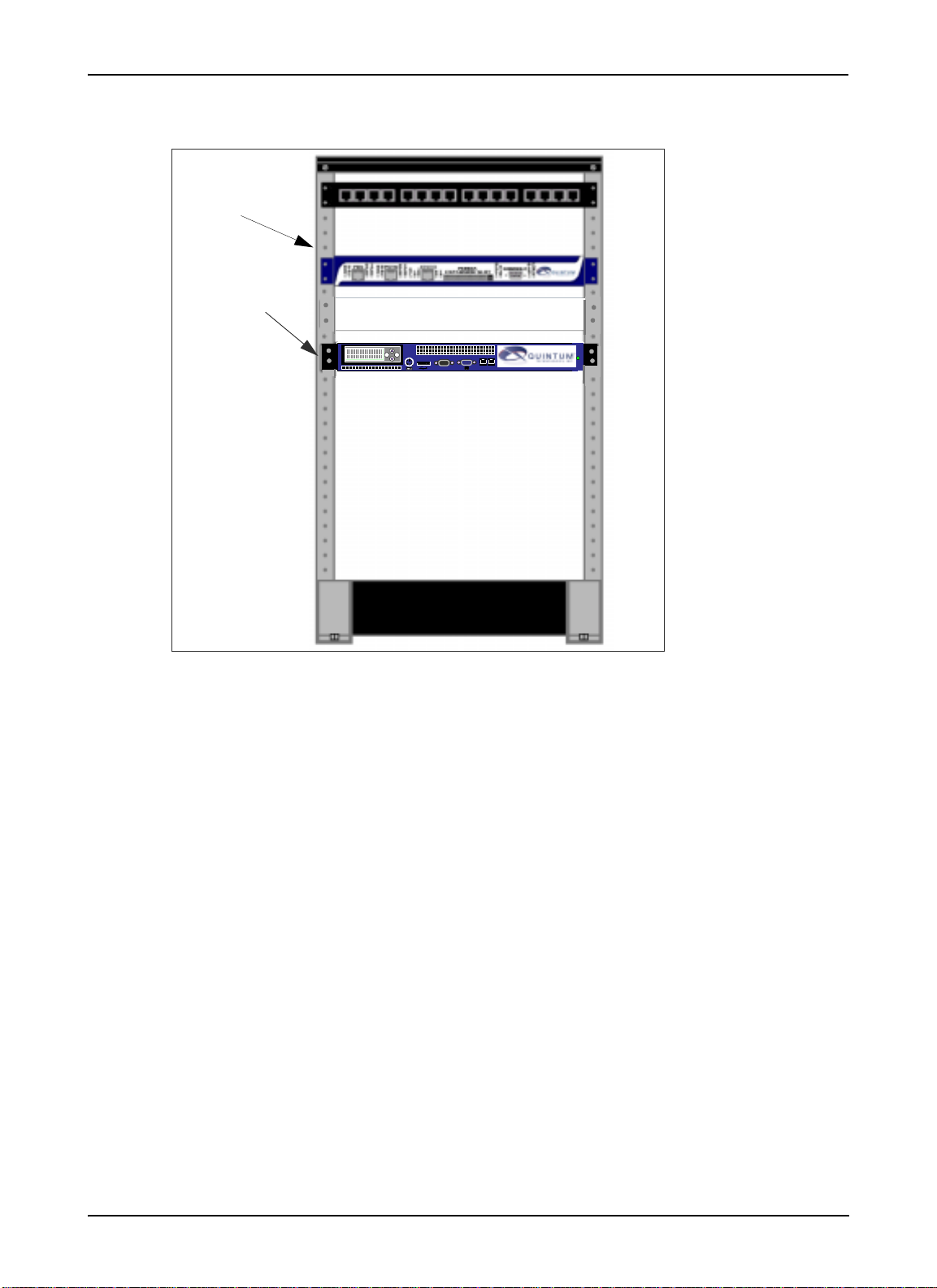
Rack
Mounting
Holes
Call Routing
Server
Figure 2-5 Rack Installation
ENTER
ESC
LAN 1 LAN 2
10101
Chapter 2: Hardware Installation
P/N 480-0028-00-00 2-9
Page 21
Chapter 2: Hardware Installation
Connect the unit
The following steps are required to fully connect the Call Routing Server:
• Connect to Ethernet LAN port
• Power up the system
Connect to Ethernet LAN 10/100 hub/switch
NOTE: Connection to one Ethernet hub/switch is required for initial installation.
You can use these instructions for general connectio n only. The Ethernet hub/switch documentation should
provide specific instructions for connection to another device, such as the Call Routing Server.
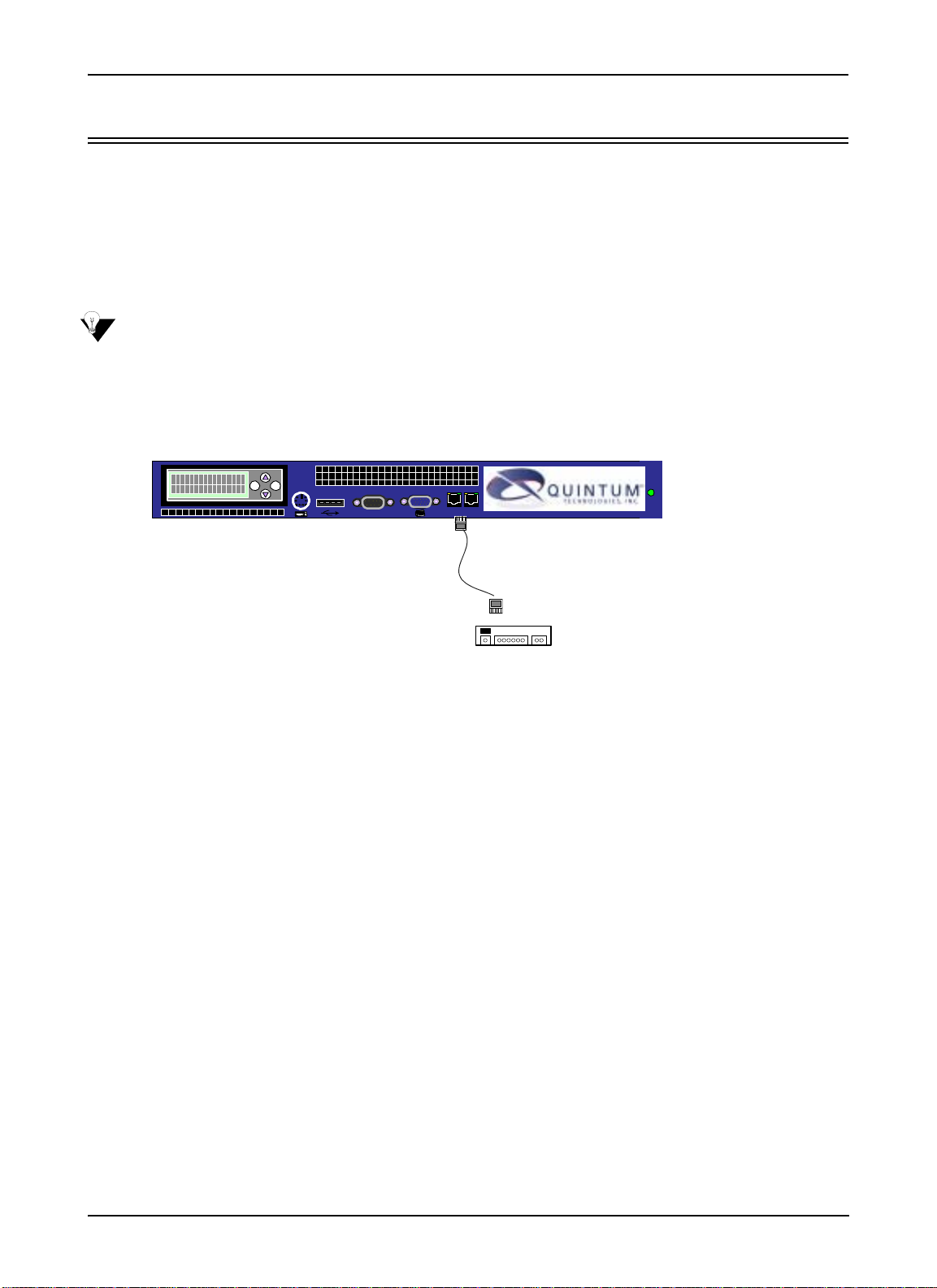
Figure 2-6 Connect to Ethernet Hub/Switch
ENTER
ESC
10101
LAN 1 LAN 2
LAN 1
for 10/100
connection
Ethernet Hub/Switch
1. Insert one end of the RJ-45 cable into the unit’s port labeled LAN 1 port. (LAN 2 port is reserved for future
use.
2. Insert the other end of the RJ-45 connector into an appropriate Ethernet port. See your Ethernet documentation port requirements for connection specifics. (If another cable or adaptor is required, see Chapter 2:
Hardware Components for connector pinout information.)
P/N 480-0028-00-00 2-10
Page 22

Chapter 2: Hardware Installation
Power up the system
Once you have all cables connected properly, you are ready to turn the system on as follows:
Power Cord Outlet
0
1
1. Insert the appropriate end of the power cord into the power cord outlet on the rear of the Tenor Call Routing Server.
2. Plug the other end of the power into an AC outlet.
3. Locate the on/off switch on the back of the unit and push the switch to On.
4. The Call Routing Server is shipped in a state that requires you to assign the local IP information. See the
following section Assign IP address.
Assign IP Address
Before you can configure Tenor Call Routing Server you need to assign a valid IP address. See Chapter 3:
Using the LCD front panel/Setting IP address for information about assigning an IP address.
P/N 480-0028-00-00 2-11
Page 23

Chapter 3: Using the LCD front panel/Set-
ting IP address
This chapter explains how to use the T enor Call Routing Server’s LCD front panel to configure an IP address.
Specifically, the following topics are covered:
! Configure IP via front panel and
! View statistics via front panel
P/N 480-0028-00-00 3-1
Page 24

Chapter 3: Using the LCD front panel/Setting IP address
Assign IP Address
Before you can configure T enor Call Routing Server , you need to assign a valid IP address; the default factory
IP is 0.0.0.0. An IP address is a 32 bit (up to 12 numeric characters) address used to identify each network
device in the TCP/IP network. If the chassis does not have an IP address, data will not be able to be sent to or
from the chassis.
There are two ways to assign an IP address: through the unit’s serial port or through the LCD panel on the
front of the unit. See below for instructions.
Assign IP address via Front LCD Panel
When you turn on the unit, you are able to set the LAN 1 IP, Subnet Mask, and Gateway IP through the LCD
screen.
Configure the information as follows:
The LAN 2 is reserved for future use.
Figure 3-1 Assign IP Address via LCD Display
LCD
Up/Down Arrows
Display
ENTER
ESC
LAN 1 LAN 2
Esc
10101
Enter
When you first turn on the unit, the Quintum Call Routing Server screen wi ll be displ ayed.
1. To set LAN 1 IP, click on the up arrow through the menu items until you reach “Routing Server Change
LAN 1 IP” and press ENTER.
2. Enter the LAN 1 IP address. For each number of the IP address, use the Up and Down arrows to cycle
through the numbers 0-9 and the period (.). When you reach the desired number or period, press on the
ENTER button. For example, to enter IP address 192.168.20.142: press the Up arrow until you reach 1
and press ENTER, press the Down arrow until you reach 9 and press ENTER, press the Up arrow until
you reach 2 and press ENTER, etc. Once all the digits are enter, press ENTER for the IP address to be
entered into the database. The “Enter Subnet Mask” menu option will appear automatically.
3. Enter the Subnet Mask IP (the same way as you entered LAN1 IP) and press ENTER.
4. Press the Up arrow until you reach the “Change GW IP” menu option, and press ENTER. The “Enter
Gateway IP” screen will be displayed.
5. Enter the Gateway IP address (for using the arrows to set the IP, use the same directions as setting LAN 1
IP) and press ENTER.
Once the IP information has been set, you are ready to configure the Call Routing Server via the network. See
Chapter 4: Getting Started via Quintum Routing Server Manager and Chapter 5: Configure via Command
Line Interface (CLI).)
3-2 P/N 480-0028-00-00
Page 25

Chapter 3: Using the LCD front panel/
Display Status/IP/Software Version via LCD Panel
Through the Front LCD Panel, you can view and assign IP part numbers, as well as view software version
numbers and display the general status of the Call Routing Server.
Figure 3-2 LCD Display Components
LCD
Up/Down Arrows
Display
ENTER
ESC
LAN 1 LAN 2
Esc
10101
Enter
Through the LCD panel, you can view the status of the Call Routing Server, including Calls, Calls Per Second,
and Alarm information. In addition, you can view the number currently configured for LAN 1 IP , Gateway IP,
and Software Revision.
Display general status information
1. To view the Routing Server statistics, use the up arrow to access the “Routing Server Display Status” menu
item. Press ENTER. The statistics will be displayed as follows: :
Calls CPS Alrm
110 10 2
Calls: Displays total number of calls in the network.
CPS: Average network load expressed as calls per second.
Alarm: Number of alarms in the system.
2. To display the LAN 1 IP or Gateway IP, use the Up arrow to access the “Routing Server Display LAN1
IP”, or “Routing Server Display GW IP” menu option. Press ENTER. The applicable IP address will be
displayed.
3. To display the software version number, use the Up arrow to access the “Display Software Rev” menu
option. Press ENTER. The revision number of the current software running on the Routing Server will be
displayed.
4. Press Esc to move to the previous menu option.
P/N 480-0028-00-00 3-3
Page 26

Chapter 3: Using the LCD front panel/
Change IP (for LAN1 or Gateway)
Through the LCD panel, you can change the IP address for LAN 1 or the Gateway.
1. To change the IP for LAN1 or Gateway , use the Up arrow to access the “Routing Server Change LAN1 IP”
or “Routing Server Change GW IP” menu option. Press ENTER. The corresponding menu option will be
displayed.
2. Enter the applicable IP address as follows:
3. For each number of the IP address, use the Up and Down arrows to cycle through the numbers 0-9 and the
period (.). When you reach the desired number or period, press on the ENTER button. For example, to
enter IP address 192.168.20.142: press the Up arrow until you reach 1 and press ENTER, press the Down
arrow until you reach 9 and press ENTER, press the Up arrow until you reach 2 and press ENTER, etc.
Once all the digits are enter, press ENTER for the IP address to be entered into the database. The “Enter
Subnet Mask” menu option will appear automatically.
4. Once all the digits are entered, press ENTER for the IP address to be entered into the database.
P/N 480-0028-00-00 3-4
Page 27

Chapter 4: Getting Started via Quintum
Routing Server Manager
This chapter tells you how to install the Quintum Routing Server Manager You will also find system requirements for installation, as well as the actual installation procedure and information about moving around within
the Ten or Routin g Server Manager.
Specifically, the following topics are covered:
! System requirements
! Installation procedure
! Login the Quintum Routing Server Manager
! How to use the software
! Navigating through the screens
P/N 480-0028-00-00 4-1
Page 28

Chapter 4: Getting Started via Quintum Routing Server Manager
What is the Quintum Routing Server Manager?
Through a web-based GUI, the Quintum Routing Server Manager enables you to perform all configuration
functions for the Tenor Call Routing Server. For example, you can configure data for all configuration options,
such as number directories, trunk groups, and endpoints.
System Requirements
The following are required to install the Quintum Routing Server Manager software on your PC:
• Pentium III 800MHz processor (minimum)
• 256 MB Memory
• 128 MB free hard disk
• Internet connection
• Microsoft® Windows 2000 or Microsoft® Windows XP
Installation
NOTE: At any time during the installation process, you can click on Cancel to cancel the installation. If
necessary, to install the software, follow the procedure for Add/Remove Programs via
Microsoft® Windows.
Install the software on your PC as follows:
1. Using Internet Explorer, type http:// (followed by the IP address of the applicable Routing Server unit and
8080 as the port number. For example, type http://192.170.2.24:8080. A login screen will be displayed.
2. For Login, the default is admin; for password, the default is admin.
3. The Quintum Router Server Manager screen will be displayed. Click on Start Installer for Windows.
The installation process will begin (To cancel the installation process at any time, click on Cancel).
4. Choose a directory in which to install the software (the default is C:\Program Files\Quintum Routing
Server Manager). You will be guided through the rest of the installation process.
5. When installation is complete, click on Done.
4-2 P/N 480-0028-00-00
Page 29

Chapter 4: Getting Started via Quintum Routing Server Manager
Login Quintum Routing Server Manager
After installing the Quintum Routing Server Manager software, you are ready to login and get started with the
Routing Server.
1. Access the Quintum Routing Server Manager menu item (located in the area in which you specified during
installation). For example, click on Start > Programs >Quintum Routing Server Manager>RoutingConfig.
The Specify Routing Server IP Address window will be displayed.
2. Enter the Routing Server IP address of the Call Routing Server in which you would like to configure.
3. Enter the Routing Server Port, 8080. The Specify Login and Password screen will be displayed.
4. Enter login and password (default entries: admin). Click on OK. The Quintum Routing Server Manager
will open.
You are now ready to configure a Quintum Routing Server. See the rest of this chapter for more information
about moving around the manager, using screens, etc. To learn how to configure the unit, see
Screens, later in this chapter.
Configure
P/N 480-0028-00-00 4-3
Page 30

Chapter 4: Getting Started via Quintum Routing Server Manager
Getting started with Quintum Routing Server Manager
Main Window
The main window is the central point of the Routing Server Manager. From there, you can click on icons to
see other windows, as well as configure fields for different windows. Each component is described below.
Figure 4-1 Main Window
Drop Down Menus
Display Area
Menu
Tree
Common Buttons
P/N 480-0028-00-00 4-4
Page 31

Chapter 4: Getting Started via Quintum Routing Server Manager
Drop Down Menus
Drop down menus enable you to perform several different functions within the system, such as connecting to
a new IP address to importing/exporting files.
Figure 4-2 Drop Down menu
Drop Down
Menu
Sample
Definitions for all drop down menu options are listed below.
File
• Connect. Enables you to select a new IP address in which to connect.
• Activate Changes. Saves the configuration changes to the database.
• Password. Enables you to set a password upon login.
• Exit. Exits the system.
Action
• Report. Enables you to create a pre-defined or customized report. When you select this option, you will
be brought through a mini-wizard to define the report.
• Test Route. Enables you to configure a test route, which simulates the routing of an actual call before the
call goes through. The Routing Server will then list destinations available for that call.
• Import File to Table. Imports a file to a database table. For example, you can import routing informa-
tion provided by a service provider.
• Export Table to HTML. Exports routing table to a report format in HTML format.
• Export Table to PDF. Exports routing table to a report format in PDF format.
Display Area
The display window is the main configuration section of the Routing Server Manager. Once you click on a
desired icon from the menu tree, the corresponding configuration window appears in the display area.
P/N 480-0028-00-00 4-5
Page 32

Chapter 4: Getting Started via Quintum Routing Server Manager
Menu Tree
Each menu tree item represents a configuration window available in the main display area. If a menu tree
option is “label” only; the menu tree will expand to offer the sub-menu options. A “+” to the left of the option
indicates the immediate menu tree can be expanded to display sub-menu options; a “-” to the left of the option
indicates it is at the lowest level of available options and cannot be expanded.
Figure 4-3 Menu tree
Click on ‘+’ to expand;
Click on ‘-’ to close menu
Also, when you right-click on each menu tree item, a list of commands will appear.
The type of menu tree item will determine which commands are listed. Not all commands will be listed under
each item. For example, for those menu options that can be added (i.e., IP Dial Plan), the Add option will
appear; under those menu options that cannot be added, the Add option will not appear. All of the possible
commands are described below .
• Refresh. Refreshes the screen.
• Add. Adds a new sub-menu option for the selected menu item.
• Delete. Deletes a sub-menu option from the selected menu item.
• Help. Accesses the help for that selected menu option.
P/N 480-0028-00-00 4-6
Page 33

Chapter 4: Getting Started via Quintum Routing Server Manager
Common Screen Buttons
This groups of buttons is available from each screen. The main buttons, available in the lower part of the display window, are available from each screen.
Figure 4-4 Common Screen Buttons
Common Screen Buttons
Use the following information as a guide:
• Confirm/Ok. Confirms the information you configured on the screen but does not save it to a permanent
database. A dialog box will appear to confirm. Click on OK to confirm (to cancel, click on Cancel).
• Cancel. Cancels the information you entered on the screen.
• Refresh. Clears the screen back to the default values. If you are on a different tabbed panel, it will bring
you back to the top level window. You can also perform a refresh by right-clicking on the desired menu
option and selecting Refresh from the drop down menu.
• Help. When you click on Help and the desired fields, help will pop up on the screen.
Screen Conventions
The Routing Server Manager system requires you to enter information or select field entries from various field
types. These field types are as follows:
Edit box. The edit box is a field which enables you to enter alphanumeric characters. The maximum number
of digits/letters you can enter depends upon the field definition.
P/N 480-0028-00-00 4-7
Page 34

Chapter 4: Getting Started via Quintum Routing Server Manager
Figure 4-5 Edit Box sample
Edit Box
Radio button. Radio buttons enable you to click on the desired field entry from a list of choices. A checked
radio button indicates the option is enabled; unchecked indicates the option is disabled.
Figure 4-6 Radio Button sample
Radio Button
Drop down list box. The drop down list box is a list of entries displayed when you click on the arrow to the
immediate right of the box. To select an entry, click on any item from the drop down list and it will appear as
the selection.
Figure 4-7 Drop Down List sample
Drop Down
List Box
P/N 480-0028-00-00 4-8
Page 35

Chapter 4: Getting Started via Quintum Routing Server Manager
Navigating through the screens
There are several ways to navigate through the screens: Menu Tree, Too l Ba r, and Tabbed Panels. See below
for a description of each:
• Menu Tree. To reach any screen, click on the desired menu item from the menu tree and the applicable
configuration window will be displayed.
• Navigation Buttons. Two navigation buttons on the tool bar enable you to navigate from one screen to
the next, from the previous screen to the next and vice versa.
• Tabbed Panel. If the screen has more than one layer, it is arranged as tabbed panels, each panel has a
label that indicates its contents. Click on the desired panel in which you can configure.
Connect to a different Routing Server
NOTE: The configuration instructions in this chapter assume the T enor Intelligent Router Manager soft-
ware is installed and it is connected to an IP (via LCD panel, see Chapter 3: Using the LCD front
panel/Setting IP address).
If you are not connected to an IP address, or would like to change the IP address to which you are connected,
using the following instructions:
1. Click on File> Connect. The Specify Routing Server IP Address screen will be displayed.
Figure 4-8 Specify Routing Server IP Address screen
2. Click on the down arrow to choose Routing Server IP Address. Enter the desired IP address and click Ok.
The Confirm Login and Password screen will be displayed.
3. Enter the login ID (default login: admin).
4. Enter the login password (default password: admin).
P/N 480-0028-00-00 4-9
Page 36

Chapter 4: Getting Started via Quintum Routing Server Manager
5. If desired, click on “Remember my Password.”
6. Click on Ok. The Routing Server Manager will connect to the Routing Server, the database will be loaded
and the main configuration screens will be displayed.
Change Password
At any time, you can change the password on the unit; the default password is admin. Change the password as
follows:
1. Click on File> Password. The Password Change screen will be displayed.
Figure 4-9 Password Change screen
2. Enter a login name, old password, new password, and enter the new password again to confirm.
3. If desired, click on “Remember my Password.”
4. Click Ok. The new password will be defined.
P/N 480-0028-00-00 4-10
Page 37

Chapter 4: Getting Started via Quintum Routing Server Manager
Configure Screens
Once you have a basic idea about how to move around within the software, you are ready to configure the
screens. All screen information, explaining all field definitions, are included in the software’s online help.
P/N 480-0028-00-00 4-11
Page 38

Chapter 5: Configure via Command Line
Interface (CLI)
This chapter tells you how to configure the Routing Server via Command Line Interface (CLI). Specifically,
the following topics are covered:
! Access the Command Line Interface (CLI)
! Configure via CLI
P/N 480-0028-00-00 5-1
Page 39

Chapter 5: Configure via Command Line Interface (CLI)
Configure
Through the Command Line Interface (CLI), you are able to configure items such as gateway, ethernet, and
NTP IP addresses, RADIUS information, as well as perform maintenance procedures. There are several differ
ent areas you are able to configure via CLI:
Configuration. Through the configuration options, you are able to set IP addresses, such as the ethernet port,
gateway and NTP server. In addition, you can configure RADIUS information.
Maintenance. Through the maintenance options, you are able to set Call Routing Server options including
backing up data, restoring data, and setting the operating state of the unit.
Monitoring. Through the monitoring options, you are able to view the event log, as well as the version number of the Routing Manager, status, and time.
Licenses. Through the license options, you can view the unit’s current license, as well as update the current
license.
Misc. The miscellaneous options enables you to logout of the system and clear the screen.
See the following sections for accessing the CLI; a description of each command follows.
-
Access CLI
Once the Tenor has been initially configured with it's IP address information (see Chapter 3: Using the LCD
front panel/Setting IP address) and connected to your network, you can connect to the CLI through a standard
SSH session from any PC on your IP network.
Most Unix™ and Linux™ operating systems come with an ssh client such as openssh. For Windows, there are
many ssh clients available. The two most popular are Putty and SecureCRT. See below.
• Putty (freeware): http://www.chiark.greenend.org.uk/~sgtatham/putty/
• SecureCRT®: http://www.vandyke.com/
Use your SSH client to establish an SSH session using the assigned IP address of your Routing Server as follows:
1. Enter a login name. The login name is admin.
2. Enter a password. The default password is admin.
The Routing Server prompt will be displayed. At any time, type ? or help to display a list of valid CLI commands. The available commands, including field descriptions, are contained within the following pages.
5-2 P/N 480-0028-00-00
Page 40

Chapter 5: Configure via Command Line Interface (CLI)
Configuration
ether
Description:
Enables you to configure the Ethernet Port IP Configuration, Ethernet Port IP
Address and Ethernet Port Subnet Mask, as we ll as displays the current Eth er
net Port IP address and Subnet mask already configured.
When the unit is initially shipped, the IP address is set to 0.0.0.0.
Two Ethernet ports are supported: Ether 0: supports 10/00, Ether 1: supports
10/100/1000.
NOTE: Ethernet port 2 is reserved for future use.
-
Cmd Type:
Prompt Level:
Syntax:
Availability:
Examples:
Sample Display:
Guidelines:
Command.
Main Routing Server prompt.
ether {1|2}. Displays ethernet statistics for the given ethernet port.
ether {1|2} ip {ipaddress}. Standard IP address that you enter for the given eth-
ernet port.
ether {1|2} netmask {netmask}. Standard subnet mask that you enter for the
given netmask port.
All Releases of Tenor Routing Server
Routing Server> ether0
Routing Server> ether 1 ip 192.168.8.29 - sets the IP address to 192.168.8.29.
Routing Server> ether 1 netmask 192.168.8.29 - sets the netmask to 192.168.8.29.
Sample for ether0 command:
Ethernet Port 0 Configuration
IP Address : 192.168.2.20
Subnet Mask: 255.255.255.0
To change this IP address initially, see Chapter 3: Using the LCD front panel/
Setting IP address.
P/N 480-0028-00-00 5-3
Page 41

Chapter 5: Configure via Command Line Interface (CLI)
gateway
Description:
Enables you to configure the default IP gateway, as well as display the current
default IP gateway.
When the unit is initially shipped, the IP address is set to 0.0.0.0.
Cmd Type:
Prompt Level:
Syntax:
Availability:
Examples:
Guidelines:
ntpserver
Description:
Command.
Main Routing Server prompt.
gateway. Displays the current default IP gateway.
gateway {ipaddress}. Default gateway IP address that you enter.
All Releases of Tenor Routing Server
Routing Server> gateway. Displays as follows:
Default Gateway IP Address : 192.168.2.1
Routing Server> gateway 192.170.8.20 - sets the default IP gateway to IP address to
192.170.8.20.
To change this IP address initially, Chapter 3: Using the LCD front panel/Setting
IP address.
Enables you to configure the Network Time Protocol (NTP) Server IP address,
as well as display the current NTP Server IP address.
When the unit is initially shipped, the NTPServer IP address is set to 0.0.0.0.
Cmd Type:
Prompt Level:
Syntax:
Availability:
Examples:
Guidelines:
Command.
Main Routing Server prompt.
ntpserver. Displays the current NTP Server IP address.
ntpserver {ipaddress}. Default NTP Server IP address that you enter.
All Releases of Tenor Routing Server
Routing Server> ntpserver. Displays as follows:
Network Time Protocol (NTP) Server: 130.126.24.24
Network Time Protocol (NTP) Server: 140.221.9.20
Routing Server> ntpserver 192.170.8.20 - sets the NTP Server IP address to
192.143.8.20.
To change this IP address initially, you will need to connect to the Tenor via
serial cable.
P/N 480-0028-00-00 5-4
Page 42

Chapter 5: Configure via Command Line Interface (CLI)
passwd
Description:
To prevent unauthorized access to the Routing Server, a password is included
when you first log into the system. The default password is admin. The passwd
command enables you to change the default password.
radius
Cmd Type:
Prompt Level:
Syntax:
Availability:
Guidelines:
Examples:
Description:
Cmd Type:
Prompt Level:
Syntax:
Availability:
Examples:
Command.
Main Routing Server prompt.
passwd {password}. Enter a password.
All Releases of Tenor Routing Server
If there is an error with the password you enter, an error message will be dis-
played.
Routing Server> passwd test1 - the password will be set to test1
Displays RADIUS configuration, including IP port and RADIUS secret.
Command.
Main Routing Server prompt.
radius. The RADIUS IP port and RADIUS secret will be displayed.
All Releases of Tenor Routing Server
Routing Server> radius
Sample Display: Routing Server Radius IP port: 1812
radiusport
Description:
Cmd Type:
Prompt Level:
Syntax:
Availability:
Examples:
Routing Server Radius secret : 123456789
Used to identify the port number for the RADIUS host server.
Command.
Main Routing Server prompt.
radiusport {port}. Configures the RADIUS IP port. Valid entry: 0-65535.
All Releases of Tenor Routing Server
Routing Server> radiusport 1812 - The RADIUS IP port will be set to 1812.
P/N 480-0028-00-00 5-5
Page 43

Chapter 5: Configure via Command Line Interface (CLI)
radiussecret
Description:
Sets the RADIUS key. As a security measure, the sharedsecret enables the
Tenor Routing Server to share encrypted data with the RADIUS server. Some
data is sent to the RADIUS server encrypted, and the RADIUS can then decrypt
it. This value must be identical to the value configured on the RADIUS server.
Cmd Type:
Prompt Level:
Syntax:
Availability:
Examples:
Command.
Main Routing Server prompt.
radiussecret {secret}. Optional, but must match what is configured on the
RADIUS Server. This alphanumeric value can be up to 65 characters in length.
All Releases of Tenor Routing Server
Routing Server> radiussecret 1a2b3c - sets the shared secret of the Tenor to
1a2b3c.
P/N 480-0028-00-00 5-6
Page 44

Chapter 5: Configure via Command Line Interface (CLI)
Maintenance
routeserver
Description:
Sets the operating state of the Routing Server. You can either start, stop, or
restart the Routing Server.
This command is used for debugging purposes. Use care when u sing this
command; the routeserver command should be used for debug purposes
only.
backup
Cmd Type:
Prompt Level:
Syntax:
Availability:
Examples:
Description:
Cmd Type:
Prompt Level:
Syntax:
Command.
Main Routing Server prompt.
routeserver {start|stop|reset}
routserver start. Starts the Routing Server.
routeserver stop. Stops the Routing Server
routeserver reset. Resets the Routing Server; equivalent to performing a rou-
teserver start and subsequent routeserver stop.
All Releases of Tenor Routing Server
Routing Server> routeserverstop - stops the Routing Server.
Performs a backup of Routing Server data, which includes all the information
you configured via CLI or through the Routing Server Manager. The backup file
is stored in the backup directory, under a filename you specify.
Command.
Main Routing Server prompt.
backup {filename.enc}
Availability:
Guidelines:
All Releases of Tenor Routing Server
The backup file will be stored in filename you specify; the default directory is
c:\backup\filename you specify with the .enc extension. An example backup
filename is db.monday.enc. Upon successful backup, a message will be dis
played, “Backup file stored at \backup\db.monday.enc.”
The backup command overwrites the previous backup file.
For backup purposes, we recommend you FTP to the Routing Server and then
FTP the backup file to another machine.
Once the backup is completed, a message will be displayed.
Examples:
Routing Server> backup db.monday.enc - backups the data to c:\backup\db.mon-
day.enc.
P/N 480-0028-00-00 5-7
-
Page 45

Chapter 5: Configure via Command Line Interface (CLI)
restore
Description:
Restores the backup file you created using the backup command.
ping
Cmd Type:
Prompt Level:
Syntax:
Availability:
Guidelines:
Examples:
Description:
Cmd Type:
Command.
Main Routing Server prompt.
restore {filename}
All Releases of Tenor Routing Server
Before issuing a restore command, you must ensure the latest backup file is
stored in the backup directory with the original filename (i.e., /backup/db.mon
day.enc).
The backup file will be restored to the same directory in which the file was created (i.e., \backup\db.monday.enc) Upon successful restore, a message will be
displayed.
Routing Server> restore db.monday.enc - restores the backup file named db.mon-
day.enc.
Ping Command. Used to perform a standard ping test between the Tenor Routing Server and the IP host at the specified IP address.
Command.
-
Prompt Level:
Syntax:
Availability:
Guidelines:
Examples:
Sample Display: Pinging 192.168.1.1 with 32 bytes of data:
Main Routing Server prompt.
ping {ipaddress}
All Releases of Tenor Routing Server
Very useful for testing the IP route between 2 locations.
Routing Server> ping 192.168.1.1 - pings the specified IP address.
Reply from 192.168.1.1: bytes=32 seq=0 time<10mS TTL=255
Reply from 192.168.1.1: bytes=32 seq=1 time<10mS TTL=255
Reply from 192.168.1.1: bytes=32 seq=2 time<10mS TTL=255
Reply from 192.168.1.1: bytes=32 seq=3 time<10mS TTL=255
---- PING Statistics for 192.168.1.1: ---Packets Sent = 4, Received = 4, Lost = 0 (0 Percent Loss)
Approximate round trip times in milli-seconds:
Minimum = 0mS, Maximum = 0mS, Average = 0mS
P/N 480-0028-00-00 5-8
Page 46

Chapter 5: Configure via Command Line Interface (CLI)
Monitoring
The Monitor mode enables you to perform status procedures on the unit. It monitors the unit, which
includes alarm generation and trunk group status.
alarms
Description:
A monitoring command used to display alarm statistics.
Cmd Type:
Prompt Level:
Syntax:
Availability:
Examples:
Sample Display:
Command.
Main Routing Server prompt.
alarms {-h, -a, -l, -o}
alarms -h. Displays help.
alarms -a. Displays active alarms.
alarms -l. Displays alarm history.
alarms -o. Generates log file on server.
All Releases of Tenor Routing Server
Routing Server> alarm -l - an alarm history for the system will be displayed.
alarms -a
Id Time Type Severity IP Address TGId Description
=====================================================================================
1 2003-03-01 03:38:27 2003-03-01 03:38:57 1 1 2 192.168.2.16 9 None Excessive Packet Loss
2 2003-03-01 04:10:44 2003-03-01 04:11:44 1 1 2 192.168.2.16 9 None Excessive Packet Loss
alarms -l
Id Time Clear Time Clear Type Type Severity IP Address TGId Description
=====================================================================================
1 2003-03-01 03:38:27 2003-03-01 03:38:57 1 1 2 192.168.2.16 9 None Excessive Packet Loss
2 2003-03-01 04:10:44 2003-03-01 04:11:44 1 1 2 192.168.2.16 9 None Excessive Packet Loss
3 2003-03-01 04:13:14 2003-03-01 04:15:14 1 1 2 192.168.2.16 9 None Excessive Packet Loss
4 2003-03-05 16:57:54 2003-03-05 17:12:24 1 1 2 192.168.2.16 9 None Excessive Packet Loss
5 2003-03-05 17:22:25 2003-03-05 17:23:25 1 1 2 192.168.2.16 9 None Excessive Packet Loss
P/N 480-0028-00-00 5-9
Page 47

Chapter 5: Configure via Command Line Interface (CLI)
calllog
Description:
Displays the data in the call log.
Cmd Type:
Prompt Level:
Syntax:
Availability:
Examples:
Sample Display:
Command.
Main Routing Server prompt.
calllog {-h, -c, -s, -r, -l, -o)
calllog Displays the data in the call history log.
calllog -h. Displays help.
calllog -c. Clears the calls from the buffer.
calllog -s{IP}. Identifies the call source endpoint IP address. Enter the desired
IP address. Enter a valid IP address.
calllog -d{IP}. Identifies the call destination endpoint IP address. Enter the
desired IP address. Enter a valid IP address.
calllog -r{rec}. Displays specific calllog record by record number. Enter a valid
record number .
calllog -l{num}. Limits the number of displayed log entries displayed on the
screen. A valid entry is 1-5,000.
calllog -o. Writes the screen data to a text file to the \log directory on the
server. You can FTP the file and use any applicable editor to review.
All Releases of Tenor Routing Server
Routing Server> calllog - displays the call log history.
Call History Log Example
Conn Time Disc Time Duration Src IP Dst IP DNIS ANI Disc Code
2003-03-07 14:53:46 2003-03-07 14:54:46 60 192.168.2.169 192.168.2.169 184 72220169 16
2003-03-07 14:53:46 2003-03-07 14:54:46 60 192.168.2.169 192.168.2.169 184 72220169 16
2003-03-07 14:53:45 2003-03-07 14:54:45 60 192.168.2.169 192.168.2.169 184 72220169 16
2003-03-07 14:53:45 2003-03-07 14:54:45 60 192.168.2.169 192.168.2.169 184 72220169 16
2003-03-07 14:53:45 2003-03-07 14:54:45 60 192.168.2.169 192.168.2.169 184 72220169 16
2003-03-07 14:53:46 2003-03-07 14:54:45 59 192.168.2.169 192.168.2.169 184 72220169 16
2003-03-07 14:53:43 2003-03-07 14:54:44 61 192.168.2.169 192.168.2.169 184 72220169 16
P/N 480-0028-00-00 5-10
Page 48

Chapter 5: Configure via Command Line Interface (CLI)
calls
Description:
A monitoring command to displays a log of incoming/outgoing calls, which
includes call source endpoint IP address and destination IP address.
Cmd Type:
Prompt Level:
Syntax:
Availability:
Examples:
Sample Display:
Command.
Main Routing Server prompt.
calls
All Releases of Tenor Routing Server
Routing Server> calls - lists the active calls on the system.
Call Status Example
Id Connect Duration OrigIP OrigTrunk DNIS TermIP TermTrunk
00821286 2003-03-07 14:58:15 99.0 192.168.2.169 10 18472220169 192.168.2.169 0
00821289 2003-03-07 14:58:15 99.0 192.168.2.169 10 18472220169 192.168.2.169 0
00821288 2003-03-07 14:58:15 99.0 192.168.2.169 10 18472220169 192.168.2.169 0
00821291 2003-03-07 14:58:15 99.0 192.168.2.169 10 18472220169 192.168.2.169 0
00821287 2003-03-07 14:58:15 99.0 192.168.2.169 10 18472220169 192.168.2.169 0
00821290 2003-03-07 14:58:15 99.0 192.168.2.169 10 18472220169 192.168.2.169 0
00821292 2003-03-07 14:58:16 98.0 192.168.2.169 10 18472220169 192.168.2.169 0
00821293 2003-03-07 14:58:17 97.0 192.168.2.169 10 18472220169 192.168.2.169 0
00821294 2003-03-07 14:58:19 95.0 192.168.2.169 10 18472220169 192.168.2.169 0
Number of Active Calls: 9
P/N 480-0028-00-00 5-11
Page 49

Chapter 5: Configure via Command Line Interface (CLI)
ipstats
Description:
Displays IP QOS statistics (roundtrip) for each endpoint.
loglevel
Cmd Type:
Prompt Level:
Syntax:
Availability:
Examples:
Sample Display:
Description:
Cmd Type:
Prompt Level:
Syntax:
Command.
Main Routing Server prompt.
ipstats -i{id}. Displays the specific endpoint IP QOS his tory. Enter the specific
ID.
All Releases of Tenor Routing Server
Routing Server> ipstats -i1 - displays the QOS statistics for the specific endpoint IP.
Id IP Address % Loss Max Allowed % Loss RTD (ms) Max Allowed RTD (ms)
=======================================================================
1 192.168.2.169 0 100 0.22 1000.0
Sets the verbosity level for event logging.
Command.
Main Routing Server prompt.
loglevel {1,2,3,4,5,6, or 7} Set s the verbosity level for even t logging from 1 -7, 1
being the least verbose, 7 being the most.
Availability:
Examples:
All Releases of Tenor Routing Server
Routing Server> loglevel 2 - sets the verbosity level for event logging to 2.
P/N 480-0028-00-00 5-12
Page 50

Chapter 5: Configure via Command Line Interface (CLI)
rejectlog
Description:
Displays a history log of rejected calls.
Cmd Type:
Prompt Level:
Syntax:
Availability:
Examples:
Command.
Main Routing Server prompt.
rejectlog {-h, -c, -s, -r, -l, -o)
rejectlog. Displays a history log of rejected calls.
rejectlog -h. Displays help.
rejectlog -c. Clears the calls from the buffer.
rejectlog -s{IP}. Identifies the call source endpoint IP address. Enter the
desired IP address.Enter a valid IP address.
rejectlog -r{rec}. Displays specific record by record number. Enter a valid
record number.
rejectlog -l{num}. Limits the number of displayed log entries. A valid entry is 1-
5,000.
rejectlog -o. Writes the screen data to a text file to the \log directory on the
server. You can FTP the file and use any applicable editor to review.
All Releases of Tenor Routing Server
Routing Server> rejectlog - displays a history log of rejected calls.
P/N 480-0028-00-00 5-13
Page 51

Chapter 5: Configure via Command Line Interface (CLI)
routelog
Description:
Displays a history of successfully routed calls. You can also define the list by
the IP address, as well as limit the number of log entries an d gener at e a log file
on the server.
status
Cmd Type:
Prompt Level:
Syntax:
Availability:
Examples:
Description:
Command.
Main Routing Server prompt.
routelog {h,c, s, r, l, o)
route log. Displays a list of successfully routed calls.
routelog -h. Displays help.
routelog -c. Clears the calls from the buffer.
routelog -s{IP}. Identifies the call source endpoint IP address. Enter the
desired IP address.
routelog -r{rec}. Displays specific record by record number. Enter a valid
record number.
routelog -l{num}. Limits the number of displayed log entries. Valid entry: 1-
5,000.
routelog -o. Writes the screen data to a text file to the \log directory on the
server. You can FTP the file and use any applicable editor to review.
All Releases of Tenor Routing Server
Routing Server> routelog - Displays a list of successfully routed calls.
Displays Routing Server statistics, such as call requests and the status of the
Calls Per Second, including current, max and average Call per Second (CPS).
The information provided includes:
Total Requests: The total number of call requests coming into the Routing
Server.
Dropped Requests: The number of calls dropped because the number
exceeded the CPS defined in the license.
Current CPS: The CPS of the previous second. This field is updated every second.
Max. CPS: When the CPS does not reach th e CPS number set in the license,
this field documents the maximum CPS for actual number reached.
Average CPS: The average CPS for the total number of requests per uptime.
Uptime:The amount of time the system is up.
Cmd Type:
Prompt Level:
Syntax:
Availability:
Command.
Main Routing Server prompt.
status
All Releases of Tenor Routing Server
P/N 480-0028-00-00 5-14
Page 52

Chapter 5: Configure via Command Line Interface (CLI)
tgstats
Examples:
Sample Display: Total Requests: 0
Description:
Routing Server> status - the status of the call request is and Calls Per Second.
Dropped Requests: 0
Current CPS: 0
Max CPS: 0
Average CPS: 0.000000
Uptime: 2 day(s),16 hour(s),17 min(s)
Displays the details for each call, including IP address, trunk group ID, and Min/
Max allowed calls.
Cmd Type:
Prompt Level:
Syntax:
Command.
Main Routing Server prompt.
tgstats. Displays details for each call.
tgstats -h. Displays help.
Availability:
Examples:
Sample Display:
All Releases of Tenor Routing Server
Routing Server> tgstats - the status of the call requests and Calls Per Second.
Id IP Address TGID % ASR Min Allowed ASR Active Calls Max Allowed Calls % TG Loading
== ============= ==== ====== =============== ============ ================= ============
1 192.168.2.169 0 100.0 0 92 99999 0.0
2 192.168.2.169 10 100.0 0 0 99999 0.0
time
Description:
Cmd Type:
Prompt Level:
Syntax:
Availability:
Examples:
Sample Display Fri, 07 Mar 2003 16:16:14 +0000
Displays the current time on the Tenor Routing Server.
Command.
Main Routing Server prompt.
time
All Releases of Tenor Routing Server
Routing Server> time - displays the current time on the Routing Server.
P/N 480-0028-00-00 5-15
Page 53

Chapter 5: Configure via Command Line Interface (CLI)
unroutablelog
Description:
Displays a list of calls that were not routed
version
Cmd Type:
Prompt Level:
Syntax:
Availability:
Examples:
Description:
Command.
Main Routing Server prompt.
unroutablelog {help, c, s, r, l, o)
unroutablelog -h. Displays help.
unroutablelog -c. Clears the calls from the buffer.
unroutablelog -s{IP}. Identifies the call source endpoint IP address. Enter the
desired IP address.
unroutablelog -r{rec}. Displays specific record by record number. Enter a valid
record number.
unroutablelog -l{num}. Limits the number of displayed log entries.Valid entry:
1-5,000.
unroutablelog -o. Writes the screen data to a text file to the \log directory on
the server. You can FTP the file and use any applicable editor to review.
All Releases of Tenor Routing Server
Routing Server> unroutablelog - displays a list of calls that were not routed.
Displays Routing Server Manager version, as well as the CLI version.
Cmd Type:
Prompt Level:
Syntax:
Availability:
Examples:
Sample Display: CLI version : 1.0.0
Command.
Main Routing Server prompt.
version
All Releases of Tenor Routing Server
Routing Server> version - the version of the Routing Server Manag er and the CLI ver-
sion will be listed.
RouteServer: 1.1.0
P/N 480-0028-00-00 5-16
Page 54

Chapter 5: Configure via Command Line Interface (CLI)
Licenses
showlicense
Description:
Displays the information for the Routing Server license that you obtained from
Quintum Customer Support and FTP’d to your unit.
Route Server License ID: License ID.
CPS: Calls Per Second. Average network load defined as calls per second. A
valid range is 0-200.
QMS: QOS Monitoring System. Universal monitoring system. QMS is sup-
ported as part of the license agreement from Quintum customer support (if
applicable). This will be displayed as Licensed or Not Licensed.
ERA: External Routing API. This support is shown as part of the license agre ement from Quintum customer support (if applicable). This will be displayed as
Licensed or Not Licensed.
Cmd Type:
Prompt Level:
Syntax:
Availability:
Guidelines:
Examples:
Sample Display:
updatelicense
Description:
Cmd Type:
Command.
Main Routing Server prompt.
showlicense
showlicense -h. Displays help.
All Releases of Tenor Routing Server
Shows Routing Server license information, such as ID, CPS, QMS, and ERA.
Routing Server> showlicense - displays license information.
Route Server LicenseID :91036284
CPS License: :100 Expiry:NO EXPIRY
QMS License: :Not Licensed Expiry:NOT AVAILABLE
ERA License: :Not Licensed Expiry:NOT AVAILABLE
Updates the license information. Once you have cont acted customer sup port to
access the license.dat file and you have FTP’d the file to yo ur unit, you can u se
the updatelicense command to update your license information on the unit.
Command.
Prompt Level:
Syntax:
Availability:
Examples:
Main Routing Server prompt.
updatelicense
All Releases of Tenor Routing Server
Routing Server> updatelicense - updates license information to meet the latest file
you received from customer support.
P/N 480-0028-00-00 5-17
Page 55

Chapter 5: Configure via Command Line Interface (CLI)
Misc
logout
Description:
Logs out from the system.
clear
Cmd Type:
Prompt Level:
Syntax:
Availability:
Examples:
Description:
Cmd Type:
Prompt Level:
Syntax:
Availability:
Examples:
Command.
Main Routing Server prompt.
logout
All Releases of Tenor Routing Server
Routing Server> logout - logs out of the system.
Clears the screen of any information. Only the Routing Server> prompt will be
displayed.
Command.
Main Routing Server prompt.
clear
All Releases of Tenor Routing Server
Routing Server> clear - clears the screen.
P/N 480-0028-00-00 5-18
Page 56

Appendix A: Specifications/Approvals
P/N 480-0028-00-00 A-1
Page 57

Appendix A: Specifications/Approvals
LAN Connection
LAN Support: 10/100 Mbps Ethernet
Connection Type: AutoSensing
Physical
Position: 19” (48.7 cm) rack mountable, desktop, stackable,
Depth: 11 5/8” (29.5 cm)
Length: 17 3/8” (44.15 cm)
Height: 1 3/4” (4.5 cm)
Weight: 12 lbs (5.5 kg)
Electrical
Ethernet: Standard 10/100 Base-T RJ-45 interface (IEEE 802.3)
Console Port: RS-232/DB-9 Female
Power: AC Power at 115-240 volts and 50-60 Hz
Environmental
Operating Temperature: 32° to 104° F (0 to 40° C)
Operating Humidity: 20% to 80% non-condensing
Altitude: -200 to 10,000 feet ( -60 to 3,000 meters)
Storage Temperature: 14° to 140° F ( -10° to 60° C)
Agency Approvals
EMC: FCC Part15 Class A, EN55022:98, EN55024:98, EN61000-3-2&-3-3:95,
AN/NZ3548
Safety UL60950 3rd Edition, EN60950:99, CSA 22.2 No950-95
A-2 P/N 480-0028-00-00
Page 58

Appendix A: Specifications/Approvals
FCC WA RNI NG S
This equipment has been tested and found to comply with the limits for Class B digital device, pursuant to
Part 15 of the FCC Rules. These limits are designed to provide reasonable protection against harmful interfer
ence in a residential installation. This equipment generates, uses and can radiate radio frequency energy and,
if not installed and used in accordance with the instructions, may cause harmful interference to radio commu
nications. However, there is no guarantee that interface will not occur in a partic ular installation. If this equipment does cause harmful interference to radio or television reception, which can be determined by turning the
equipment off and on, the user is encouraged to try to correct the interference by one or more of the following
measures.
· Reorient or relocate the receiving antenna.
· Increase the separation between the equipment and receiver.
· Connect the equipment into an outlet on a circuit different from that to which the receiver is connected.
· Consult the dealer or an experienced radio/TV technician for help.
CAUTION: Changes or modifications not expressly approved by the party responsible for compliance
could void the user's authority to operate the equipment.
This device complies with Part 68 of the FCC Rules. On the back of this equipment is a label that contains,
among their information, the FCC registration number for this equipment. If requested, this information must
be provided to the Telephone Company.
-
-
In the event of device malfunction, all repairs should be performed by Quintum Technologies, Inc. or an
authorized agent. It is the responsibility of users requiring service to report the need for service to our com
pany or to one of our authorized agents. In the event service is required, refer to the Technical Support insert
for information.
-
P/N 480-0028-00-00 A-3
Page 59

Appendix A: Specifications/Approvals
Canadian Notice
The Industry Canada label identifies certified equipment. This certification means that the equipment meets
certain telecommunications network protective, operation, and safety requirements. The Department does not
guarantee the equipment will operate to the user’s satisfaction.
Before installing this equipment, users should ensure that it is permissible to be connected to the facilities of
the local Telecommunications Company. The equipment mus t also be installed using an acceptable method of
connection. In some cases, the inside wiring associated with a single-line individual service may be extended
by means of a certified connector assembly. The customer should be aware that compliance with the above
conditions may not prevent degradation of service in some situations.
Repairs to certified equipment should be made by an authorized Canadian maintenance facility designated by
the supplier. Any repairs or alterations made by the user to this equipment, or equipment malfunctions, may
give the telecommunications company cause to request the user to disconnect the equipment.
Users should ensure for their own protection that the electrical ground connections of the power utility, telephone lines, and internal metallic water pipe system, if present, are connected together . This precaution may be
particularly important in rural areas.
CAUTION: Users should not attempt to make electrical ground connections by themselves, but should
contact the appropriate inspection authority or an electrician, as appropriate.
A-4 P/N 480-0028-00-00
Page 60

Warranty
QUINTUM TECHNOLOGIES, INC.
LIMITED WARRANTY AGREEMENT
QUINTUM WARRANTY: Quintum warrants that under normal use and conditions (i) the Quintum hardware products covered by this warranty,
for a period of one year, and (ii) all software media, also for a period of one years, will be free from significant defects in materials and workman
ship from the date of purchase from Quintum or Quintum’s authorized reseller or distributor (the “Warranty Period”).
SERVICES:
In the event that you believe that you have discovered any such defect during one of the Warranty Periods listed above, you must call the Technical Assistance Center (TAC) at 877-435-7553 within the United States or 732-460-9399 Internationally, 9:00 AM to 5:30 PM, Eastern Standard
Time, for initial problem diagnosis. Quintum Technologies will perform warranty service at Quintum Technologies designated facility, provided
the customer returns the Quintum Technologies Product in accordance with Quintum Technologies' shipping instructions. Quintum Technologies'
sole responsibility under this warranty shall be, at Quintum Technologies' option, to either repair or replace the Quintum Technologies Product
within 10 days. All defective Quintum Technologies Products, or defective components thereof, returned under this warranty shall become Quin
tum Technologies' property. If Quintum Technologies determines that the original Quintum Technologies Product did not contain a Material
Defect, Purchaser shall pay Quintum Technologies all costs of handling, transportation, and repairs at Quintum Technologies' prevailing rates,
including all costs of providing an interim Quintum Technologies Product.
The customer will also be given shipping instructions and a Return Material Authorization (RMA) number. This number is to be prominently displayed on the shipping container and referenced on all correspondence pertaining to the returned product. Customers are responsible fo r shippin g
and insurance charges to return the defective product. Quintum shall pay for shipping and insurance charges for the part being sent to the cus
tomer.
-
-
-
Please return any hardware together with the accompanying software media to Quintum following the RMA Procedure set out below (you may
also be asked to provide written documentation of your purchase).
CUSTOMER REMEDIES: Quintum and its suppliers’ entire liability and your exclusive remedy shall be, at Quintum’s option (i) repair or
replacement of the software media or hardware that does not meet Quintum’s Limited Warranty with new or like-new software media or hardware
or (ii) return of the price paid for software media or hard ware th at do es not meet Quintum’s Limited Warranty. Quintum shall have no responsi
bility, warranty or other obligations whatsoever as a result of (i) the use of the hardware and/or software in a manner inconsistent with the accompanying manuals, license and limited warranty terms or this Agreement, or (ii) any modifications made to the hardware or software, or (iii) failure
of the hardware or software as a result of accident, abuse or misapplication.
NO OTHER WARRANTIES: THE WARRANTIES SET FORTH ABOVE ARE EXCLUSIVE AND IN LIEU OF ALL OTHER WARRANTIES. QUINTUM MAKES NO OTHER WARRANTIES, EXPRESS OR IMPLIED, AND QUINTUM EXPRESSLY DISCLAIMS ALL
OTHER WARRANTIES, INCLUDING, BUT NOT LIMITED TO, IMPLIED WARRANTIES OF MERCHANTABILITY AND FITNESS FOR
A PARTICULAR PURPOSE. MOREOVER, THE PROVISIONS SET FORTH ABOVE STATE QUINTUM’S ENTIRE RESPONSIBILITY
AND YOUR SOLE AND EXCLUSIVE REMEDY WITH RESPECT TO ANY BREACH OF ANY WARRANTY.
LIMITATION ON LIABILITY: NO LIABILITY FOR CONSEQUENTIAL DAMAGES: UNDER NO CIRCUMSTANCES AND UNDER NO
THEORY OF LIABILITY SHALL QUINTUM OR QUINTUM’S SUPPLIERS BE LIABLE FOR COSTS OF PROCUREMEN T OF SUBSTI
TUTE PRODUCTS OR SERVICES, LOST PROFITS, LOST SAVINGS, LOSS OF INFORMTION OR DATA, OR ANY OTHER SPECIAL,
INDIRECT, CONSEQUENTIAL OR INCIDENTAL DAMAGES, ARISING IN ANY WAY OUT OF THE SALE, LICENSE OR USE OF, OR
INABILITY TO USE, ANY QUINTUM PRODUCT (HARDWARE OR SOFTWARE) OR SERVICE, EVEN IF QUINTUM HAS BEEN
ADVISED OF THE POSSIBILITY OF SUCH DAMAGES, AND NO TWITHSTANDING ANY FAILURE OR ESSENTIAL PURPOSE OF
ANY LIMITED WARRANTY.
PRODUCT RELOCATION: THE WARRANTIES SET FORTH ABOVE SHALL BE NULL AND VOID AND OF NO FUR THER EFFECT IN
THE EVENT THAT EITHER: (A) THE PRODUCTS ARE RELOCATED, MOVED, SHIPPED OR EXPORTED (EITHER DIRECTLY OR
INDIRECTLY) TO, OR TECHNOLOGY WITH REGARD TO THE PRODUCTS IS DISCLOSED TO, ANY DESTINATION THAT IS PRO
SCRIBED UNDER PART 740 OF THE U.S. DEPARTMENT OF COMMERCE EXPORT ADMINISTRATION REGUL ATIONS OR TO ANY
NATIONAL OF ANY ONE OF THOSE COUNTRIES UNLESS PRIOR WRITTEN AUTHORIZATION HAS BEEN OBTAINED FROM THE
U.S. DEPARTMENT OF COMMERCE O R SUCH ACTIONS ARE OTHERWISE PERMITTED BY THE U.S. DEPARTMENT OF COM
MERCE EXPORT ADMINISTRATION REGULATIONS, EXPORT OR OTHERWISE (B) THE PRODUCTS ARE RELOCATED, MOVED,
SHIPPED OR EXPORTED TO ANY LOCATION WHICH WOULD RE SULT IN (WHETHER AS A RESULT OF THE USE OF THE PROD
UCTS OR FOR ANY OTHER REASON) A VIOLATION OF ANY INTERNATIONAL, NATIONAL OR LOCAL LAW, STATUTE, REGULATION, ORDER OR SIMILAR AUTHORITY.
-
-
-
-
-
Page 61

Quintum RMA Procedure
1. Notify Quintum Technical Assistance Center on T elephone: 877-435 -755 3 within th e United S tates, 732-46 0-9399 Internatio nally, Monday
through Friday from 8:30am till 5:30pm U.S. Eastern time.
2. Provide Customer Services Department the following information:
² Customer Name and Contact Name
² Product Part number(s)
² Product serial numbers
² Quantity to be returned
² Type of return (i.e., warranty return)
² Reason for return
² Proof of purchase (invoice or PO)
3. An RMA number will be assigned for each shipment and that number must be quoted in all correspondence relating to the RMA in question
4. Shipment Instructions: Customer must follow any instructions supplied by the Customer Service Representative concerning where the
Product is to be returned, how the Product is to be packaged, which carrier is to be used, who should pay for the shipment and any labels to
be put on the package. Unless otherwise directed by Quintum’s Customer Services Representative, please return product to Quintum at:
REF RMA Number
Quintum Techno logies, Inc.
14 Christopher Way
Eatontown, NJ 07724 USA
5. Following all directions given by Customer Services Representative return the Product to the address given by the Customer Services Representative quoting the RMA number.
6. Any product that is deemed failing under this Warranty and a replacement product has been shipped to the customer, the failing product must
be returned and delivered to the address given by the Customer Services Representative within 30 days of the replacement being shipped.
PLEASE NOTE: All shipments require an authorized RMA number.
If the Customer does not comply with this procedure as set out above, Quintum reserves the right to charge Customer for the cost of the replacement Product and/or freight (including duties and taxes) from Quintum regardless of the reason for the return. Quintum also reserves the right to
invoice the Customer for a replacement Product at the same time as the replacement is cross-shipped. This invoice will, of course, be canceled if
the original Product is returned within 30 days of cross-shipment and if found to be a valid warranty return.
Page 62

QUINTUM TECHNOLOGIES, INC.
DOCUMENTATION NOTICE
Information in this document is subject to change without notice and does not represent a commitment on the part of Quintum Technologies, Inc.
The recipient of this document has a personal, non-exclusive and non-transferable license to use the information contained within solely with
Quintum Techno logies, Inc. products for the purpose intended by the agreement. No part of this document may be reprodu ced or transmitted in
any form or by any means without the express written permission of Quintum Technologies, Inc. Quintum Technologies, Inc. disclaims liability
for any and all damages that may result from publication or use of this document and/or its contents except for infringement of third party copy
right or misappropriation of third party trade secrets.
US GOVERNMENT RESTRICTED AND LIMITED RIGHTS
All documentation supplied by Quintum Technologies, Inc. to the United States Government is pr ovided with Restricted Rights. Use, duplication,
or disclosure by the Government is subject to restrictions as set forth in subparagraph (c) (2) of the Commercial Computer Software-Restricted
Rights clause at FAR 52.227-19 or subparagraph (c) (1) (ii) of the Rights in Technical Data and Computer Software clause at DFARS 252.2277013, as appropriate.
All documentation, other than the documentation which is provided with Restricted Rights, is provided with Limited Rights. U.S. Government
rights to use, duplicate, or disclose documentation other than software documentation, is governed by the restrictions defined in paragraph (a)
(15) of the Rights in Technical Data and computer software clause at DFARS 252.227-7013,
Manufacturer/Owner: Quintum Technologies, Inc. 14 Christopher Way, Eatontown, NJ 07724
ACKNOWLEDGEMENTS
Quintum Technologies, Inc., the Quintum Technologies logo, Tenor VoIP MultiPath Switch, and Select Net are trademarks, and in some jurisdictions may be registered trademarks of Quintum Technologies, Inc. Other trademarks appearing in this packaging are the property of their respective owners.
© Copyright 2003 Quintum Technologies, Inc. All Rights Reserved.
-
Page 63

The Apache Software License, Version 1.1
Copyright (c) 2000 The Apache Software Foundation. All rights reserved.
Redistribution and use in source and binary forms, with or without modification, are permitted provided that
the following conditions are met:
1. Redistributions of source code must retain the above copyright notice, this list of conditions and the following disclaimer.
2. Redistributions in binary form must reproduce the above copyright notice, this list of conditions and the
following disclaimer in the documentation and/or other materials provided with the distribution.
3. The end-user documentation included with the redistribution, if any, must include the following acknowledgment:
"This product includes software developed by the Apache Software Foundation (http://www.apache.org/)."
Alternately, this acknowledgment may appear in the software itself, if and wherever such third-party
acknowledgments normally appear.
4. The names "Apache" and "Apache Software Foundation" must not be used to endorse or promote products
derived from this software without prior written permission. For written permission, please contact
apache@apache.org.
5. Products derived from this software may not be called "Apache", nor may "Apache" appear in their name,
without prior written permission of the Apache Software Foundation.
THIS SOFTWARE IS PROVIDED ``AS IS'' AND ANY EXPRESSED OR IMPLIED. WARRANTIES,
INCLUDING, BUT NOT LIMITED TO, THE IMPLIED WARRANTIES OF MERCHANTABILI TY AND
FITNESS FOR A PARTICULAR PURPOSE ARE DISCLAIMED. IN NO EVENT SHALL THE APACHE
SOFTWARE FOUNDATION OR ITS CONTRIBUTORS BE LIABLE FOR ANY DIRECT, INDIRECT,
INCIDENTAL, SPECIAL, EXEMPLARY, OR CONSEQUENTIAL DAMAGES (INCLUDING, BUT NOT
LIMITED TO, PROCUREMENT OF SUBSTITUTE GOODS OR SERVICES; LOSS OF USE, DA TA, OR
PROFITS; OR BUSINESS INTERRUPTION) HOWEVER CAUSED AND ON ANY THEORY OF LIA
BILITY, WHETHER IN CONTRACT, STRICT LIABILITY, OR TORT (INCLUDING NEGLIGENCE OR
OTHERWISE) ARISING IN ANY WAY OUT OF THE USE OF THIS SOFTWARE, EVEN IF ADVISED
OF THE POSSIBILITY OF SUCH DAMAGE.
This software consists of voluntary contributions made by many individuals on behalf of the Apache Software
Foundation. For more information on the Apache Software Foundation, please see <http://www.apache.org/>.
Portions of this software are based upon public domain software originally written at the National Center for
Supercomputing Applications, University of Illinois, Urbana-Champaign.
Page 64

GNU GENERAL PUBLIC LICENSE
Version 2, June 1991
Copyright (C) 1989, 1991 Free Software Foundation, Inc.
59 Temple Place, Suite 330, Boston, MA 02111-1307 USA
Everyone is permitted to copy and distribute verbatim copies of this license document, but changing it is not
allowed.
Preamble
The licenses for most software are designed to take away your freedom to share and change it. By contrast,
the GNU General Public License is intended to guarantee your freedom to share and change free software--to
make sure the software is free for all its users. This General Public License applies to most of the Free Soft
ware Foundation's software and to any other program whose authors commit to using it. (Some other Free
Software Foundation software is covered by the GNU Library General Public License instead.) You can apply
it to your programs, too.
When we speak of free software, we are referring to freedom, not price. Our General Public Licenses are
designed to make sure that you have the freedom to distribute copies of free software (and charge for this ser
vice if you wish), that you receive source code or can get it if you want it, that you can change the software or
use pieces of it in new free programs; and that you know you can do these things.
To protect your rights, we need to make restrictions that forbid anyone to deny you these rights or to ask you
to surrender the rights.These restrictions translate to certain responsibilities for you if you distribute copies of
the software, or if you modify it.
-
-
For example, if you distribute copies of such a program, whether gratis or for a fee, you must give the recipients all the rights that you have. You must make sure that they, too, receive or can get the source code. And
you must show them these terms so they know their rights.
We protect your rights with two steps: (1) copyright the software, and (2) offer you this license which gives
you legal permission to copy, distribute and/or modify the software.
Also, for each author's protection and ours, we want to make certain that everyone understands that there is no
warranty for this free software. If the software is modified by someone else and passed on, we want its recip
ients to know that what they have is not the original, so that any problems introduced by others will not reflect
on the original authors' reputations.
Finally , any free program is threatened constantly by software patents. We wish to avoid the danger that redistributors of a free program will individually obtain patent licenses, in effect making the program proprietary.
To prevent this, we have made it clear that any patent must be licensed for everyone's free use or not licensed
at all.
The precise terms and conditions for copying, distribution and modification follow.
-
Page 65

GNU GENERAL PUBLIC LICENSE
TERMS AND CONDITIONS FOR COPYING, DISTRIBUTION AND MODIFICATION
This License applies to any program or other work which contains a notice placed by the copyright holder
saying it may be distributed under the terms of this General Public License. The "Program", below, refers to
any such program or work, and a "work based on the Program" means either the Program or any derivative
work under copyright law: that is to say, a work containing the Program or a portion of it, either verbatim or
with modifications and/or translated into another language. (Hereinafter, translation is included without limi
tation in the term "modification".) Each licensee is addressed as "you".
Activities other than copying, distribution and modification are not covered by this License; they are outside
its scope. The act of running the Program is not restricted, and the output from the Program is covered only if
its contents constitute a work based on the Program (independent of having been made by running the Pro
gram). Whether that is true depends on what the Program does.
1. You may copy and distribute verbatim copies of the Program's source code as you receive it, in any
medium, provided that you conspicuously and appropriately publish on each copy an appropriate copy
right notice and disclaimer of warranty; keep intact all the notices that refer to this License and to the
absence of any warranty; and give any other recipients of the Program a copy of this License along with
the Program.
You may charge a fee for the physical act of transferring a copy, and you may at your option offer warranty
protection in exchange for a fee.
-
-
-
2. You may modify your copy or copies of the Program or any portion of it, thus forming a work based on the
Program, and copy and distribute such modifications or work under the terms of Section 1 above, provided
that you also meet all of these conditions:
a) Y ou must cause the modified files to carry prominent notices stating that you changed the files and the
date of any change.
b) You must cause any work that you distribute or publish, that in whole or in part contains or is derived
from the Program or any part thereof, to be licensed as a whole at no charge to all third parties under
the terms of this License.
c) If the modified program normally reads commands interactively when run, you must cause it, when
started running for such interactive use in the most ordinary way, to print or display an announcement
including an appropriate copyright notice and a notice that there is no warranty (or else, saying that
you provide a warranty) and that users may redistribute the program under these conditions, and tell
ing the user how to view a copy of this License. (Exception: if the Program itself is interactive but
does not normally print such an announcement, your work based on the Program is not required to
print an announcement.)
These requirements apply to the modified work as a whole. If identifiable sections of that work are not
derived from the Program, and can be reasonably considered independent and separate works in them
selves, then this License, and its terms, do not apply to those sections when you distribute them as separate
works. But when you distribute the same sections as part of a whole which is a work based on the Pr ogram,
the distribution of the whole must be on the terms of this License, whose permissions for other licensees
extend to the entire whole, and thus to each and every part regardless of who wrote it.
-
-
Thus, it is not the intent of this section to claim rights or contest your rights to work written entirely by
you; rather, the intent is to exercise the right to control the distribution of derivative or collective works
based on the Program.
Page 66

In addition, mere aggregation of another work not based on the Program with the Program (or with a work
based on the Program) on a volume of a storage or distribution medium does not bring the other work
under the scope of this License.
3. You may copy and distribute the Program (or a work based on it, under Section 2) in object code or execut-
able form under the terms of Sections 1 and 2 above provided that you also do one of the following:
a) Accompany it with the complete corresponding machine-readable source code, which must be distrib-
uted under the terms of Sections 1 and 2 above on a medium customarily used for software interchange; or,
b) Accompany it with a written offer, valid for at least three years, to give any third party, for a charge no
more than your cost of physically performing source distribution, a complete machine-readable copy
of the corresponding source code, to be distributed under the terms of Sections 1 and 2 above on a
medium customarily used for software interchange; or,
c) Accompany it with the information you received as to the offer to distribute corresponding source
code. (This alternative is allowed only for noncommercial distribution and only if you received the
program in object code or executable form with such an offer, in accord with Subsection b above.)
The source code for a work means the preferred form of the work formaking modifications to it. For an
executable work, complete source code means all the source code for all modules it contains, plus any
associated interface definition files, plus the scripts used to control compilation and installation of the exe
cutable. However, as a special exception, the source code distributed need not include anything that is normally distributed (in either source or binary form) with the major components (compiler, kernel, and so on)
of the operating system on which the executable runs, unless that component itself accompanies the exe
cutable.
-
-
If distribution of executable or object code is made by offering access to copy from a designated place,
then offering equivalent access to copy the source code from the same place counts as distribution of the
source code, even though third parties are not compelled to copy the source along with the object code.
4. You may not copy, modify, sublicense, or distribute the Program except as expressly provided under this
License. Any attempt otherwise to copy, modify, sublicense or distribute the Program is void, and wil l
automatically terminate your rights under this License. However, parties who have received copies, or
rights, from you under this License will not have their licenses terminated so long as such parties remain in
full compliance.
5. You are not required to accept this License, since you have not signed it. However, nothing else grants you
permission to modify or distribute the Program or its derivative works. These actions are prohibited by law
if you do not accept this License. Therefore, by modifying or distributing the Program (or any work based
on the Program), you indicate your acceptance of this License to do so, and all its terms and conditions for
copying, distributing or modifying the Program or works based on it.
6. Each time you redistribute the Program (or any work based on the Program), the recipient automatically
receives a license from the original licensor to copy, distribute or modify the Program subject to these
terms and conditions. You m ay not impose any further restrictions on the recipients' exercise of the rights
granted herein. You are not responsible for enforcing compliance by third parties to this License.
7. If, as a consequence of a court judgment or allegation of patent infringement or for any other reason (not
limited to patent issues), conditions are imposed on you (whether by court order, agreement or otherwise)
that contradict the conditions of this License, they do not excuse you from the conditions of this License.
If you cannot distribute so as to satisfy simultaneously your obligations under this License and any other
pertinent obligations, then as a consequence you may not distribute the Program at all. For example, if a
Page 67

patent license would not permit royalty-free redistribution of the Program by all those who receive copies
directly or indirectly through you, then the only way you could satisfy both it and this License would be to
refrain entirely from distributio n of the Program.
If any portion of this section is held invalid or unenforceable under any particular circumstance, the balance of the section is intended to apply and the section as a whole is intended to apply in other circumstances.
It is not the purpose of this section to induce you to infringe any patents or other property right claims or to
contest validity of any such claims; this section has the sole purpose of protecting the integrity of the free
software distribution system, which is implemented by public license practices. Many people have made
generous contributions to the wide range of software distributed through that system in reliance on consis
tent application of that system; it is up to the author/donor to decide if he or she is willing to distribute software through any other system and a licensee cannot impose that choice.
This section is intended to make thoroughly clear what is believed to be a consequence of the rest of this
License.
8. If the distribution and/or use of the Program is restricted in certain countries either by patents or by copy-
righted interfaces, the original copyright holder who places the Program under this License may add an
explicit geographical distribution limitation excluding those countries, so that distribution is permitted
only in or among countries not thus excluded. In such case, this License incorporates the limitation as if
written in the body of this License.
9. The Free Software Foundation may publish revised and/or new versions of the General Public License
from time to time. Such new versions will be similar in spirit to the present version, but may differ in detail
to address new problems or concerns.
-
Each version is given a distinguishing version number. If the Program specifies a version number of this
License which applies to it and "any later version", you have the option of following the terms and condi
tions either of that version or of any later version published by the Free Software Foundation. If the Program does not specify a version number of this License, you may choose any version ever published by the
Free Software Foundation.
10. If you wish to incorporate parts of the Program into other free programs whose distribution conditions are
different, write to the author to ask for permission. For software which is copyrighted by the Free Software
Foundation, write to the Free Software Foundation; we sometimes make exceptions for this. Our decision
will be guided by the two goals of preserving the free status of all derivatives of our free software and of
promoting the sharing and reuse of software generally.
NO WARRANTY
11. BECAUSE THE PROGRAM IS LICENSED FREE OF CHARGE, THERE IS NO WARRANTY FOR
THE PROGRAM, TO THE EXTENT PERMITTED BY APPLICABLE LAW. EXCEPT WHEN OTH
ERWISE STATED IN WRITING THE COPYRIGHT HOLDERS AND/OR OTHER PARTIES PROVIDE THE PROGRAM "AS IS" WITHOUT WARRANTY OF ANY KIND, EITHER EXPRESSED OR
IMPLIED, INCLUDING, BUT NOT L IMI TE D TO, THE IMPLIED WARRANTIES O F MERCHANT
ABILITY AND FITNESS FOR A PARTICULAR PURPOSE. THE ENTIRE RISK AS TO THE QUALITY AND PERFORMANCE OF THE PROGRAM IS WITH YOU. SHOULD THE PROGRAM PROVE
DEFECTIVE, YOU ASSUME THE COST OF ALL NECESSARY SERVICING , REPAIR OR CORREC
TION.
12. IN NO EVENT UNLESS REQUIRED BY APPLICABLE LAW OR AGREED TO IN WRITING WILL
ANY COPYRIGHT HOLDER, OR ANY OTHER PARTY WHO MAY MODIFY AND/OR REDIS
-
-
-
-
-
Page 68

TRIBUTE THE PROGRAM AS PERMITTED ABOVE, BE LIABLE TO YOU FOR DAMAGES,
INCLUDING ANY GENERAL, SPECIAL, INCIDENTAL OR CONSEQUENTIAL DAMAGES ARIS
ING OUT OF THE USE OR INABILITY TO USE THE PROGRAM (INCLUDING BUT NOT LIMITED TO LOSS OF DATA OR DATA BEING RENDERED INACCURATE OR LOSSES SUSTAINED
BY YOU OR THIRD PARTIES OR A FAILURE OF THE PROGRAM TO OPERATE WITH ANY
OTHER PROGRAMS), EVEN IF SUCH HOLDER OR OTHER PARTY HAS BEEN ADVISED OF
THE POSSIBILITY OF SUCH DAMAGES.
END OF TERMS AND CONDITIONS
-
Page 69

INDEX
A
Agency Approvals A-2
C
Cables 2-6
Call Routing Server
definition 1-2
CLI
access 5-2
configuration 5-2
licenses 5-2
maintenance 5-2
misc 5-2
misc options 5-18
monitoring 5-2
Common screen buttons
cancel 4-7
confirm/ok 4-7
help 4-7
refresh 4-7
Configuration Manager
description 1-2
moving around 5-18
sample screen 1-2
system requirements2-7
Connection 2-10
to Etherenet 2-10
, 5-3
, 5-17
, 5-7
, 5-9
blocked number 1-4
call activity generation1-5
easy installation 1-4
flexible routing 1-3
ingress/egress 1-3
manual route test1-4
network management1-2
scalable design 1-3
system benefits 1-3
web-based management1-4
Front Panel
Console Port 2-2
LAN port 2-2
LAN port LEDs 2-3
LCD screen 2-2
PS2 keyboard 2-2
USB Port 2-2
VGA Port 2-2
Front panel
description 2-2
H
Hardware
description 2-2
installation 2-7
Help
accessing 1-8
field-specific 1-8
online 1-8
product guide 1-8
, 2-4
F
FCC
warnings A-3
Features 1-3
access control 1-4
alarm monitoring 1-5
P/N 480-0028-00-00 Index-1
Implementation
typical 1-6
used with Service Provider1-6
Installation
before you begin 2-7
inspect package 2-7
I
Page 70

position the unit 2-7
pre-install guidelines2-7
required materials2-8
IP address
connect to a different unit4-9
L
LCD Screen
Display area 2-4
Enter button 2-4
Esc button 2-4
Up/Down Arrows 2-4
LCD screen 2-4
LEDs
LAN 2-3
drop down menus4-5
file menu 4-5
getting started 4-4
help option 4-6
login 4-3
main window 4-4
Menu tree 4-6
menu tree 4-6
refresh option 4-6
screen conventions4-7
system requirements4-2
Routing Server Manger
navigation 4-9
Routing ServerManager
installation 4-2
P
Password
change 4-10
Power up 2-11
Product guide
caution definition 1-7
contents 1-7
conventions 1-7
how to use 1-7
note definition 1-7
warning definition1-7
R
Rear Panel 2-5
Fan 2-5
power cord outlet 2-5
power switch 2-5
Routing Server Manager
action menu 4-5
add option 4-6
delete option 4-6
display area 4-5
S
Specification
environmental A-2
Specifications
electrical A-2
LAN A-2
physical A-2
PSTN/PBX A-2
P/N 480-0028-00-00 Index-2
 Loading...