

Page 1
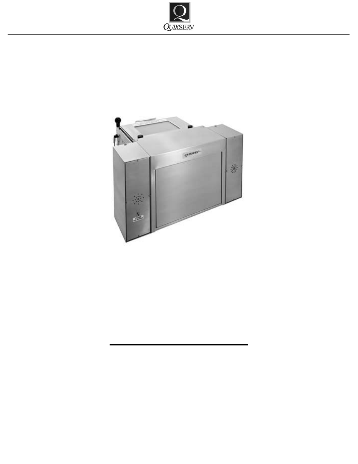
Service Manual
QSB-12 & QSB-12S
QSB-12 & QSB-12S
Service Manual
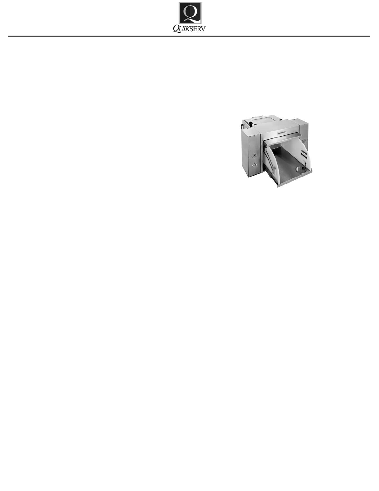
Service Opening – 13 1/4” x 9” x 23”
Rough Opening – QSB-12: 18 1/4” x 15 3/4”
Rough Opening – QSB-12S (W/O FLANGE): 28 1/4” x 15 3/4”
Rough Opening – QSB-12S (W/ FLANGE): 28 3/4” x 16”
Click the Procedure to View
Operation and Maintenance Procedures 2
Rear Carriage Lock Assembly Replacement 3
Rail Replacement 4
Coil Spring Removal 5
Rear Loading Door Lock Assembly 6
Removal of Handle Assembly 7
Roller Wheel Replacement 8
Warranty Service Policy 9
Quikserv Corp.© quikserv.com • 1-800-388-8307 • Fax (713) 849-5708
1
Page 2
Service Manual
QSB-12 & QSB-12S
Operation and Maintenance Procedures
Bullet Resistant Drawer
Operation and Maintenance Procedures
Operation Procedures
• Unlock all locking mechanisms and ensure
that the drawer is free of obstructions.
• Operate the drawer and return to the closed
position.
• The attendant serving door must be closed
and should not be opened while the attendant
is sliding the drawer unit out to service the
customer.
QSB-12 & QSB-12S
General Cleaning Guidelines:
• All drawers should be kept clean and free of
debris.
• Slide rails should be frequently cleaned, oiled,
and checked for debris and build-up.
• All cleaning uids and applicators should be
non-abrasive.
Quikserv Corp.© quikserv.com • 1-800-388-8307 • Fax (713) 849-5708
2
Page 3
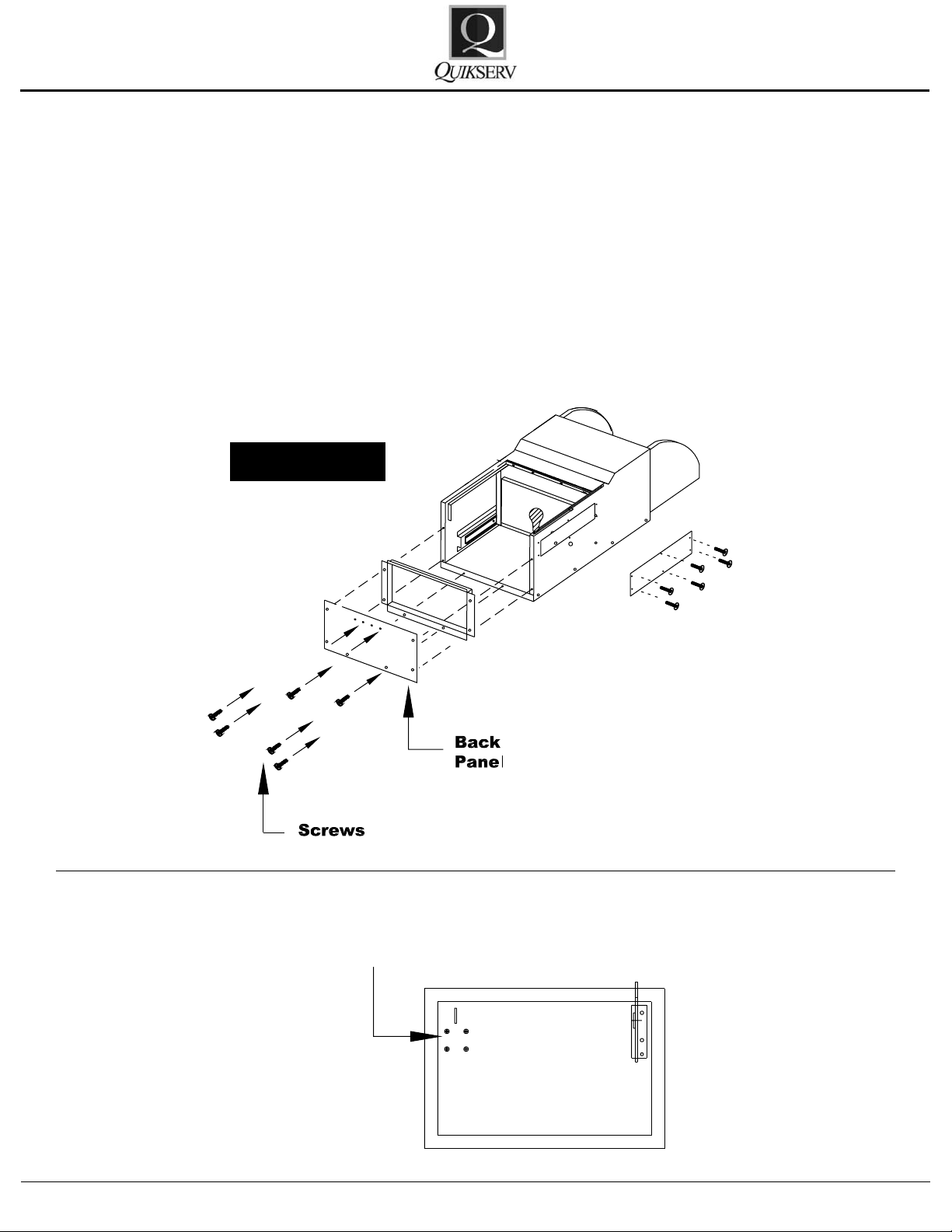
BACK PANEL
Rear Carriage
Lock Assembly
Service Manual
QSB-12 & QSB-12S
Rear Carriage Lock Assembly Replacement - Part No. 8006
1. Remove 10 screws holding back panel to
drawer.
2. Remove back panel.
3. Slide the 2 back sections apart to access the
lock assembly.
4. Remove the 4 screws holding the lock assembly to the back panel. Note: Don’t lose the pin
during disassembly.
5. Replace with new lock assembly part # 8806.
6. To reassemble, reverse the above procedures
using removable Loc-Tite on screws.
Figure 1
Quikserv Corp.© quikserv.com • 1-800-388-8307 • Fax (713) 849-5708
3
Page 4

Rail
Rail
Bottom Part
of Handle
2 Screws
Holding
Slide Rails
Service Manual
Rail Replacement - Part No. 8008
1. Push open drawer; remove 4 screws on the
bottom interior drawer that holds rails to the
bottom of drawer.
2. Remove 4 screws on the bottom part of handle (part # 8807) from interior drawer.
3. Pull drawer out.
4. Move slide rail backward or forward until the
2 screws that are holding the slide rail to the
side of the drawer is shown.
5. Remove the 2 screws and remove the slide
rail.
6. After replacing the slide rails, reverse the
above procedures to reassemble using removable Loc-Tite on screws.
QSB-12 & QSB-12S
Figure 2
Quikserv Corp.© quikserv.com • 1-800-388-8307 • Fax (713) 849-5708
4
Page 5

Bolt
Bolt
Coil Spring
Service Manual
Coil Spring Removal - Part No. 8021
1. Remove 2 bolts holing spring bracket assembly (part # 8808).
2. Remove spring from bracket.
3. Replace with new spring.
4. After replacing the spring, reverse the above
procedures using removable Loc-Tite on
screws.
QSB-12 & QSB-12S
Figure 3
Quikserv Corp.© quikserv.com • 1-800-388-8307 • Fax (713) 849-5708
5
Page 6

Service Manual
Rear Loading Door Lock Assembly - Part No. 8805
1. Remove the 2 screws holding the lock assemble to back panel.
2. Replace with new lock assemble (part
#8806).
3. Replace 2 screws using removable Loc-Tite.
QSB-12 & QSB-12S
Figure 4
Note 1
Quikserv Corp.© quikserv.com • 1-800-388-8307 • Fax (713) 849-5708
6
Page 7

Cover
Panel
Service Manual
Removal of Handle Assembly - Part No. 8807
1. Remove 6 screws on cover panel and remove
cover.
2. Move handle unit 7/16” bolt show in hole slot.
a. Remove nut from inside drawer handle.
The handle will now be in two parts.
3. To remove top handle, slide to front of the
drawer pull up and out.
4. To remove bottom of handle. Remove 4 screws
holding the handle to interior of drawer. Slide
handle to hole slot and remove.
5. To replace, reverse the above procedures using removable Loc-Tite on screws.
QSB-12 & QSB-12S
Figure 5
Quikserv Corp.© quikserv.com • 1-800-388-8307 • Fax (713) 849-5708
7
Page 8

Rail
Rail
Door
A-A
A-A
Roller
Wheel
Service Manual
Roller Wheel Replacement - Part No. 1032
1. Push open drawer and remove 4 screws on
the bottom interior drawer that holds the rails
to the bottom of drawer.
2. Remove 4 screws on the bottom part of handle (part #8807).
3. Remove screw holding the roler wheel.
4. Replace with new roller wheel (part #1032)
using removable Loc-Tite on screws.
QSB-12 & QSB-12S
Figure 6
Quikserv Corp.© quikserv.com • 1-800-388-8307 • Fax (713) 849-5708
8
Page 9

Service Manual
Warranty Service Policy
QSB-12 & QSB-12S
1. Quikserv Corp. MUST be notied of a warranty situation before any work is performed.
Otherwise, Quikserv Corp. will not be responsible to pay for unauthorized work.
2. Quikserv Corp. requires the following on each
invoice submitted: an itemized account of work
performed detailing hours charged and parts
used, along with a short detailed description
of the problem noted.
3. Quikserv Corp. will authorize a set dollar
amount to be invoiced prior to performing services that will be rendered. This amount will
be determined from the initial call to the service company as a fair maximum. If additional
amounts are to be invoiced, they must be discussed with Quikserv Corp. prior to invoicing.
4. A service technician on a warranty service call
needs to call our customer service department
at (800) 388-8307 or (713) 849-5882 before
leaving the job site.
5. A service company representative needs to
call the store where the work is to be performed prior to going to that store. Set up a
date and approximate time of arrival and if it
is foreseen that the agreed upon time cannot
be met, contact the store and make other arrangements.
7. Quikserv Corp. needs to be notied of any extra parts - either to be sent back or to be kept
by the service technician. Any parts that were
replaced must be returned to Quikserv Corp.
if required verbally or on the service work order copy supplied with the parts sent by Quikserv Corp. If the parts are not returned, the
part cost + mark up will be deducted from the
service invoice.
8. A purchase order number will be given either
verbally or on the service work order from
Quikserv Corp. Please use this on all invoicing.
9. Work required on a window unit not covered
under Quikserv’s warranty must be reported
to Quikserv Corp. before work is begun.
10. Quikserv’s payment terms are net 30. The information above will help us assure the fast-
est and most efcient service possible. For
further information or if you have any questions, please do not hesitate to contact us at
(800) 388-8307.
Customer Service Department
6. Warranty parts sent to service companies are
parts previously decided on that should cover
the necessary repairs. Additional parts will be
sent upon notication to Quikserv Corp.
Quikserv Corp.© quikserv.com • 1-800-388-8307 • Fax (713) 849-5708
9
 Loading...