


BP-7241E
Service Manual
BP-7241E
BP-7241E
Service Manual
Click the Procedure to View
Operation and Maintenance Procedures 2
Component Rack Assembly 3
Limit Switch and Door Flag Adjustment 4
Window Does Not Operate 5
Motor runs, but Door Does Not Operate 5
Door or Doors Stay in the Open Position 6
Motor Will Run for a Short Period Then Stops 7
Doors Are Dragging or Binding 7
Electrical Component Layout 8
Replacement Parts 9
Warranty Service Policy 10
Quikserv Corp.© quikserv.com • 1-800-388-8307 • Fax (713) 849-5708
1
Service Manual
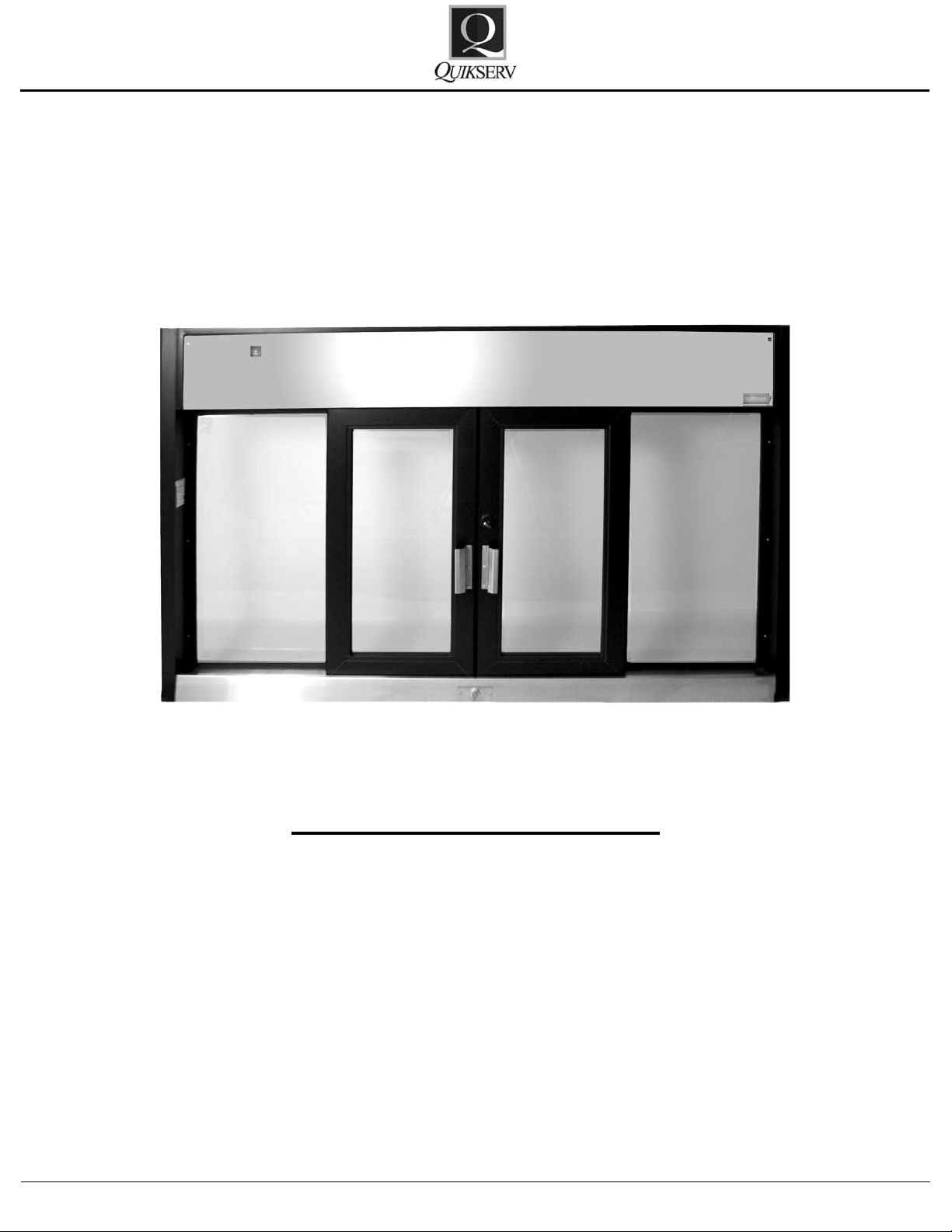
BP-7241E
Automatic Slider
Operation and Maintenance Procedures
Operation Procedures:
• Unlock all locking mechanisms and ensure
that the doors are free of obstructions.
• Turn the Power Switch to the “on” position,
located on the upper left hand corner.
• Proper operation of the “Up-Eye” unit requires
the attendant to be directly in front of and
over all 3 photoelectric sensors while serving. Proper operation of the “Thru-Beam” unit
requires the attendant to stand between the
Emitter and Receiver eyes.
• <Note> The outside edge of the photo-bar
should be lined up with the outside edge of
the locking jamb.
General Cleaning Guidelines:
• All weather-stripping should be checked and
cleaned weekly.
• All glass, aluminum framing, stainless steel,
and plastic eye covers & lens should be kept
clean at all times. All cleaning uids and ap-
plicators should be non-abrasive.
General Maintenance:
• Slide rail system should be kept clean and reoiled with lightweight oil every six (6) months.
• The hook lock and thumb turn should be
cleaned of any grease or grime build up every
six (6) months.
• The eye covers, whether “Up-Eye” or “ThruBeam, should be cleaned of any dirt or debris
daily with a non-abrasive cleaner.
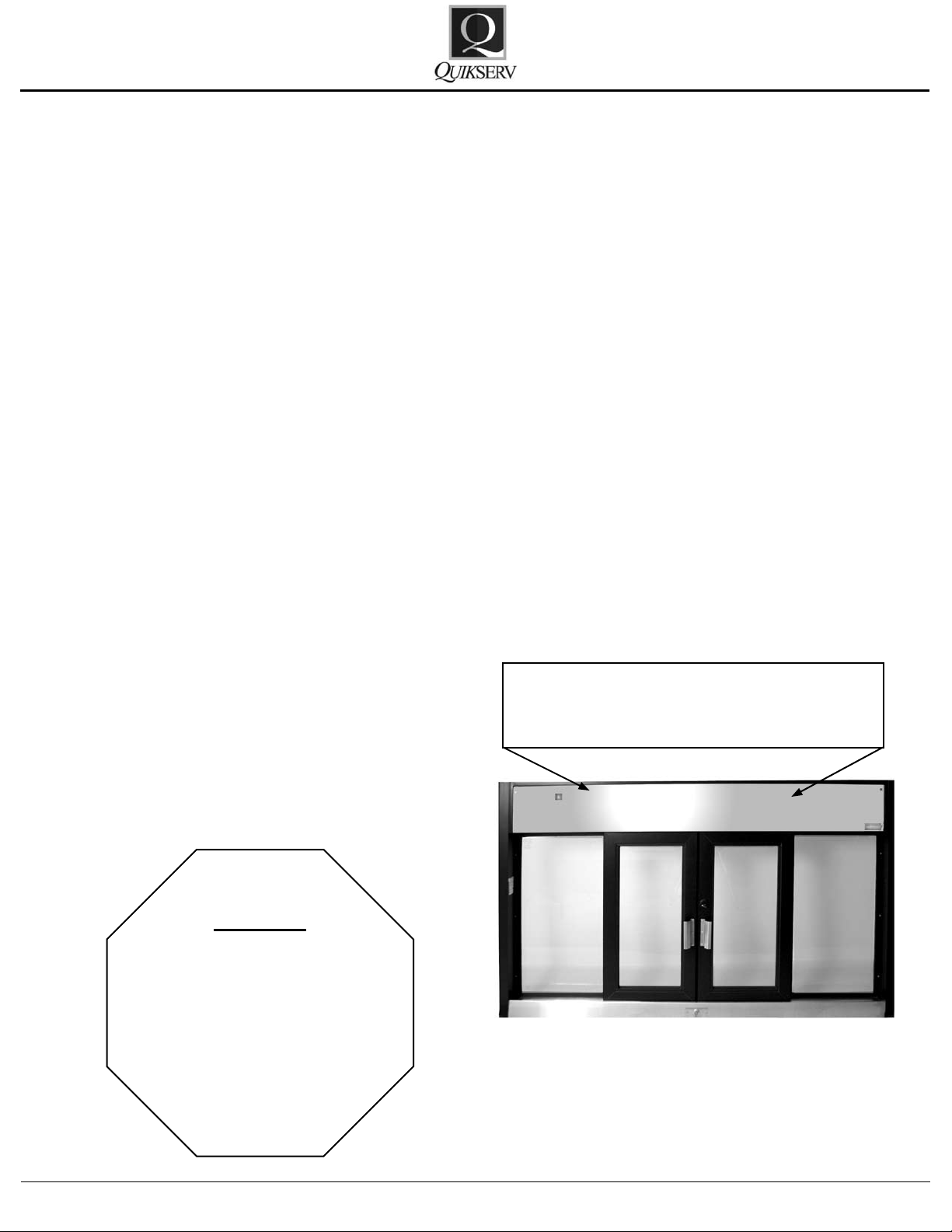
To gain access to the internal components for each window, the access panel
must be removed
Warning
For your own safety, turn
power switch OFF before
removing the access
panel.
Quikserv Corp.© quikserv.com • 1-800-388-8307 • Fax (713) 849-5708
2
Service Manual
BP-7241E
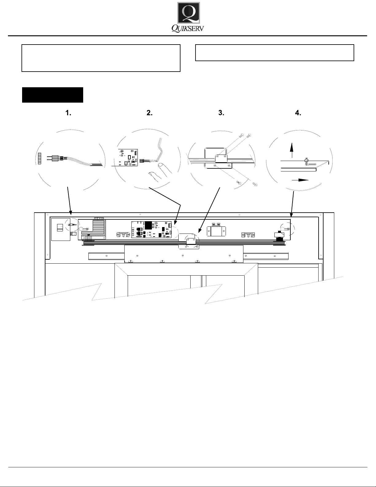
Warning: For your own safety, turn power
switch OFF before removing access panel
Figure 2
CAUTION: Power Supply = 120 V
Component Rack Assembly
To remove the component rack assembly - see
Figure 2:
1. Unplug power cord from the internal outlet.
2. Remove the
3. Disconnect theag bracket(s)from the door
bracket.
4. Loosen the two (2) 7/16” nuts at each end of
the component rack.
5. Remove component rack assembly by sliding
rack to the right and lifting out.
Quikserv Corp.© quikserv.com • 1-800-388-8307 • Fax (713) 849-5708
lower 5-pin connector.
Please refer to the TROUBLE SHOOTING
CHART in this section for additional information
on the window adjustments or service procedures.
Contact us at (800) 388-8307 for assistance or
for information on the nearest service center in
your area.
3
 Loading...