

Page 1
Service Manual
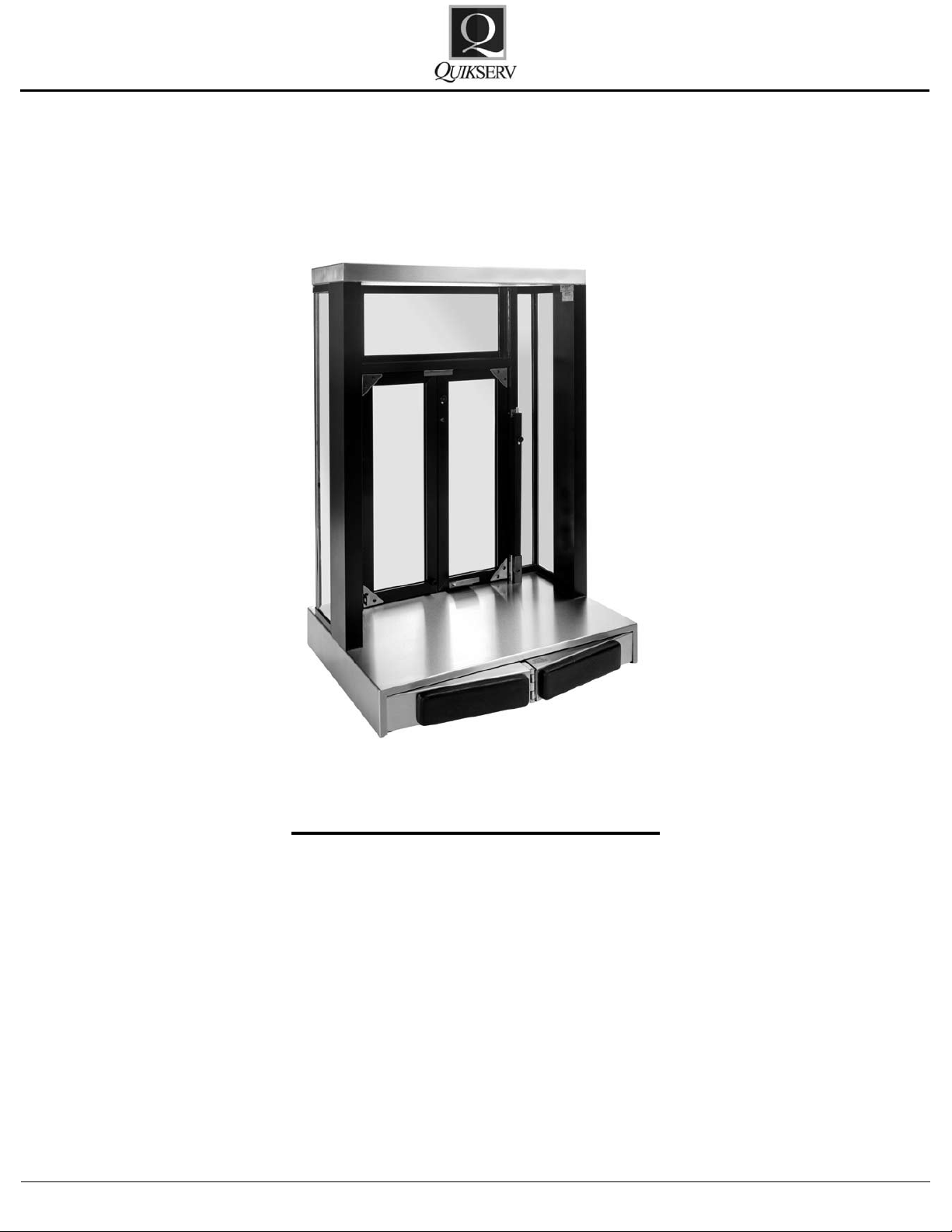
PW 1 & 2
PW 1 & 2
Semi-Automatic Bi-Fold Units
Click the Procedure to View
Operation and Maintenance Procedure 2
Only Right or Left Door Opens 3
Doors Are Misaligned 4
Door Does Not Open 5
Push Bar Remains Under Base 5
Doors are Not Closing 6
Hardware Details 7-8
Strap Details 9
Adjustment Details 10-11
Replacement Procedure 11-13
Warranty Service Policy 14
Quikserv Corp.© quikserv.com • 1-800-388-8307 • Fax (713) 849-5708
1
Page 2
Service Manual
PW 1 & 2
Semi-Automatic Bi-Fold Units
Operation and Maintenance Procedures
Pre-Operation Procedures:
• Unlock all locking mechanisms and ensure
that the doors are free of obstructions.
General Cleaning Guidelines:
• All weather-stripping should be checked and
cleaned weekly.
• All glass, aluminum framing, and stainless
steel should be kept clean at all times. All
cleaning uids and applicators should be non-
abrasive.
General Maintenance:
• Straps should be checked for fraying and for
the correct tension every 6 months.
• Straps noted as frayed or loose should be replaced or adjusted.
• The Upper and Lower sections of the pushbar assembly should be kept clean of dirt or
grease build-up.
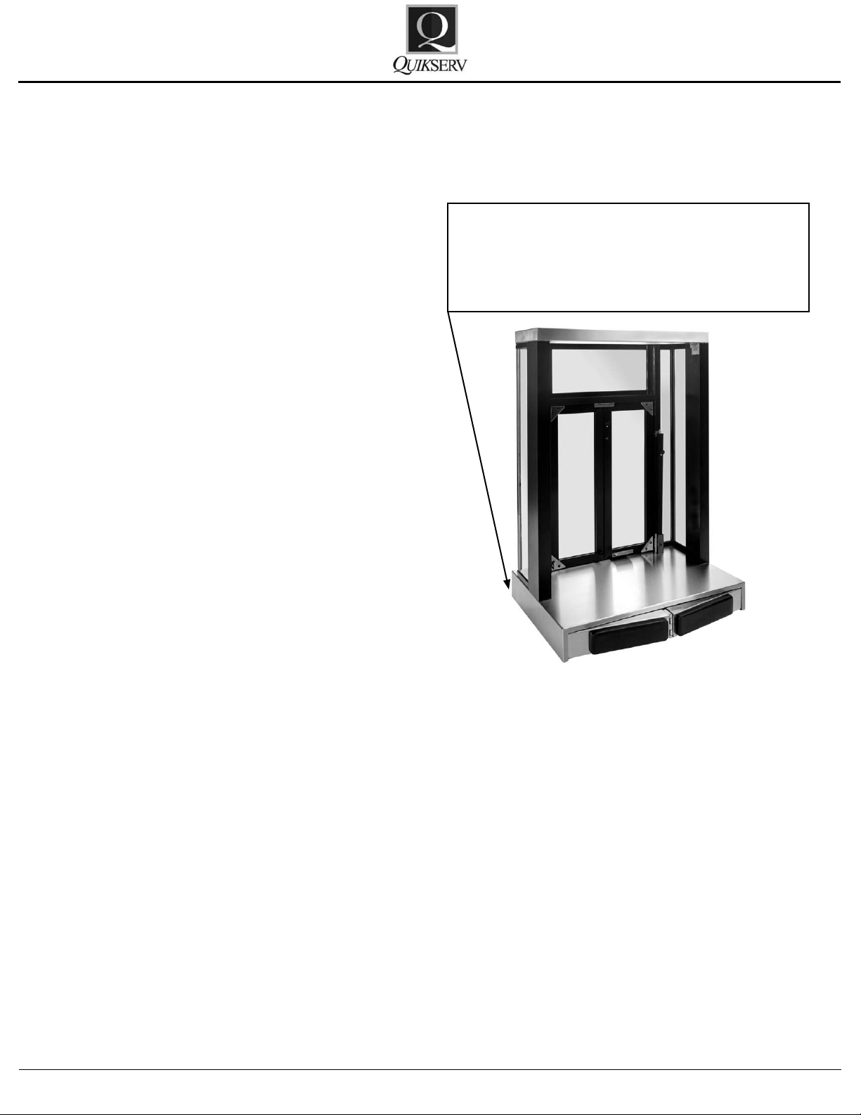
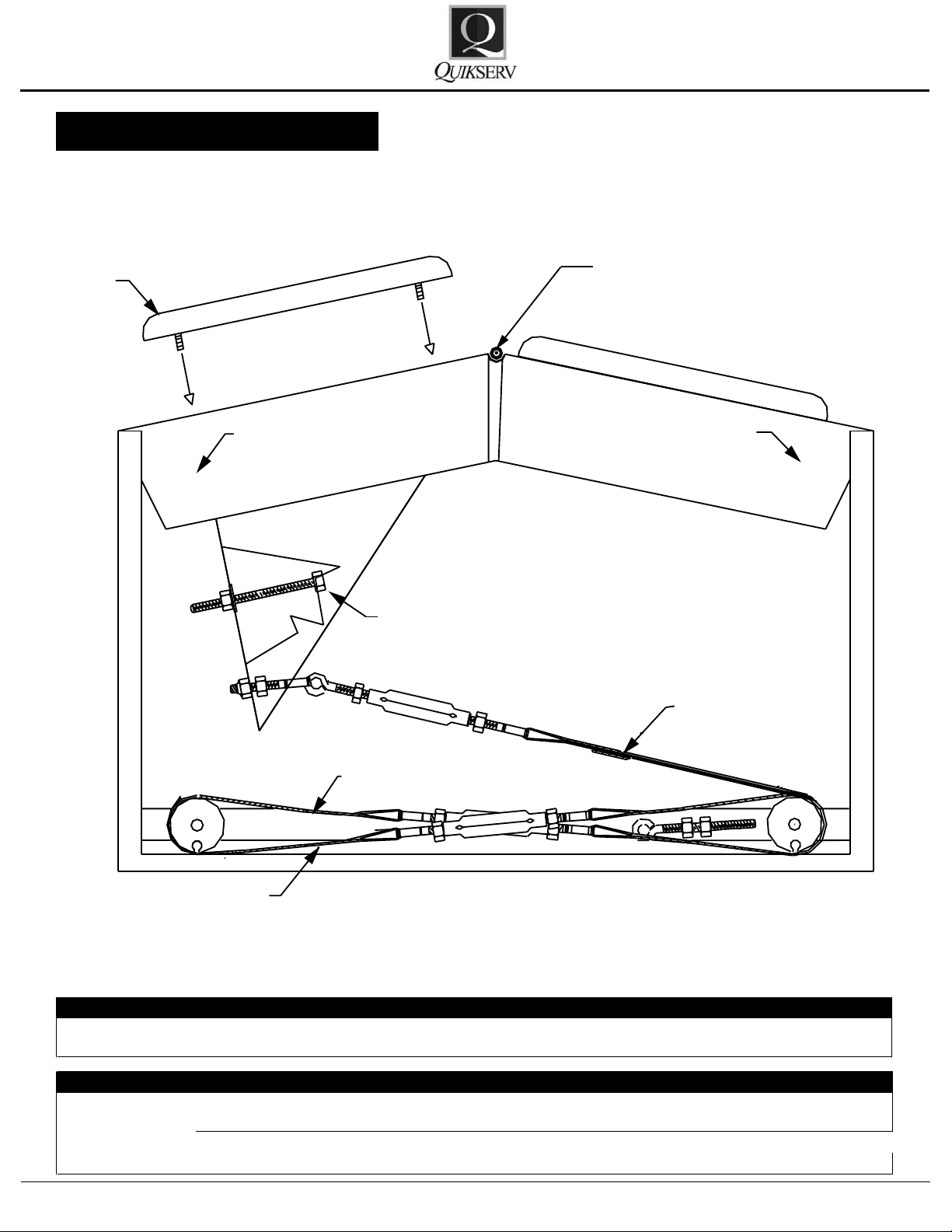
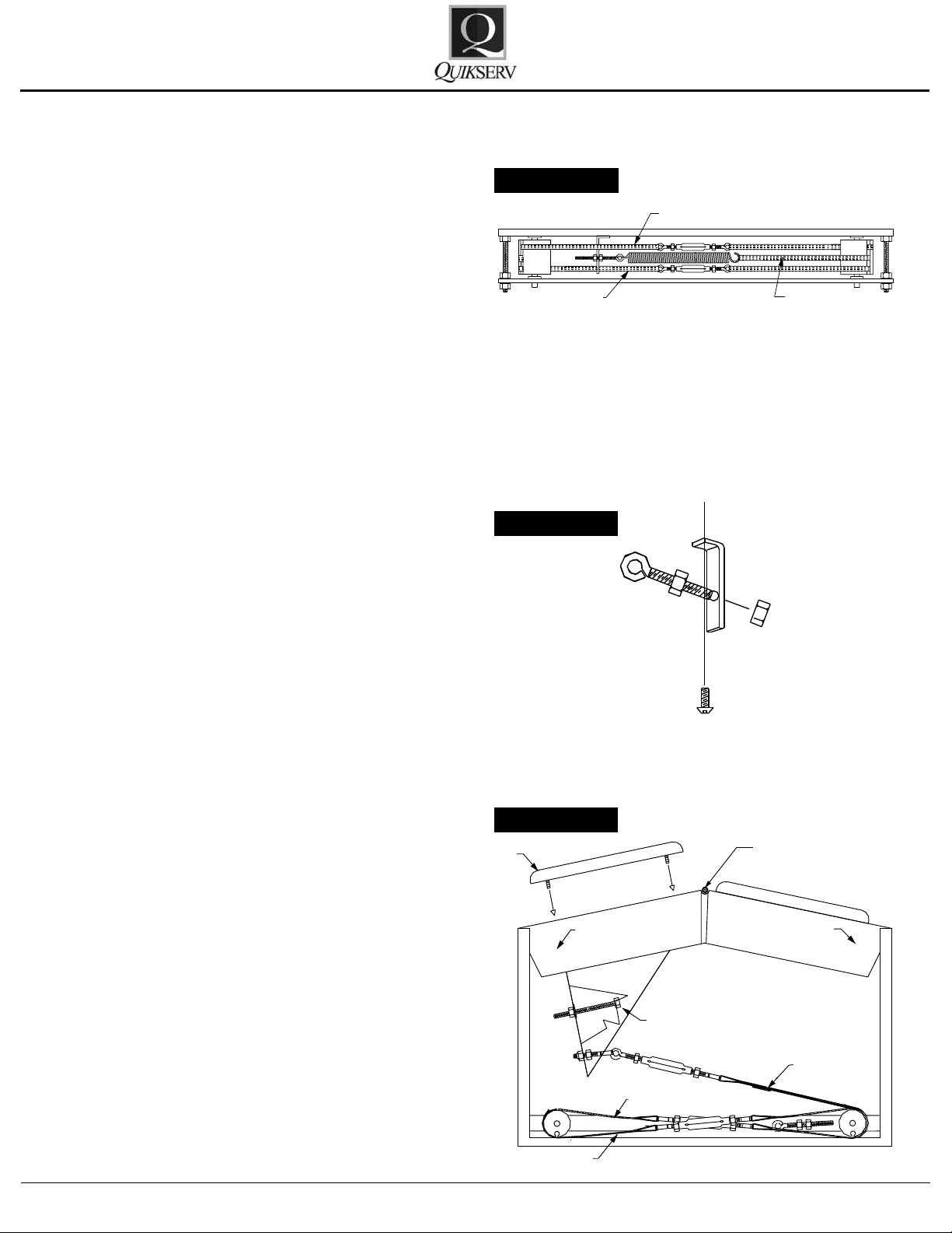
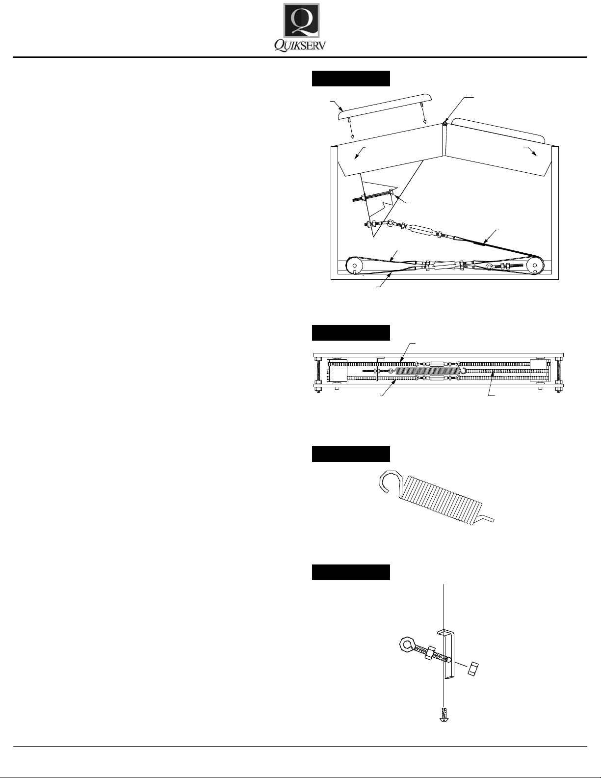
To gain access to the internal components for each window the access panel
must be removed from the exterior of the
window - see arrows below.
• Bottom hinge bearings should be oiled every 6
months.
Please refer to the TROUBLE SHOOTING
CHARTS in this section for additional information on the window adjustments or service procedures.
Contact us at (800) 388-8307 for assistance or
for information on the nearest service center in
your area.
Quikserv Corp.© quikserv.com • 1-800-388-8307 • Fax (713) 849-5708
2
Page 3
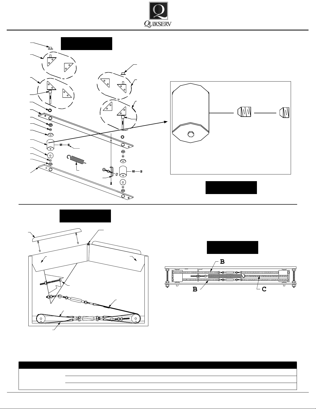
Trouble Probable Cause Probable Solution
1. Loose roller strap assembly (Part # 5566) Adjust and tighten (Fig. 8-B)
2. Broken roller strap assembly (Part # 5566) Replace and adjust (Fig. 8-B)
3. Loose roller set screws(s) (Part # 5587) Adjust and tighten (Fig. 7-E)
Only the Right
or Left Door
Opens
P
J
K
M
I
C
O
D
P
B
F
L
A
C
N
SET SCREWS
I
P
F
C
D
O
E
D
B
L
M
2 EA.
G
H
P
K
J
M
Set of Screws
2 Each
H
F
B
B
D
E
F
A
Service Manual
PW 1 & 2
Figure 7
Figure 7-E
Figure 8
Bottom View
Quikserv Corp.© quikserv.com • 1-800-388-8307 • Fax (713) 849-5708
3
Figure 8-B
Front View
Page 4
Trouble Probable Cause Probable Solution
1. Loose roller strap assembly (Part # 5566) Adjust and tighten (Fig. 8-B)
2. Broken roller strap assembly (Part # 5566) Replace and adjust (Fig. 8-B)
3. Loose roller set screws(s) (Part # 5587) Adjust and tighten (Fig. 7-E)
Trouble Probable Cause Probable Solution
1. The roller strap assembly, upper or lower, is
loose or stretched
(
Part # 5566
)
Adjust and tighten (Fig. 8-B)
2. Loose set of screw(s) (Part # 5587) Adjust and tighten (Fig. 7-E)
3. Bent hinge (Part # - 5590, 5591, 5592 & 5593)
Replace (Fig. 7-I, J, K, L)
Only the Right
or Left Door
Opens
Doors are Misaligned
P
J
K
M
I
C
O
D
P
B
F
L
A
C
N
SET SCREWS
I
P
F
C
D
O
E
D
B
L
M
2 EA.
G
H
P
K
J
M
Set of Screws
2 Each
Service Manual
PW 1 & 2
Figure 7
Figure 7 - J
Figure 7 - K
Figure 7 - L
Figure 7 - E
Quikserv Corp.© quikserv.com • 1-800-388-8307 • Fax (713) 849-5708
Figure 7 - I
Figure 8 - B
All left and right designations are shown from the
operator’s point of view, or inside looking out of the
window unit
4
Page 5
Trouble Probable Cause Probable Solution
1. Loose roller strap assembly (Part # 5566) Adjust and tighten (Fig. 8-B)
2. Broken roller strap assembly (Part # 5566) Replace and adjust (Fig. 8-B)
3. Loose roller set screws(s) (Part # 5587) Adjust and tighten (Fig. 7-E)
Trouble Probable Cause Probable Solution
1. The roller strap assembly, upper or lower, is
loose or stretched
(
Part # 5566
)
Adjust and tighten (Fig. 8-B)
2. Loose set of screw(s) (Part # 5587) Adjust and tighten (Fig. 7-E)
3. Bent hinge (Part # - 5590, 5591, 5592 & 5593)
Replace (Fig. 7-I, J, K, L)
Trouble Probable Cause Probable Solution
Door Does Not
O
p
en
1. The pull-strap assembly is loose or broken
(
Part # 5567
)
Replace. Or, adjust and tighten (Fig. 8-A)
Only the Right
or Left Door
Opens
Doors are
Misaligned
Trouble Probable Cause Probable Solution
1. Loose roller strap assembly (Part # 5566) Adjust and tighten (Fig. 8-B)
2. Broken roller strap assembly (Part # 5566) Replace and adjust (Fig. 8-B)
3. Loose roller set screws(s) (Part # 5587) Adjust and tighten (Fig. 7-E)
Trouble Probable Cause Probable Solution
1. The roller strap assembly, upper or lower, is
loose or stretched
(
Part # 5566
)
Adjust and tighten (Fig. 8-B)
2. Loose set of screw(s) (Part # 5587) Adjust and tighten (Fig. 7-E)
3. Bent hinge (Part # - 5590, 5591, 5592 & 5593)
Replace (Fig. 7-I, J, K, L)
Trouble Probable Cause Probable Solution
Door Does Not
O
p
en
1. The pull-strap assembly is loose or broken
(
Part # 5567
)
Replace. Or, adjust and tighten (Fig. 8-A)
Trouble Probable Cause Probable Solution
1. Return spring nees adjustment (Part # 1009) Adjust and tighten (Fig. 7-G & 7-H)
2. Return spring or strap is broken (Part # 1009 &
5568
)
Replace and adjust (Fig. 7-G or 8-C)
3. Push bar is dragging Check bottom plate for proper installation -
if not install properly contact Quikserv
Cor
p
.
4. Doors are dragging
Loosen hinge screws and realign door
(Fig
. 7-I, J, K, & L
)
Trouble Probable Cause Probable Solution
1. Travel ad
j
uster is loose or broken (Part # 5201
)
Replace or adjust and tighten(Fig. 8-D
)
2. Pull strap is broken (Part # 5567
)
See replacementprocedures
Only the Right
or Left Door
Opens
Doors are
Misaligned
Doors are not
closing
Push Bar Remains Under Base
H
F
B
B
D
E
F
A
Service Manual
Figure 8 - A & 8 - D
PW 1 & 2
Bottom View
Quikserv Corp.© quikserv.com • 1-800-388-8307 • Fax (713) 849-5708
5
Page 6

Trouble Probable Cause Probable Solution
1. Loose roller strap assembly (Part # 5566) Adjust and tighten (Fig. 8-B)
2. Broken roller strap assembly (Part # 5566) Replace and adjust (Fig. 8-B)
3. Loose roller set screws(s) (Part # 5587) Adjust and tighten (Fig. 7-E)
Trouble Probable Cause Probable Solution
1. The roller strap assembly, upper or lower, is
loose or stretched
(
Part # 5566
)
Adjust and tighten (Fig. 8-B)
2. Loose set of screw(s) (Part # 5587) Adjust and tighten (Fig. 7-E)
3. Bent hinge (Part # - 5590, 5591, 5592 & 5593)
Replace (Fig. 7-I, J, K, L)
Trouble Probable Cause Probable Solution
Door Does Not
O
p
en
1. The pull-strap assembly is loose or broken
(
Part # 5567
)
Replace. Or, adjust and tighten (Fig. 8-A)
Trouble Probable Cause Probable Solution
1. Return spring nees adjustment (Part # 1009) Adjust and tighten (Fig. 7-G & 7-H)
2. Return spring or strap is broken (Part # 1009 &
5568
)
Replace and adjust (Fig. 7-G or 8-C)
3. Push bar is dragging Check bottom plate for proper installation if not install properly contact Quikserv
Cor
p
.
4. Doors are dragging
Loosen hinge screws and realign door
(Fig
. 7-I, J, K, & L
)
Only the Right
or Left Door
Opens
Doors are
Misaligned
Doors are not closing
P
J
K
M
I
C
O
D
P
B
F
L
A
C
N
SET SCREWS
I
P
F
C
D
O
E
D
B
L
M
2 EA.
G
H
P
K
J
M
Service Manual
PW 1 & 2
Figure 7
Figure 7 - I
Figure 7 - J
Figure 7 - K
Figure 7 - G
Figure 7 - H
Quikserv Corp.© quikserv.com • 1-800-388-8307 • Fax (713) 849-5708
Figure 7 - L
All left and right designations are shown from the
operator’s point of view, or inside looking out of the
window unit
6
Page 7

Set of Screws
2 Each
Service Manual
Hardware Details
Key No. Part No. Description
A 5524 Bottom Bearing Bar (Includes Bearings)
B 5525 Upper Bearing Bar (Includes Bearings)
C 1012 Bearing
PW 1 & 2
D 1004 Roller Spacer Bushing
E 5587 Aluminum Roller - Set Screws
F 1013 Rubber O-Ring
G 1009 Return Spring
H 3702 Return Spring Bracket
All left and right designations are shown from the
operator’s point of view, or inside looking out of the
window unit
Quikserv Corp.© quikserv.com • 1-800-388-8307 • Fax (713) 849-5708
7
Page 8

Service Manual
Key No. Part No. Description
I 5590 L/H Bottom Hinge Assembly
J 5591 R/H Bottom Hinge Assembly
K 5593 R/H Top Hinge Assembly
PW 1 & 2
L 5592 L/H Top Hinge Assembly
M 1006 Top Hinge Bushing
N 3631 Bottom Retainer Washer
O 3643 Top Retainer Washer
P 1915 Hinge Space Bushing
All left and right designations are shown from the
operator’s point of view, or inside looking out of the
window unit
Quikserv Corp.© quikserv.com • 1-800-388-8307 • Fax (713) 849-5708
8
Page 9

Key No. Part No. Description
A 5567 Pull Strap Assembly
B 5566 Roller Strap Assembly (2)
C 5568 Return Strap Assembly
D 5201 Travel Adjuster
E 2103 Push Pad
F * Push Bar Assembly
G 5596 Complete Set of Straps
H 1914 Hinge Pin
H
F
B
B
D
E
F
A
B
C
B
Service Manual
Bottom View
PW 1 & 2
Strap Details
Exterior View
Quikserv Corp.© quikserv.com • 1-800-388-8307 • Fax (713) 849-5708
9
Page 10
B
C
B
H
F
B
B
D
E
F
A
Service Manual
PW 1 & 2
Adjustment Procedures
Roller Strap Adjustment:
1. Loosen both 7/16” nuts on Part #5566 (Fig.
8-B).
2. Insert any average size screwdriver through
one eyebolt on Part #5566.
3. Hold the other eyebolt on turnbuckle between
thumb and forenger; turn adjuster body
clockwise or counter-clockwise with a 7/16”
open-end wrench until doors are aligned.
4. Realign eyebolts so they are not rubbing on
the return spring or any other object.
5. Tighten locknuts and apply non-perma
nent thread-lock.
Return Spring Adjustment:
1. Loosen locknut on Part # 3702 with a 7/16”
open-end wrench. (Fig. 7-H)
2. Turn eyebolt clockwise to increase pressure,
counter-clockwise to decrease pressure.
3. Tighten locknuts and apply non-perma-
nent thread-lock.
Figure 8 - B
-
Figure 7 - H
Pull Strap Assembly Tension Adjustment:
1. Loosen both locknuts on Part #5567 using
two 7/16” open-end wrenches. (Fig. 8-A)
2. Holding eyebolt on Part #5567 between thumb
and forenger, turn adjuster body clockwise
or counter-clockwise until slack is out of the
push bar. Caution: Do not over tighten adjuster body, as this will cause door to remain
slightly open.
3. Tighten locknuts and apply non-perma-
nent thread-lock.
Figure 8 - A
Quikserv Corp.© quikserv.com • 1-800-388-8307 • Fax (713) 849-5708
10
Page 11

Set of Screws
2 Each
B
C
B
Service Manual
PW 1 & 2
Roller Set Screw
1. Using a pair of needle nose pliers, remove return spring from adjuster eyebolt (Fig. 7-G &
H).
2. Align both doors to an equally open position
until you see the roller set screws (Part #5587
- Fig. 7-E).
3. Remove set screw with a 3/16” hex head
wrench (Note: Rollers may have 2 set screws
each).
4.
Apply non-permanent thread lock on the
set screw(s) threads.
5. Replace set screw(s), tighten, and close
doors.
6. Re-install return spring to the eyebolt.
Replacement Procedures
Figure 7 - G
Figure 7 - E
Figure 7 - H
Replacement of Roller Strap Assembly Part
#5566:
1. Turn retainer washers (Part #3631) on bottom of rollers (Part #5587) until you realign
the slots (Fig. 7-N).
2. Remove the frayed or broken strap by loosening the turnbuckle. You (See Fig. 8-B) may
rst need to loosen the opposite strap tension
in order to replace the frayed or broken strap
assembly.
3. Install the new strap set in the reverse order
that the defective strap set was removed.
Once in place, check to make sure that the
top roller strap is wrapped around the rollers
opposite of the bottom roller strap. (See front
view drawing - Fig. 8)
4. Tighten both strap sets by turning adjuster
body about halfway up the threaded eyebolts.
Tighten in sequence - a little at a time until
both roller straps are taut and both doors are
aligned in the closed position.
Figure 7 - N
Figure 8 - B
Quikserv Corp.© quikserv.com • 1-800-388-8307 • Fax (713) 849-5708
11
Page 12
H
F
B
B
D
E
F
A
B
C
B
Service Manual
PW 1 & 2
Replacement of Pull Strap Assembly Part
#5567:
1. Remove lower door roller strap (Part #5566
(Fig. 8-B) - see above procedures) from the
left side roller.
2. Loosen adjuster body on Part #5567
A) and remove strap. (Fig. 8-A) 3. Insert new
pull strap end with pin into slot on roller body.
Wrap the strap around roller in the same
manner that it was removed. Reconnect turn
buckle to eye bolt and adjust tension.
Replacement of the Return Spring Strap Assembly and Return Spring Part #5568 (Fig. 8C) & Part #1009 (Fig. 7-G):
1. Remove the 7/16” anchor nut on the eyebolt
(Part # 3702 - Fig. 7-H) and remove the broken spring (Part #1009 - Fig. 7-G) or the strap
assembly (Part #5568 - Fig. 8-C). *Note how
the strap wraps around the roller. In order to
remove the return spring strap assembly you
will have to remove the lower roller strap assembly (Fig. 8-B).
2. Insert new strap and spring with pin into roller
body in the same manner it was removed. Install other end of strap onto the return spring.
Reinstall return spring on bracket (Part # 3702
- Fig. 7-H) and adjust tension by adjusting
adjustment nuts and apply non-permanent
thread-lock.
(Fig. 8-
Figure 8 - A
Bottom View
Figure 8 - B
Front View
Figure 7 - G
Figure 7 - H
Quikserv Corp.© quikserv.com • 1-800-388-8307 • Fax (713) 849-5708
12
Page 13
Service Manual
PW 1 & 2
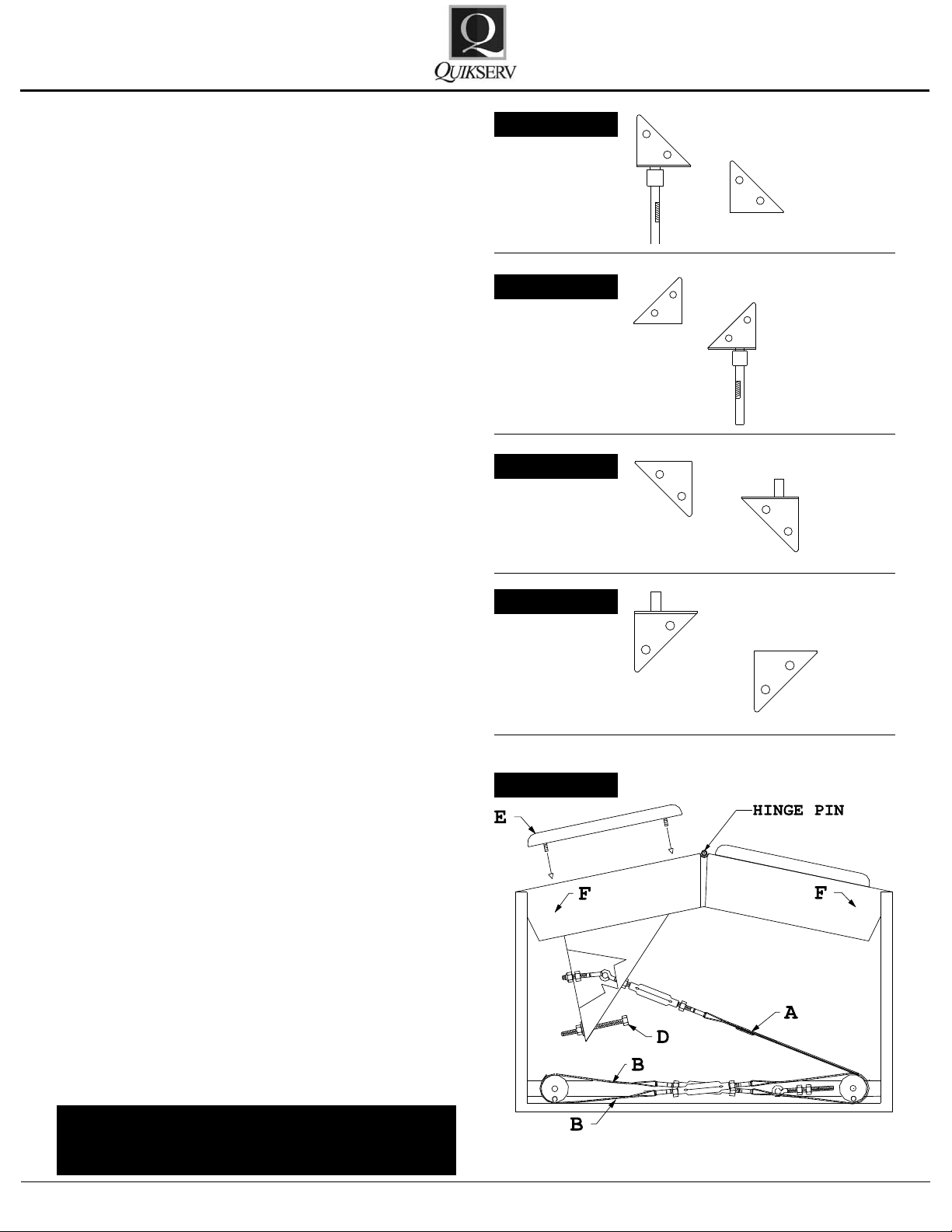
Hinge Replacement:
1. Remove hinge screws on Part #5590, 5591,
5592, and 5593 - (Fig. 7-I, J, K, L).
2. Remove door(s).
3. Remove all strap assemblies (see Replacement Procedures).
4. Remove Roller set screws (2 per roller) - Part
#5587 - Fig. 7-E.
5. Remove hinge by pulling it out of the roller
with upward force. (Note: you may have to
use pliers or vise grips).
6. Install new hinge through the top of the base.
Hinge will go through the hinge spacer, o-ring,
bearing, roller bushing, top retainer washer,
roller, bottom retainer washer, roller spacer
bushing, and bearing. See parts on Fig. 7.
7. Reinstall the hinge screws. Do not fully tighten.
After all screws are installed, align the door(s)
so that the door clearance is the same at the
top as it is at the bottom. Tighten screws.
8. Reinstall the strap assemblies and apply nonpermanent thread-lock (see Replacement
Procedures).
Figure 7 - I
Figure 7 - H
Figure 7 - H
Figure 7 - H
Push Bar Replacement:
1. Insert a small punch into the bottom of the
push bar hinge pin and drive (Fig. 8-F) the
hinge pin out of the hinge. The pin should exit
the hinge from the top.
2. Remove the right side of the push bar - then
the left side.
3. Disconnect the pull strap from the push bar
assembly.
4. Install the new push bar in reverse order.
5. Adjust travel adjuster (Fig. 8-D) so that when
the push bar is operated the push bar pads
do not travel under the base. Proper travel
adjuster alignment should leave the bolt extending out of the push bar arm approximately
1 1/2”.
All left and right designations are shown from the
operator’s point of view, or inside looking out of the
window unit
Figure 8
Bottom View
Quikserv Corp.© quikserv.com • 1-800-388-8307 • Fax (713) 849-5708
13
Page 14

Service Manual
Warranty Service Policy
PW 1 & 2
1. Quikserv Corp. MUST be notied of a warranty situation before any work is performed.
Otherwise, Quikserv Corp will not be responsible to pay for unauthorized work.
2. Quikserv Corp. requires the following on each
invoice submitted: an itemized account of work
performed detailing hours charged and parts
used, along with a short detailed description
of the problem noted.
3. Quikserv Corp. will authorize a set dollar
amount to be invoiced prior to performing services that will be rendered. This amount will
be determined from the initial call to the service company as a fair maximum. If additional
amounts are to be invoiced, they must be discussed with Quikserv Corp. prior to invoicing.
4. A service technician on a warranty service call
needs to call our customer service department
at (800) 388-8307 or (713) 849-5882 before
leaving the job site.
5. A service company representative needs to
call the store where the work is to be performed prior to going to that store. Set up a
date and approximate time of arrival and if it
is foreseen that the agreed upon time cannot
be met, contact the store and make other arrangements.
7. Quikserv Corp. needs to be notied of any extra parts - either to be sent back or to be kept
by the service technician. Any parts that were
replaced must be returned to Quikserv Corp.
if required verbally or on the service work order copy supplied with the parts sent by Quikserv Corp. If the parts are not returned, the
part cost + mark up will be deducted from the
service invoice.
8. A purchase order number will be given either
verbally or on the service work order from
Quikserv Corp. Please use this on all invoicing.
9. Work required on a window unit not covered
under Quikserv’s warranty must be reported
to Quikserv Corp. before work is begun.
10. Quikserv’s payment terms are net 30. The information above will help us assure the fast-
est and most efcient service possible. For
further information or if you have any questions, please do not hesitate to contact us at
(800) 388-8307.
Customer Service Department
6. Warranty parts sent to service companies are
parts previously decided on that should cover
the necessary repairs. Additional parts will be
sent upon notication to Quikserv Corp.
Quikserv Corp.© quikserv.com • 1-800-388-8307 • Fax (713) 849-5708
14
 Loading...