

Service Manual
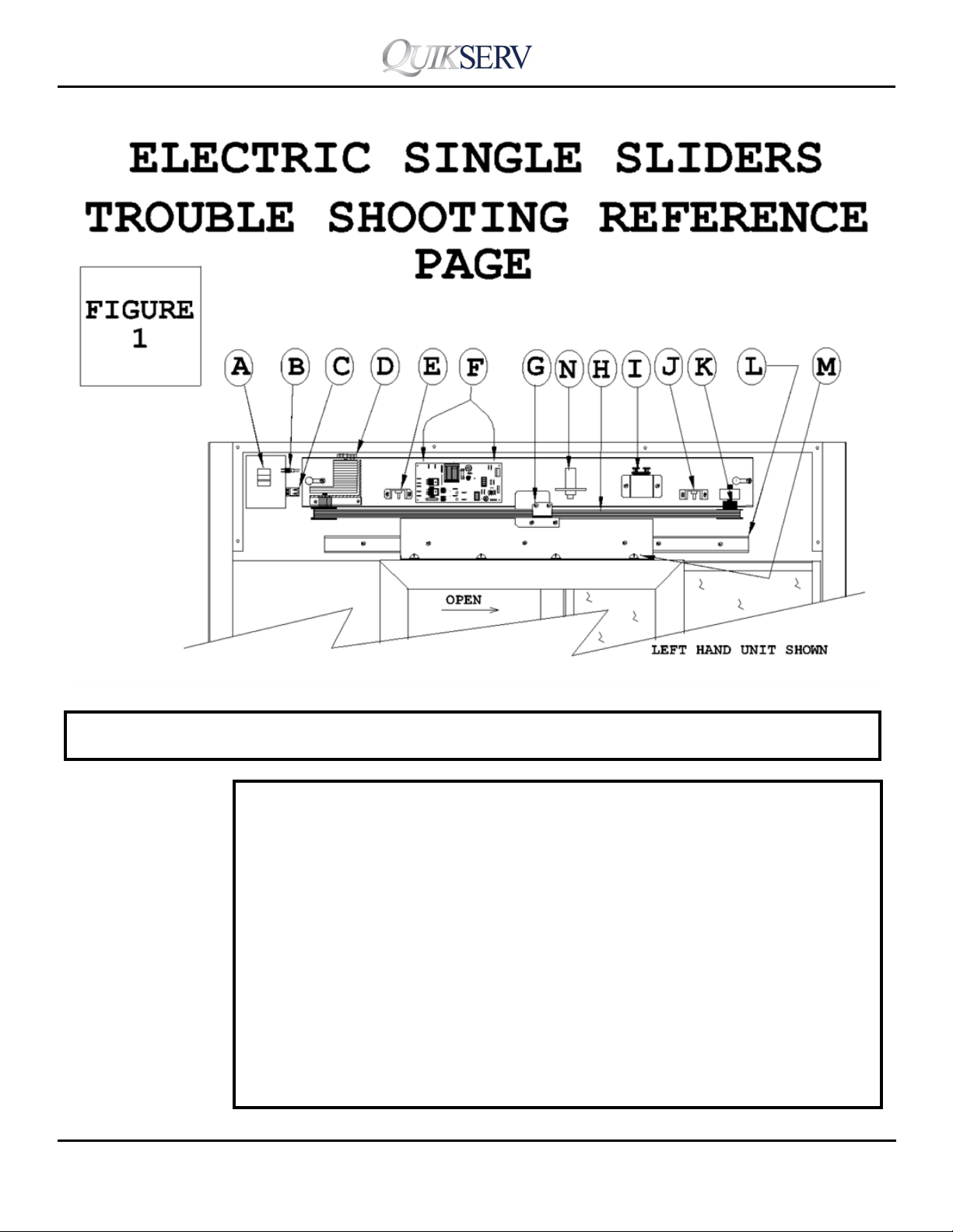
ELECTRIC SINGLE SLIDERS
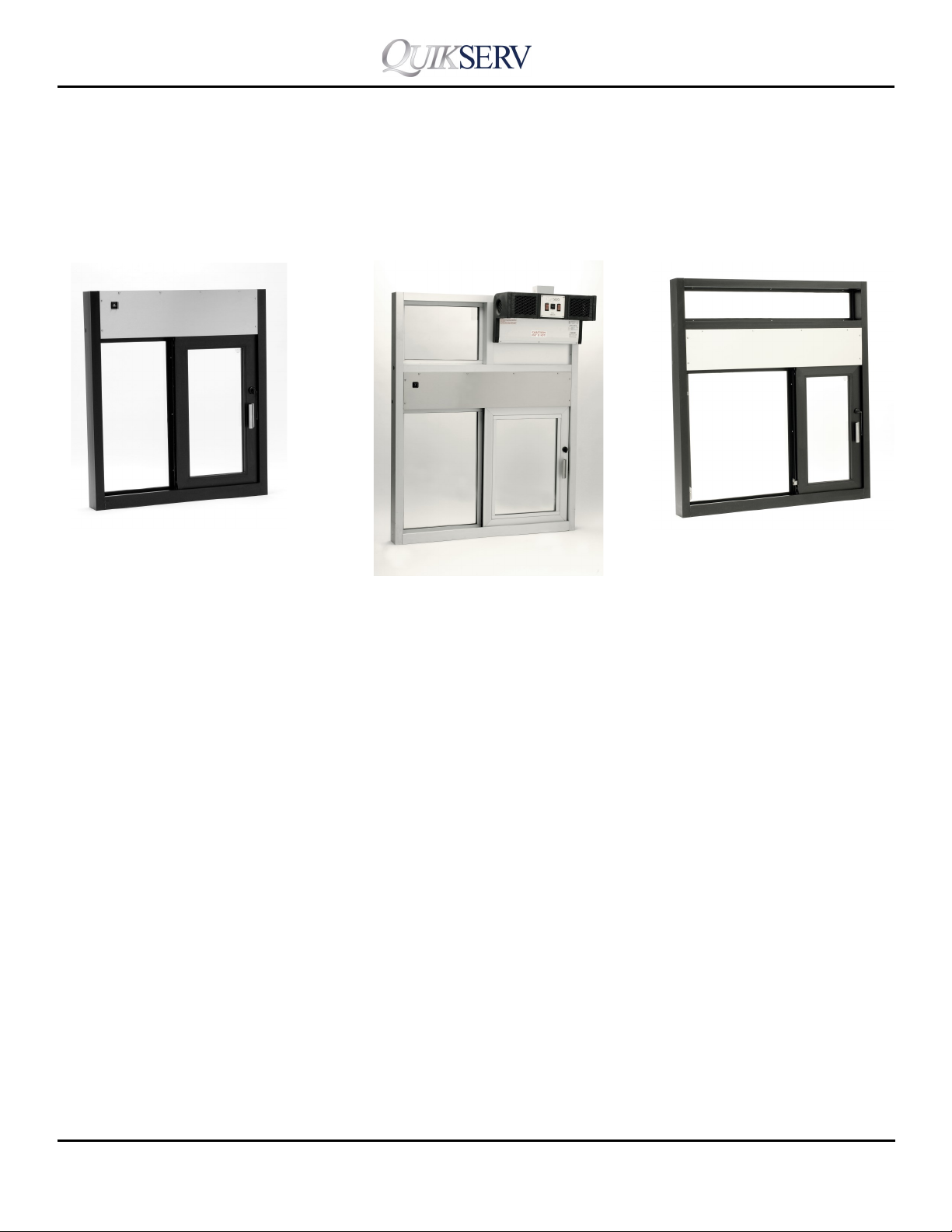
Electric Single Sliders
Service Manual
SS-4035IP
SS-4035E/SS-4538E
SS-36E
Operation and Maintenance Procedures 2
Trouble Shooting 3-6
Limit Switch Adjustment 7
Component Rack Removal 8
Parts Description 9
Window hardware Detail 10
PC Board Components 11
SST-4035E
IFT-4860E
Contents
Wiring Diagrams 12-14
Warranty Service Policy 15
Quikserv Corp. quikserv.com
• 1-800-388-8307 • Fax (713) 849-5708
1
Service Manual
Electric Single Sliders
ELECTRIC SINGLE SLIDERS
Operaon and Maintenance Procedures
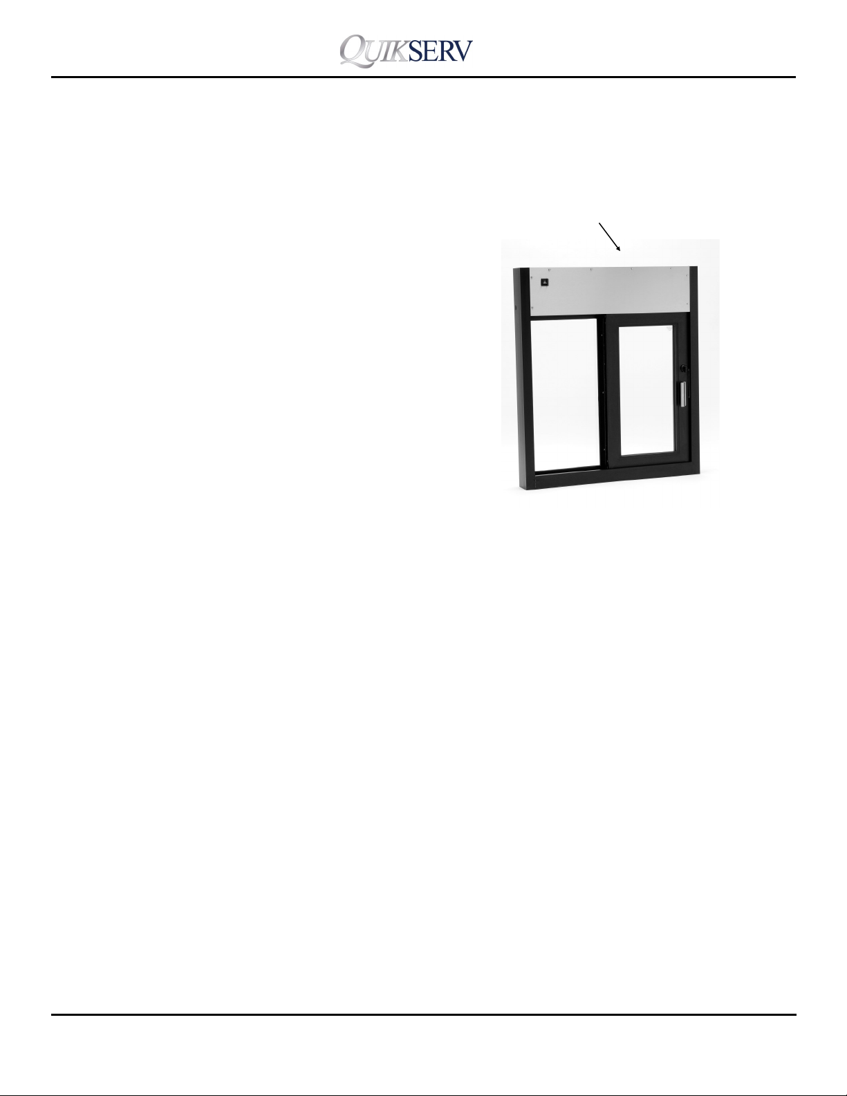
Operation Procedures:
Unlock all locking mechanisms and ensure
that the doors are free of obstructions.
Turn the power Switch to the “on” position,
located on the upper left hand corner.
(Some windows the switch may be located
behind the access cover.)
Proper operation of the “Up-Eye” unit re-
quires the attendant to be directly in front
of and over all 3 photoelectric sensors
while serving. Proper operation of the
“Thru-Beam” unit requires the attendant to
stand between the Emitter and Receiver
eyes.
Remove access cover panel to service electrical and
mechanical components
General Maintenance:
Always disconnect the power supply before
servicing.
Slide rail system should be kept clean and
re-oiled with light weight oil every six (6)
months.
<Note> The outside edge of the photo-bar
should be lined up with the inside edge of
the locking jamb.
General Cleaning Guidelines:
All weather-stripping should be checked
and cleaned weekly.
All glass, aluminum framing, stainless
steel, and plastic eye covers & lens should
be kept clean at all times. All cleaning flu-
ids and applicators should be nonabrasive.
Quikserv Corp. quikserv.com
The eye-sets should be checked weekly to
make sure they are fully fastened to unit or
wall. They should also be cleaned of any
dirt or debris daily with non-abrasive cleaner.
Please refer to the trouble shooting section for
additional information on the window adjustments or service procedures.
Contact us at (800) 388-8307 for assistance or
for information on the nearest service center in
your area.
• 1-800-388-8307 • Fax (713) 849-5708
2
Service Manual
Electric Single Sliders
Trouble Probable Cause Probable Soluon
1. No power to the unit Check the Circuit breaker
Window
Does
Not Operate
Quikserv Corp. quikserv.com
2. Power Switch is o or defecve Turn on switch or replace (Fig. 1-A)
3. Fuse in switch or pc board blown Check and Replace (Fig. 1-C or 6-B)
4. Component Rack not plugged in Check and plug in (Fig. 1-B)
5. Open limit switch defecve or discon-
nected
6. Defecve eye set Replace defecve part (Fig. 5-E or G)
7. Obstrucon in door movement Check locks, slide rail, and remove
Connue Page 4
3
Replace or reconnect (Fig. 1-E & J)
• 1-800-388-8307 • Fax (713) 849-5708
Service Manual
Electric Single Sliders
Trouble Shoong Electric Single Sliders
Trouble Probable Cause Probable Soluon
8. Defecve motor or capacitor Replace motor (Fig. 1-D & I)
Window
9. Thermal overload tripped in motor Replace or adjust limit switches (Fig. 2)
Does
Not Operate
10. Defecve PC Board Replace (Fig. 1-F)
11. Defecve slide rail Replace (Fig. 1-L)
12. Electric lock defecve or adjusted Adjust or replace (Fig. 1-N)
Trouble Probable Cause Probable Soluon
Door stay in
the open
posion
1. Closed limit switch is defecve or dis-
connected
2. Eye assembly is unplugged or discon-
nected
3. Photo-eye is obstructed or misaligned Remove obstrucon (Fig. 5-E)
4. Faulty eye wire connecon Check all connecons-repair or replace
5. Defecve PC board Replace (Fig. 1-F)
6. Handicap buon on eye-set defecve Replace switch on side of up-eyes
Replace or reconnect (Fig. 1-E & J)
Check connecon point (Fig. 5)
(Disconnued aer serial number
35700)
7. Reverse gear in motor bad Replace (Fig. 1-D)
8. Door misaligned Adjust door (Fig. 1-M)
Trouble Probable Cause Probable Soluon
Motor runs
1. Motor sha pulley or pulley block
loose
but the door
2. Broken drive belt Replace (Fig. 1-H)
does not
3. Belt bracket loose or missing Tighten or replace (Fig. 1-G)
operate
4. Bad motor Replace (Fig. 1-D)
Quikserv Corp. quikserv.com
4
Tighten or replace (Fig. 1-D or K)
• 1-800-388-8307 • Fax (713) 849-5708
Service Manual
Electric Single Sliders
Trouble Shoong Electric Single Sliders
Trouble Probable Cause Probable Soluon
Window will
run for short
1. Thermal overload in the motor has
been tripped
Limit switch or switches may not be set
properly (Fig. 2) & (Fig. 1-E & J)
period then
stop
Trouble Probable Cause Probable Soluon
Doors are
dragging or
binding
1. Slide rail is dirty or defecve Clean and oil or replace if needed. (Fig.1-
L)
2. Loose door bracket Tighten screws and make sure inserts in
door are not loose. (Fig.1-M)
3. Doors misaligned Adjust door (Fig.1-M)
3. Drive Belt too ght Loosen Drive Belt. (Fig. 1-H)
Quikserv Corp. quikserv.com
• 1-800-388-8307 • Fax (713) 849-5708
5

Service Manual
Electric Single Sliders
Trouble Shoong Electric Single Sliders
With Oponal - PUSH BUTTON -
Open & Close
Trouble Probable Cause Probable Soluon
Door(s) only
open do not
1. Defecve push buon Replace push buon (Fig. 5-H)
2. Defecve motor Replace motor (Fig. 9-D)
3. Defecve CFA- PC Board Replace CFA board (Fig. 9-A) Serial
close
numbers 40281 to 65162
4. Closed limit switch bad or disconnect-
ed
Replace or reconnect limit switch (Fig. 1
-E)
Trouble Probable Cause Probable Soluon
1. Defecve push buon Replace buon (Fig. 5-H)
Door(s) open
but close on
it’s own.
2. Defecve CFA PC Board Replace CFA Board (Fig. 9-A) Serial num-
ber 40281 to 65162
3. Rheostat adjustment on CFA board Adjust Rheostat clockwise all the way for
window to not self close. (Fig. 9-A) Serial
number 61916 to 65162
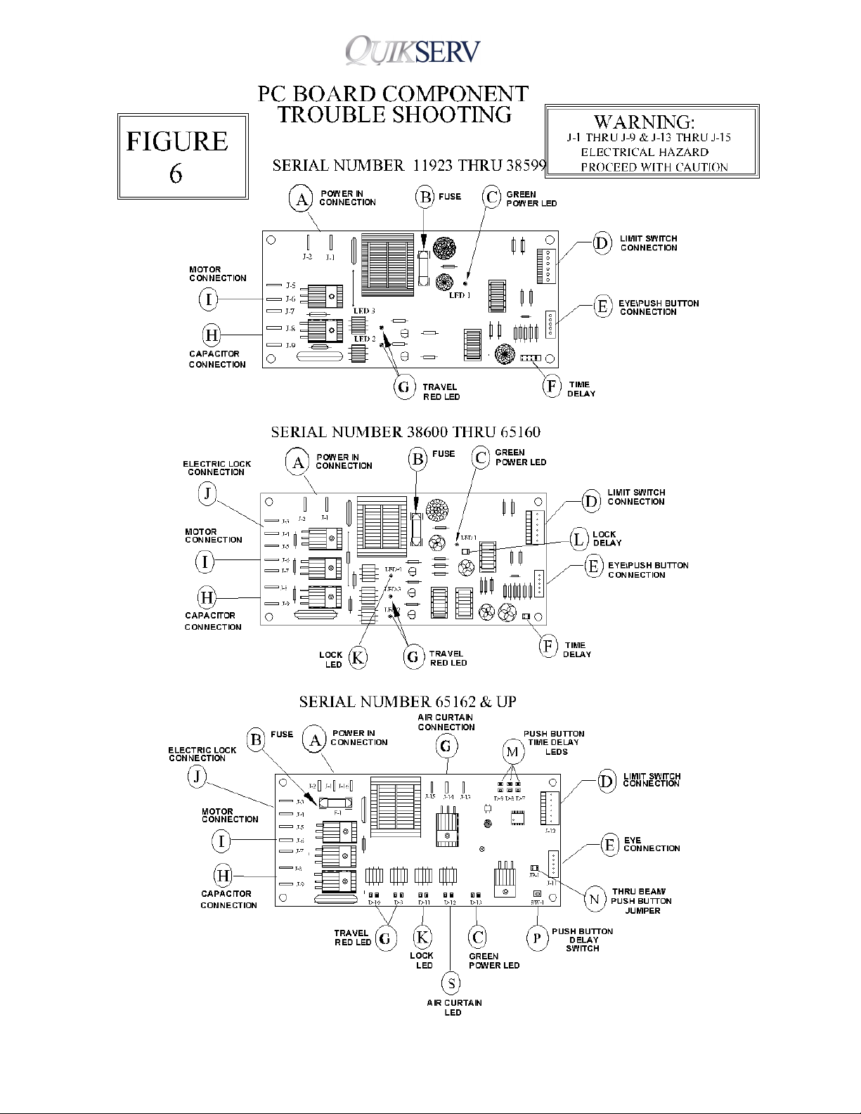
4. Jumper pin not on PC board Install jumper over both pins (Fig. 6-N)
5. Push buon delay not set correct Check me delay lights (Fig. 6-M)
(SEE NOTES BELOW)
Note : If LED 1 is ON the door(s) will close aer 5 sec. (Fig. 6-M)
If LED 2 is ON the door(s) will close aer 15 sec. (Fig. 6-M)
If LED 3 is ON the door(s) will close aer 45 sec. (Fig. 6-M)
To set me delays push delay switch buon (Fig. 6-P) unl desired delay
number 1 (5 sec.) 2 (15 sec.) or 3 (45 sec.) is ON (Fig. 6-M)
Quikserv Corp. quikserv.com
6
• 1-800-388-8307 • Fax (713) 849-5708

Service Manual
Electric Single Sliders
The locaon of the limit switch can be ad-
justed by loosening the two (2) screws in
the bracket and by moving the bracket up
or down in the adjustment slots. When set
properly the switch should clear the ag
bracket by approximately 1/16”. When the
ag bracket is posioned within the
switch, the red LED (open - close) or (LED 2
or 3) Depending on which PC board is in
the unit should be OFF.
Quikserv Corp. quikserv.com
Note: LED2 or LED3 or the (OPEN or
CLOSE) LED lights on the PC Board should
only be “ON” when the doors are moving.
• 1-800-388-8307 • Fax (713) 849-5708
7

Service Manual
Electric Single Sliders
Warning : Turn power switch OFF before
removing access panel.
Component Rack Removal
CAUTION: Power Supply
120Volts
To remove component rack assembly– see
Figure 3 :
1. Unplug power cord from internal outlet.
2. Remove the boom 5-pin connector.
3. Disconnect the ag bracket(s) from the
door bracket.
4. Loosen the (2) 7/16” nuts at each end
of the component rack and slide rack to
the right and liing out.
Quikserv Corp. quikserv.com
Please refer to the TROUBLE SHOOTING
PAGES in this manual for addional infor-
maon on window adjustments or parts
replacement.
Contact us a (800)388-8307 for assis-
tance or for informaon on the nearest
service center in your area.
• 1-800-388-8307 • Fax (713) 849-5708
8

Service Manual
Electric Single Sliders
Quikserv Corp. quikserv.com
• 1-800-388-8307 • Fax (713) 849-5708
9

Service Manual
Electric Single Sliders
Quikserv Corp. quikserv.com
• 1-800-388-8307 • Fax (713) 849-5708
10
Service Manual
Electric Single Sliders
Quikserv Corp. quikserv.com
• 1-800-388-8307 • Fax (713) 849-5708
11

Service Manual
Electric Single Sliders
Quikserv Corp. quikserv.com
• 1-800-388-8307 • Fax (713) 849-5708
12
Service Manual
Electric Single Sliders
Quikserv Corp.© quikserv.com
• 1-800-388-8307 • Fax (713) 849-5708
13

Service Manual
Electric Single Sliders
Quikserv Corp.© quikserv.com
• 1-800-388-8307 • Fax (713) 849-5708
14

Service Manual
Electric Single sliders
Warranty Service Policy
1 Quikserv Corp. MUST be notified of a warranty
situation before any work is performed.
Otherwise, Quikserv Corp. will not be responsible
to pay for unauthorized work.
2. Quikserv Corp. requires the following on each
invoice submitted: an itemized account of work
performed detailing hours charged and parts
used, along with a short detailed description
of the problem noted.
3. Quikserv Corp. will authorize a set dollar
amount to be invoiced prior to performing services
that will be rendered. This amount will
be determined from the initial call to the service
company as a fair maximum. If additional
amounts are to be invoiced, they must be discussed
with Quikserv Corp. prior to invoicing.
4. A service technician on a warranty service call
needs to call our customer service department
at (800) 388-8307 or (713) 849-5882 before
leaving the job site.
5. A service company representative needs to
call the store where the work is to be performed
prior to going to that store. Set up a
parts - either to be sent back or to be kept
by the service technician. Any parts that were
replaced must be returned to Quikserv Corp.
if required verbally or on the service work order
copy supplied with the parts sent by Quikserv
Corp. If the parts are not returned, the
part cost + mark up will be deducted from the
service invoice.
8. A purchase order number will be given either
verbally or on the service work order from
Quikserv Corp. Please use this on all invoicing.
9. Work required on a window unit not covered
under Quikserv’s warranty must be reported
to Quikserv Corp. before work is begun.
10. Quikserv’s payment terms are net 30. The infor-
mation above will help us assure the fastest
and most efficient service possible. For
further information or if you have any questions,
please do not hesitate to contact us at
(800) 388-8307.
Customer Service Department
date and approximate time of arrival and if it
is foreseen that the agreed upon time cannot
be met, contact the store and make other arrangements.
6. Warranty parts sent to service companies are
parts previously decided on that should cover
the necessary repairs. Additional parts will be
sent upon notification to Quikserv Corp
7. Quikserv Corp. needs to be notified of any extra
Quikserv Corp.© quikserv.com
• 1-800-388-8307 • Fax (713) 849-5708
15
 Loading...