

Page 1
Service Manual
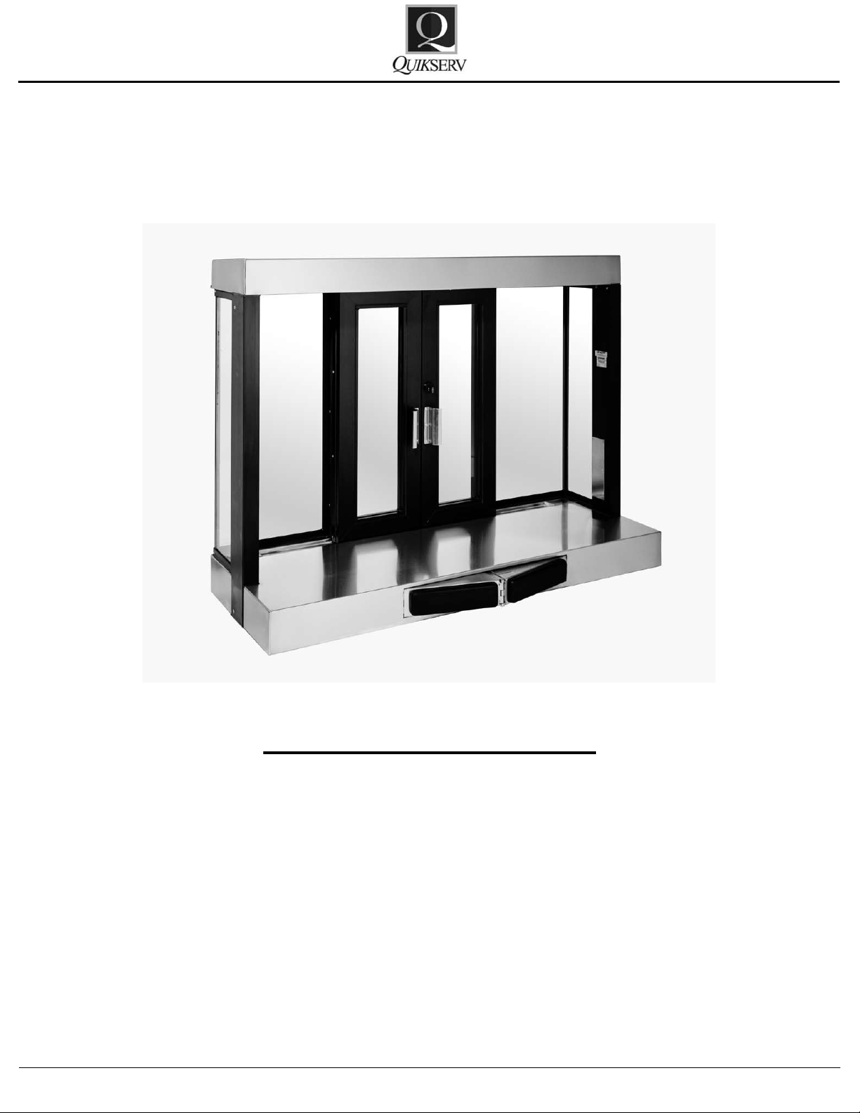
BPS-5440
Semi-Automatic Bi-Parting Sliders
BPS-5440
Click the Procedure to View
Operation and Maintenance Procedure 2
Door Is Not Closing 3
Door Adjustment 4
Slide Rail Adjustment 4
Door Guide Replacement 4
Door Closing Weight Assembly Replacement 5
Push Bar Removal 5
Push Bar Cable Assembly Replacement 6
Push Bar Unit Part List 7
Push Bar Unit Part List Continued 8
Warranty Service Policy 9
Quikserv Corp.© quikserv.com • 1-800-388-8307 • Fax (713) 849-5708
1
Page 2
Service Manual
BPS-5440
Semi-Automatic Bi-Parting Sliders
Operation and Maintenance Procedures
Semi-Automatic Bi-Parting Sliders
Operation and Maintenance Procedures
Pre-Operation Procedures:
• Unlock all locking mechanisms and ensure
that the doors are free of obstructions.
General Cleaning Guidelines:
• All weather-stripping should be checked and
cleaned weekly.
• All glass, aluminum framing, and stainless
steel should be kept clean at all times. All
cleaning uids and applicators should be non-
abrasive.
General Maintenance:
• Slide rail should be kept clean of all dirt and
debris.
• Rails should be oiled with lightweight oil every
6 months.
• Hook lock & thumb turn should be cleaned of
all dirt and debris every 6 months.
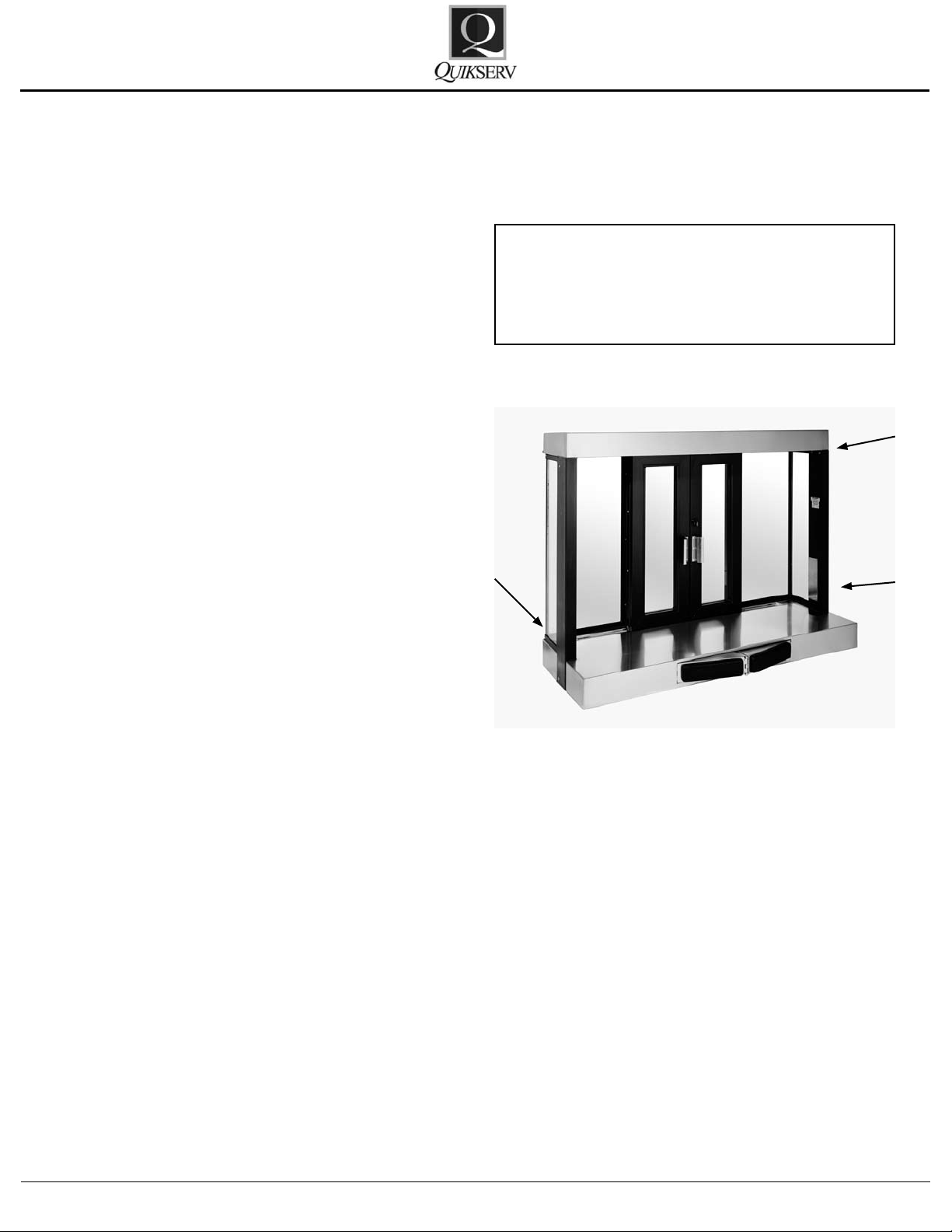
To gain access to the internal components for each window the access panel
must be removed from the exterior of the
window - see arrows below.
To gain access to the internal components for
each window there are 3 access panels that may
need to be removed - see arrows below.
Please refer to the trouble shooting section for
additional information on the window adjustments
or service procedures.
Contact us at (800) 388-8307 for assistance or
for information on the nearest service center in
your area.
Quikserv Corp.© quikserv.com • 1-800-388-8307 • Fax (713) 849-5708
2
Page 3
Trouble Probable Cause Probable Solution
1. Door dra
gging
Adjust door
2. Unit installed out of s
q
uare Contact construction compan
y
3. Door obstructed Remove obstruction
4. Defective slide rail Re
p
lace or oil slide rail
5. Door
g
uide worn out See door guide replacement
6. Wei
g
ht cable broken Cable replacement
7. Push bar obstructed Remove obstruction
8. Push bar cable assemble defective See cable diagram
Door is Not Closing
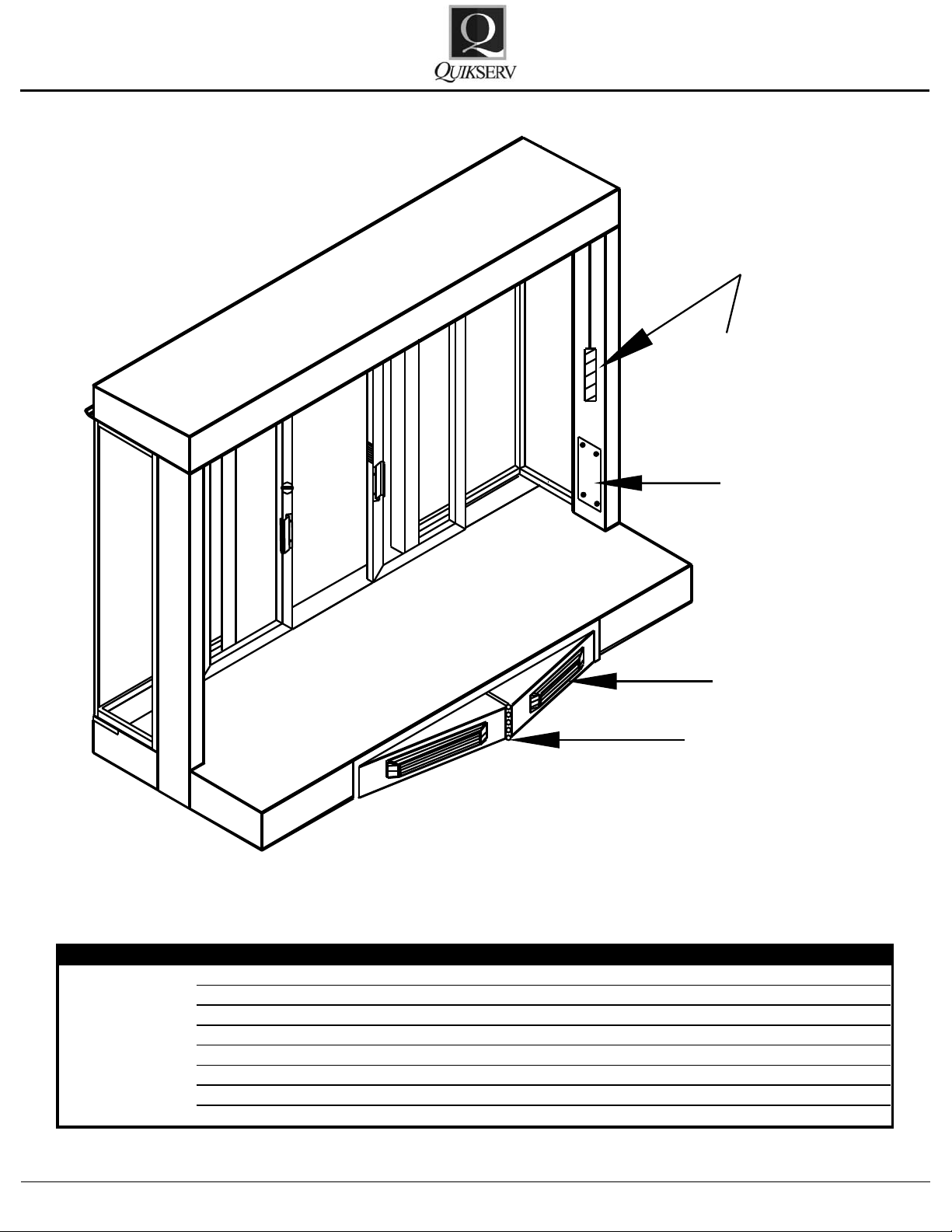
DOOR
WEIGHT
M.
J
K
Service Manual
BPS-5440
Quikserv Corp.© quikserv.com • 1-800-388-8307 • Fax (713) 849-5708
3
Page 4

DOOR
DOOR
F.
DOOR
WEIGHT
D.
C.
A.
A
WEIGHT
PUSH BAR
E
E
DOOR GUIDE PIN
I
EXTRUSION
BOTTOM DOOR
Service Manual
BPS-5440
Part # 1014
Figure 1
Adjustment or Replacement Procedures
Door Adjustment:
1. Loosen the screws on the top of the door holding on the door bracket.
2. Realign the door and tighten the screws using
non-permanent thread-lock.
Slide Rail Replacement:
1. Remove the screws holding the door bracket
2. After removing the doors you now have ac-
3. Install the new slide rail in reverse order that
Quikserv Corp.© quikserv.com • 1-800-388-8307 • Fax (713) 849-5708
to the slide rail.
cess to the screws holding the slide rail to the
header. You may need to slide the rail to the
left or right to gain access to the inner race
screws.
4
it was removed. Use nonpermanent threadlock when replacing the screws.
4. Proper installation height of the door is at the
point where the door is free for movement and
where the weather stripping makes a proper
seal to the stainless steel base.
Door Guide Replacement:
1. Remove the screws holding the door brackets
to the slide rail.
2. Remove the doors.
3. Remove the two screws holding the 2 door
guides to the base. (Part #1014 of Fig I).
4. Replace with new door guide bushings. Reinstall the screws using nonpermanent threadlock.
Page 5

DOOR
DOOR
F.
DOOR
WEIGHT
D.
C.
A.
A
WEIGHT
PUSH BAR
E
E
DOOR
WEIGHT
M.
J
K
B.
E.
A.
D.
B.
CABLE IS 1 PC. CONTINOUS LOOP
V
Service Manual
BPS-5440
Door Closing Weight Assembly
Replacement:
der that it was removed.
8. Apply non-permanent thread-lock on the
weight and all connections.
1. Remove nut from cable connection bracket
(#3869 or Fig. D).
Push Bar Removal:
2. Remove the small access cover panel (Part
#3820 or Fig. M).
3. Drop the cable until the weight reaches the
bottom of the window jamb.
4. Remove weight from the cable.
5. Remove the two screws holding the roller
wheel to the side jamb (Part # 5715 or Fig.
E).
6. Remove the cable and roller assembly.
7. Install new cable assembly in the reverse or-
Quikserv Corp.© quikserv.com • 1-800-388-8307 • Fax (713) 849-5708
1. Remove the hinge pin from the middle of the
push bar assembly – (Part # 1914 or Fig. K)
2. Pull male and female push bar arms apart.
3. Remove the turnbuckle (Part # 5213 or Fig.
V) from the back of the push bar assembly.
4. Remove the two nuts holding the other side of
the push bar assembly to base.
5. Replace in reverse order it was removed.
5
Page 6

SIDE VIEW
S
L
P
N
W
J
A
X
Y
J
z
T
Z
B.
E.
A.
D.
B.
CABLE IS 1 PC. CONTINOUS LOOP
Service Manual
BPS-5440
Quikserv Corp.© quikserv.com • 1-800-388-8307 • Fax (713) 849-5708
Push Bar Cable Assembly Replacement:
1. Remove the nut from push bar cable assembly (Part # 5661 Fig. A) at the cable connection bracket (Part # 3869 or Fig. D).
2. Remove the cable end from the pull cable
swivel (Part # 3319 Fig. T).
3. Remove the cotter pins from the roller brackets (Part # 1032 or Fig. Z).
4. Remove the two screws holding the top push
bar cable assembly to the side jamb (Part #
5661 Fig. A).
5. Remove the entire cable assembly.
6. Replace the cable in the reverse order it was
removed. Note: Ensure that the cable is in-
stalled around the correct rollers.
7. Apply non-permanent thread-lock to all connections.
6
Page 7

Key No. Part No Description
A 5661 Push Bar Cable Assembly
B 5663 Door Bracket Cable Assembly
C 3863 Cable Pinch Bracket
D 3869 Cable Connection Bracket
E 5715 Cable Wheel Assembly
F 1916 Slide Rail
G 2022 Thumb Turn Lock
H 3588 Standard Handle
I 1014 Door Guide
J 2103 Push Bar Pad
K 1914 Hinge Pin
M 3820 Access Cover Plate
N 5655 Push Bar Assembly
A
A
E
E
PUSH BA R
WEIGHT
B
F
D
D
C
CABLE IS 1 PC. CO NTINUOUS LOOP
DOOR DOOR
K
N
J
G
P
U
S
H
B
A
R
P
A
D
S
H
M
DOOR
DOOR
SIDE JAMB
S/S BASE
DOOR
DOOR
DOOR GUIDE PIN
EXTRUSION
BOTTOM DOOR
Service Manual
BPS-5440
Push Bar Unit Part List
I
Quikserv Corp.© quikserv.com • 1-800-388-8307 • Fax (713) 849-5708
7
Page 8

Key No. Part No Description
A 5661 Push Bar Cable Assembly
J 2103 Push Bar Pad
K 1914 Hinge Pin
L 1055 Return Spring
N 3318 Turn Buckle End
P 3321 Actuator Bar
Key No. Part No Description
A 5661 Push Bar Cable Assembly
J 2103 Push Bar Pad
K 1914 Hinge Pin
L 1055 Return Spring
N 3318 Turn Buckle End
P 3321 Actuator Bar
Key No. Part No Description
S 3317 Swivel Block
T 3319 Pull Cable Swivel
W 3702 Spring Bracket
X 1012 Bearing
Y 8020 Spring Ring
Z 1032 Roller Bearing & Roller Wheel
S
L
P
N
W
N
J
J
A
SIDE VIEW
X
Y
Y
Z
T
Z
S/S BASE
J
K
P
U
S
H
B
A
R
P
AD
S
Service Manual
BPS-5440
Push Bar Unit Part List Contiuned
Quikserv Corp.© quikserv.com • 1-800-388-8307 • Fax (713) 849-5708
8
Page 9

Service Manual
Warranty Service Policy
BPS-5440
1. Quikserv Corp. MUST be notied of a warranty situation before any work is performed.
Otherwise, Quikserv Corp will not be responsible to pay for unauthorized work.
2. Quikserv Corp. requires the following on each
invoice submitted: an itemized account of work
performed detailing hours charged and parts
used, along with a short detailed description
of the problem noted.
3. Quikserv Corp. will authorize a set dollar
amount to be invoiced prior to performing services that will be rendered. This amount will
be determined from the initial call to the service company as a fair maximum. If additional
amounts are to be invoiced, they must be discussed with Quikserv Corp. prior to invoicing.
4. A service technician on a warranty service call
needs to call our customer service department
at (800) 388-8307 or (713) 849-5882 before
leaving the job site.
5. A service company representative needs to
call the store where the work is to be performed prior to going to that store. Set up a
date and approximate time of arrival and if it
is foreseen that the agreed upon time cannot
be met, contact the store and make other arrangements.
7. Quikserv Corp. needs to be notied of any extra parts - either to be sent back or to be kept
by the service technician. Any parts that were
replaced must be returned to Quikserv Corp.
if required verbally or on the service work order copy supplied with the parts sent by Quikserv Corp. If the parts are not returned, the
part cost + mark up will be deducted from the
service invoice.
8. A purchase order number will be given either
verbally or on the service work order from
Quikserv Corp. Please use this on all invoicing.
9. Work required on a window unit not covered
under Quikserv’s warranty must be reported
to Quikserv Corp. before work is begun.
10. Quikserv’s payment terms are net 30. The information above will help us assure the fast-
est and most efcient service possible. For
further information or if you have any questions, please do not hesitate to contact us at
(800) 388-8307.
Customer Service Department
6. Warranty parts sent to service companies are
parts previously decided on that should cover
the necessary repairs. Additional parts will be
sent upon notication to Quikserv Corp.
Quikserv Corp.© quikserv.com • 1-800-388-8307 • Fax (713) 849-5708
9
 Loading...