

Page 1
Installation Instructions
By-Pass Regulator
Part No. 30-1899
Thank you for purchasing a Quick Fuel Technology billet pressure regulator with
a by-pass jet. This regulator is intended for use with variable pressure mechanical
fuel pumps.
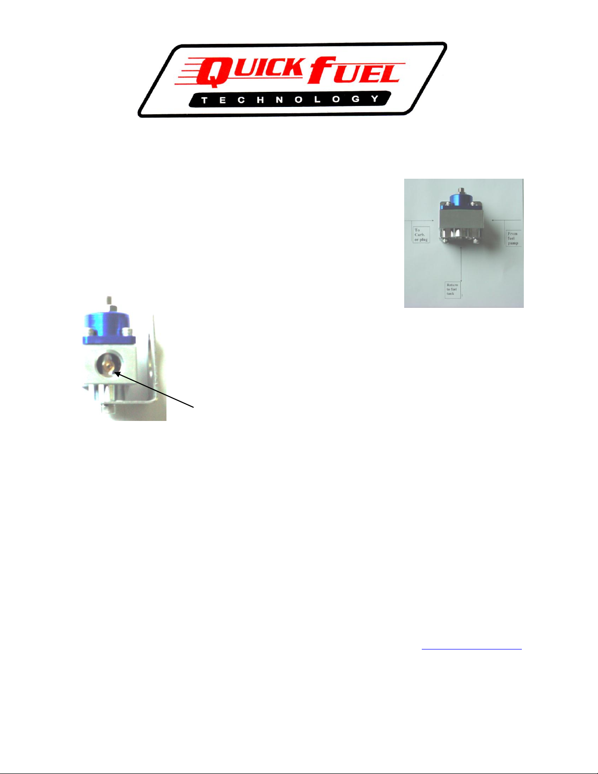
Installation of a by-pass regulator is somewhat different than a conventional “dead
head” regulator. As shown below, the fuel inlet as routed from the fuel pump is
attached to the side port of the regulator. The return line to the tank is routed out
the bottom of the regulator body.
This regulator also has a by-pass jet feature that allows
you to tailor the low speed or low pressure side of your
fuel pump. By changing the by-pass jet you can alter the low side fuel pressure to the
carburetor. As received your regulator is equipped with a #75 jet. This jet is the same as
a conventional gasoline jet for any modular carburetor. The number stamped on the jet is
the equivalent to the standard jet number used for gasoline main jets. Increasing the jet
size will decrease the fuel pressure while decreasing the jet size will decrease the fuel
pressure. A jet number as large as 100, will not materially change the volume or the fuel
pressure of the high side of the fuel pump.
BY-PASS JET ¼-32 THREAD
There are two installation options: 1.) Position the regulator in the conventional location, between the fuel pump and
carburetor. In this case the regulator will be a flow through configuration. 2.) After the carburetor routing is
recommended if at all possible. In this routing the pressure regulator is positioned and act similar to a fuel injection
system. The regulator is mounted behind the carburetor, at the end of your fuel line or fuel log. In this routing, the
end of the fuel line or fuel log is threaded into the side of the regulator body and return line to the fuel tank exits the
bottom of the regulator body. The port opposite the fuel inlet line needs to be plugged. The ports are threaded to
accept a #8 A/N thread. You will need to use a #8 A/N male O-Ring fitting into the regulator body.
The regulator body has a 1/8” NPT to accommodate your fuel pressure gage. In addition, there is a brass barb fitting
also supplied with your regulator that can be used for changing the fuel pressure for applications that uses boost
pressure through the carburetor.
Your regulator is preset to 7 P.S.I. (the high side of the fuel pump output). That is our recommended fuel pressure
for most applications, however one of the benefits of a two stage output fuel pump is to run an elevated pressure
without suffering flooding problems at low RPMs. It is our recommendation not to exceed 9 P.S.I. Should you
need to adjust your fuel pressure loosen the lock nut and turn the adjustment stem with an Allen Wrench. To raise
the fuel pressure turn the stem counter-clockwise. To lower the pressure turn the stem clockwise. After adjusting,
tighten the locknut to prevent the adjustment stem from moving.
129 Dishman Lane, Bowling Green, KY 42101 1-270-793-0900 quickfuel@earthlink.com
P/N 99-38
© Quick Fuel Technology 2005
 Loading...