


SSEW-100D-5V
Quatech SSEW-100D-5V, DSEW-100D-5V, SSEW-400D, SSE-100D, DSE-100D User Manual
...
CONNECT WITH
RELIABILITY
Serial Device Server
User’s Manual
QUATECH, INC.
5675 Hudson Industrial Parkway
Hudson, Ohio 44236-5012
Toll free: 1-800-553-1170
http://www.quatech.com
Quatech Device Server
User’s Manual P/N: 940-0183-155
Manual Revision 1.55

Copyright Copyright © 2006-2008 Quatech, Inc. All rights are reserved. The
information contained in this document cannot be reproduced in any form
without the written consent of Quatech, Inc. Any software programs that
might accompany this document can be used only in accordance with any
license agreement(s) between the purchaser and Quatech, Inc. Quatech,
Inc. reserves the right to change this documentation or the product to
which it refers at any time and without notice.
Trademarks QUATECH® is a registered trademark of Quatech, Inc. Other product
and brand names listed in this manual may be trademarks of their
respective owners.
Disclaimer The information in this manual is believed to be accurate and reliable at
the time of posting. Notwithstanding the foregoing, Quatech assumes no
responsibility for any damage or loss resulting from the use of this
manual, and expressly disclaims any liability or damages for loss of data,
loss of use, and property damage of any kind, direct, incidental or
consequential, in regard to or arising out of the performance or form of
the materials presented herein or in any software program(s) that may
accompany this document.
Changes or modifications to this device not explicitly approved by
Quatech will void the user's authority to operate this device.
Feedback Quatech, Inc. encourages and appreciates feedback concerning this
document. Please send any written comments to the Technical Support
department at the address listed on the cover page of this manual.

Quatech SDS User’s Manual Introduction
Table of contents
Table of contents------------------------------------------------------------------------------------------------------------------ i
Figures ------------------------------------------------------------------------------------------------------------------------ ii
Tables iii
Introduction----------------------------------------------------------------------------------------------------------------------- 1
Understanding how virtual communication ports work-------------------------------------------------------- 2
Understanding MAC and IP addresses and port numbers----------------------------------------------- 2
Identifying operating modes--------------------------------------------------------------------------------------- 3
Identifying Quatech’s SDS product line----------------------------------------------------------------------------- 4
System requirements ----------------------------------------------------------------------------------------------------- 4
Features ---------------------------------------------------------------------------------------------------------------------- 5
Protocol support------------------------------------------------------------------------------------------------------- 5
WiFi implementation------------------------------------------------------------------------------------------------ 6
TCP socket services – IntelliSock™----------------------------------------------------------------------------- 6
Getting started-------------------------------------------------------------------------------------------------------------- 7
Unpacking your SDS ------------------------------------------------------------------------------------------------ 7
Identifying parts ------------------------------------------------------------------------------------------------------ 8
Understanding LED codes ----------------------------------------------------------------------------------------- 9
Locating serial and network ports------------------------------------------------------------------------------10
Making connections------------------------------------------------------------------------------------------------------------13
Enabling WiFi Device Servers----------------------------------------------------------------------------------------------14
Installing the device drivers ------------------------------------------------------------------------------------------------16
Win NT Device Manager------------------------------------------------------------------------------------------------28
Win NT – Changing port numbers -----------------------------------------------------------------------------28
Uninstalling your SDS --------------------------------------------------------------------------------------------------29
Uninstalling from Windows XP/2000 -------------------------------------------------------------------------- 29
Uninstalling from Windows NT4 -------------------------------------------------------------------------------29
Alternative installation steps -----------------------------------------------------------------------------------------30
Configuring the SDS using the Web interface-------------------------------------------------------------------------45
Setting network parameters-------------------------------------------------------------------------------------------47
Setting TCP/IP (LAN) and WiFi (Wireless) parameters -------------------------------------------------47
Setting SNMP parameters----------------------------------------------------------------------------------------52
Viewing the serial port parameters----------------------------------------------------------------------------------55
Setting serial port parameters ----------------------------------------------------------------------------------------55
Setting Normal operating mode parameters ----------------------------------------------------------------55
Setting Tunneling operating mode parameters ------------------------------------------------------------ 58
Setting Raw TCP operating mode parameters--------------------------------------------------------------61
Setting Auto TCP operating mode parameters -------------------------------------------------------------64
Setting Raw UDP operating mode parameters -------------------------------------------------------------68
Running diagnostic tests------------------------------------------------------------------------------------------------73
Using the Port Status screen-------------------------------------------------------------------------------------73
Running the Ping test----------------------------------------------------------------------------------------------73
Checking wireless status------------------------------------------------------------------------------------------ 74
Performing administrative functions -------------------------------------------------------------------------------75
Managing users ------------------------------------------------------------------------------------------------------75
Giving the SDS a descriptive name ----------------------------------------------------------------------------77
Upgrading firmware ------------------------------------------------------------------------------------------------78
April 2008 940-0183-155 Page i

Introduction Quatech SDS User’s Manual
Contacting Quatech ------------------------------------------------------------------------------------------------------79
Troubleshooting and Maintaining an SDS------------------------------------------------------------------------------80
Troubleshooting an SDS ------------------------------------------------------------------------------------------------80
Maintaining an SDS -----------------------------------------------------------------------------------------------------83
Operating conditions -----------------------------------------------------------------------------------------------83
Handling the SDS ---------------------------------------------------------------------------------------------------83
Moving the SDS------------------------------------------------------------------------------------------------------83
Cleaning the SDS---------------------------------------------------------------------------------------------------- 83
Servicing the SDS ---------------------------------------------------------------------------------------------------83
Appendix A -----------------------------------------------------------------------------------------------------------------------84
Specifications---------------------------------------------------------------------------------------------------------------84
Appendix B -----------------------------------------------------------------------------------------------------------------------89
Declaration of Conformity----------------------------------------------------------------------------------------------89
Appendix C -----------------------------------------------------------------------------------------------------------------------91
Warranty information ---------------------------------------------------------------------------------------------------91
Figures
Figure 1 – Connectors and Indicators...................................................................................................... 8
Figure 2 - DB-9 pinouts ..........................................................................................................................10
Figure 3 - RJ-45 pinouts (DB-9 to RJ-45 adapter)................................................................................. 11
Figure 4 - RJ-45 Ethernet port pinout ...................................................................................................12
Figure 5 - Connecting an SDS to a serial device....................................................................................13
Figure 6 - Main Menu screen .................................................................................................................16
Figure 7 - Welcome screen......................................................................................................................17
Figure 8 - Prepare to Install screen .......................................................................................................17
Figure 9 - Search network for Serial Device Server(s) screen...............................................................18
Figure 10 - Where is the Serial Device Server attached screen............................................................19
Figure 11 - Network Connectivity Test screen ......................................................................................20
Figure 12 - Retrieving Unit Configuration pop-up box..........................................................................20
Figure 13 - TCP/IP Network Configuration Parameters screen ...........................................................21
Figure 14 - Internet Protocol (TCP/IP) Properties dialog box ...............................................................22
Figure 15 - Restart confirmation pop-up box.........................................................................................23
Figure 16 - Information pop-up box .......................................................................................................23
Figure 17 - TCP/IP Network Configuration Parameters screen ...........................................................24
Figure 18 - Rerun network connectivity test pop-up box ...................................................................... 24
Figure 19 - Network Connectivity Test screen ......................................................................................25
Figure 20 - Retrieving Unit Configuration pop-up box..........................................................................25
Figure 21 - TCP/IP Network Configuration Parameters screen ...........................................................26
Figure 22 - Install the Device Drivers screen ........................................................................................26
Figure 23 - Installation Complete screen...............................................................................................27
Figure 24 - Reconfigure the Serial Device Server screen ......................................................................30
Figure 25 - Serial Device Server is Configured for a Remote Subnet...................................................31
Figure 26 - Internet Protocol (TCP/IP) Properties dialog box ...............................................................32
Figure 27 - Restart confirmation pop-up box.........................................................................................33
Figure 28 - Information pop-up box .......................................................................................................33
Figure 29 - TCP/IP Network Configuration Parameters screen ...........................................................34
Figure 30 - Rerun network connectivity test pop-up box ...................................................................... 34
Figure 31 - DHCP confirmation pop-up box...........................................................................................35
Figure 32 - SDS Wizard Information DHCP screen .............................................................................. 35
Page ii 940-0183-155 April 2008

Quatech SDS User’s Manual Introduction
Figure 33 - Locate the Serial Device Server screen............................................................................... 36
Figure 34 - Locate the Serial Device Server using direct discovery screen .......................................... 37
Figure 35 - Locate the Serial Device Server on a remote subnet screen...............................................38
Figure 36 - Describe the Remote Subnet screen....................................................................................39
Figure 37 - Locate the Serial Device Server options screen.................................................................. 40
Figure 38 - Locate the Serial Device Server local discovery screen........................................................41
Figure 39 - Select Desired Serial Device Server from list screen.......................................................... 42
Figure 40 - Specify IP Address screen....................................................................................................43
Figure 41 - Network Connectivity Test Failed screen........................................................................... 44
Figure 42 - Home page screen ................................................................................................................46
Figure 43 - Network Setup screen..........................................................................................................48
Figure 44 - IP Address Successful screen ..............................................................................................51
Figure 45 - Remote Reset screen............................................................................................................ 51
Figure 46 - SDS is now resetting screen ................................................................................................51
Figure 47 - SNMP Setup screen............................................................................................................. 52
Figure 48 - SNMP Address Update Successful screen .......................................................................... 54
Figure 49 - Remote Reset screen............................................................................................................ 54
Figure 50 - SDS is now resetting screen ................................................................................................54
Figure 51 - Serial Port Status screen.....................................................................................................55
Figure 52 - Serial Port Setup screen for Normal mode ......................................................................... 56
Figure 53 - Serial Port Setup screen for Tunneling mode..................................................................... 59
Figure 54 - Serial Port Setup screen for Raw TCP mode ......................................................................62
Figure 55 - Serial Port Setup screen for Auto TCP mode......................................................................66
Figure 56 - Serial Port Setup screen for Raw UDP mode......................................................................70
Figure 57 - Port Status screen................................................................................................................73
Figure 58 - Ping Test screen...................................................................................................................73
Figure 59 - Ping results screen...............................................................................................................74
Figure 60 – Wireless Status screen........................................................................................................ 74
Figure 61 - Show Users screen............................................................................................................... 75
Figure 62 - Add/Del Users screen........................................................................................................... 76
Figure 63 - Network confirmation prompt.............................................................................................76
Figure 64 - Add/Del Users screen........................................................................................................... 77
Figure 65 - Show Users screen............................................................................................................... 77
Figure 66 - Set Descriptive Name screen...............................................................................................77
Figure 67 - Firmware Upgrade screen ...................................................................................................78
Figure 68 - Remote Reset .......................................................................................................................78
Figure 69 - Contact Us screen ................................................................................................................79
Tables
Table 1 - SDS models................................................................................................................................4
Table 2 - SDS LED codes..........................................................................................................................9
Table 3 - RS-232 signals on DB-9 connector .......................................................................................... 10
Table 4 - RS-422/485 signals on DB-9 connector ...................................................................................10
Table 5 - RS-232 signals on RJ-45 connector (DB-9 to RJ-45 adapter).................................................11
Table 6 - RS-422/485 signals on RJ-45 connector (DB-9 to RJ-45 adapter)..........................................11
Table 7 - RJ-45 Ethernet port signals.................................................................................................... 12
Table 8 - Class A, B, and C address masks............................................................................................ 49
Table 9 - Complete list of address masks...............................................................................................49
April 2008 940-0183-155 Page iii

Introduction Quatech SDS User’s Manual
This page intentionally left blank.
Page iv 940-0183-155 April 2008

Quatech SDS User’s Manual Introduction
A
Introduction
Quatech’s line of Serial Device Servers (SDS) is designed to networkenable any device currently using RS-232 or RS-422/485 serial
communications protocols. Our Device Servers provide industryleading hardware and user-friendly software to make connecting your
serial devices to an Ethernet network a surprisingly simple process.
There are many reasons to network your serial devices using a
Quatech Device Server, such as:
Note: For on-line technical
support, see Quatech’s Web site.
A typical scenario:
You have a serial device
that is operated by a PC.
The application software on
the PC “talks” to the serial
device using COM port 3.
Unfortunately, anyone who
wants to communicate with
that device must come to the
local PC. This can be very
time consuming if the serial
device is located in a remote
area, and expensive if you
need a PC for every serial
device.
Device Server eliminates
the need for a local PC and
allows anyone with the
proper application software,
the Quatech Device Server
drivers, and authorized
access to the network, to
communicate with the serial
device.
¾ Remote support – support personnel can diagnose and repair
many problems by communicating with your serial devices via the
Internet or Intranet.
¾ Remote management – install new firmware or software upgrades
on your serial devices without physically removing them from
service.
¾ Efficient communications – instead of having one device
communicating with one computer, your device can communicate
with any computer on the network.
¾ Wireless freedom – WiFi-enabled Device Servers provide serial-
to-wireless connectivity to your network.
¾ Lower cost of ownership – no need to upgrade serial devices to
newer, costlier versions containing built-in Ethernet interfaces –
if such an upgrade is even available!
¾ Extended service life of software – your existing software can be
used to communicate with the serial device as if connected to a
local COM port; the network connection is “invisible” to the
application.
After following the simple steps included in the Quick Start Guide to
attach your network and serial devices to the appropriate connectors
on the Serial Device Server, you’ll need just a few more minutes to
install the driver. You’ll then be able to communicate with the serial
device via its own application software and with the SDS using a Web
browser!
To network-enable a serial device, plug it into the serial port located
on the Device Server. Plug in the network Ethernet cable and power
source, and load the Quatech device drivers onto a host PC anywhere
on the network, using the instructions provided. The Quatech device
drivers will install the SDS’ serial ports as if they were additional
local COM ports in Windows. Simply change the settings in the serial
device’s application software to look for the serial device on the new
COM port. It’s that easy!
April 2008 940-0183-155 Page 1

Introduction Quatech SDS User’s Manual
r
Understanding how virtual communication ports work
Note: Quatech Device Server
technology now allows access
to individual serial devices by
anyone with access to the
network on which they are
installed.
Note: Anyone in your organization
with a PC can connect to the
serial device over the network
just as though the two devices
were directly connected.
Note: A protocol is a set of rules
that notifies a transmitting
device and a receiving device
that the other is present and
ready to exchange information,
when the exchange is complete,
and whether it was successful.
Single port Device Servers allow you to network individual serial
devices such as printers, simple terminals, or medical monitoring
equipment that were previously accessible only via a direct link.
According to Dataquest, a Device Server is a “specialized networkbased hardware device designed to perform a single or specialized set
of functions with client access independent of any operating system or
proprietary protocol.” In terms of your new SDS, this means that you
can connect any serial device to your network by connecting the serial
device to a serial port on your SDS and connecting the Ethernet port
on your SDS to your network.
The SDS, once it has been correctly configured, makes accessing a
single serial device such as a time clock from your network a
transparent operation. This means that a PC can perform all the
operations in the same way it would if the serial device were plugged
directly into its serial port.
A network connection allows operation of serial devices at much
greater distances than can be accomplished with a direct serial
connection. Your SDS uses the TCP/IP protocol suite for network
communications. This means that communication through an SDS
can actually be more reliable than communication over long serial
lines, which lacks the advanced error checking built into TCP/IP.
Another benefit of accessing a serial device through an SDS is that
you can monitor and manage the device remotely, even from across
the world, if you have authorization and the network connection is to
the Internet.
Understanding MAC and IP addresses and port numbers
Identifying the Ethernet (MAC) address
Note: You can find the unit’s
Ethernet (MAC) address on the
product information label
located on the bottom of the
unit.
Assigning an IP address
Ethernet address, hardware address, and MAC address are all
equivalent names for a device’s unique network address. In the case
of an SDS, the first three bytes identify the unit as a Quatech
product. The last three bytes are unique to each unit and are
assigned when the unit is released from production. Colons separate
the bytes. The following is an example of an SDS Ethernet (MAC)
address:
00:0B:28:12:34:56
Quatech’s Unique product
unique identifie
Every device that communicates over the Internet must have a
unique IP address. You can assign an IP address to your SDS by
either of two methods:
¾ Through the Installation Wizard for initial configuration
¾ Through the Web interface for reconfiguration and maintenance
identifier
Page 2 940-0183-155 April 2008

Quatech SDS User’s Manual Introduction
Using Port numbers
Note: You can think of the IP
address as a telephone number
and the port number as a
telephone extension.
Note: This information is
useful for firewall configuration.
Identifying operating modes
Normal mode
Note: Normal is the standard
connection mode for an SDS.
Tunneling mode
In order for devices to communicate via a TCP connection or a UDP
datagram, they must know each other’s IP address and port number.
The SDS driver automatically sets the unit’s port number for you.
A specific port number identifies each SDS serial port. An SDS
assigns a port number of 5000 to the first port and then increments
the port number sequentially for each subsequent serial port. SDS
drivers must see the first port as IP address: 5000.
Normal, Tunneling, Raw TCP, Auto TCP, and Raw UDP are all
different schemes to make a serial connection across a network using
one or more Serial Device Servers.
If you use Quatech’s virtual COM port drivers or the IntelliSock™
SDK (see TCP socket services – IntelliSock™ on page 6), you should
use the Normal mode to make your network connections. Normal
mode is used in the vast majority of applications. Unless you are
certain that you need to use a different mode, go ahead and configure
your SDS in Normal mode. This mode allows for complete software
control of the serial port by an application program.
Note: In Tunneling, a master
sends out the configuration
information to a slave so that
the slave can communicate
with it.
Raw TCP mode
Note: You could use Raw TCP
if you were running a simple,
custom TCP application.
Auto TCP mode
Note: Auto TCP is the only
communication mode that lets
an SDS initiate the connection.
Serial Tunneling allows two Device Servers and their Ethernet
TCP/IP connection to act like a direct cable connection between two
serial devices. No host computer is required.
Tunneling is very simple to use. Use the SDS’ web interface to
designate one SDS serial port as the tunneling master and the other
SDS port as the tunneling slave. Configure the master with the serial
port settings desired for the connection as well as the IP address of
the tunneling slave. The master makes the connection and automatically
configures the slave with the corresponding settings.
In Raw TCP mode, serial port data travels over the TCP/IP
connection without any protocol wrapper. You must configure the
serial port settings using the SDS’ web interface. Raw TCP mode
works with most third party universal serial device server drivers.
Auto TCP mode is a special case of Raw TCP mode that allows the
SDS to act as a network client and to initiate a TCP connection to a
network host. You can configure the SDS so that it makes the
connection in one of two possible instances:
¾ It receives serial data (Data mode).
¾ It sees that the DSR input is active (DSR mode).
As with Raw TCP mode, you must configure the serial port settings
using the SDS’ web interface. You must configure the SDS with the
April 2008 940-0183-155 Page 3

Introduction Quatech SDS User’s Manual
IP address and TCP port number of the network host to which it
should connect. If the SDS is idle, it will listen for normal Raw TCP
mode connections from the network host.
Raw UDP mode
Note: Raw UDP can provide
one-to-many communications.
Raw UDP is used primarily for broadcasting messages over a network.
It is lightweight and efficient; however, your application program
must handle all error processing and retransmission. Quatech
supports the following modes of UDP communication:
¾ Multicast (transmits to specified group of recipients)
¾ Broadcast (transmits to unspecified recipients)
¾ Point-to-Point (transmits to one recipient)
Identifying Quatech’s SDS product line
Quatech provides a family of SDS products. SSE-100, DSE-100, QSE100, and ESE-100 provide one, two, four, and eight RS-232 ports for
your serial devices, respectively. SSE-400, DSE-400, QSE-400, and
ESE-400 allow you to software-select between RS-232 and RS422/485 communications. For convenience, this manual refers to all
these products as SDS unless otherwise noted.
Table 1 - SDS models
Note: All models are available
with surge suppression as an
–SS option. For example, the 4port RS-232 unit with DB-9
connectors and surge suppression
would have a part number of
QSE-100D-SS.
RS-232
Device
Ports
SSE-100 1 SSE-400
DSE-100 2 DSE-400
QSE-100 4 QSE-400
ESE-100 8 ESE-400
RS-232/422/485
Device
Note: SDS products with a “W”
in their part numbers (such as
SSEW-100) implement WiFi
technology. They provide serialto-wireless communications in
addition to all standard SDS
functions.
Quatech’s SDS products all perform the same function (see notes),
differing mainly in the number of serial ports available or in the
serial protocol supported. All “D” models, which add a suffix of D to
the part number, (e.g. SSE-100D) are supplied with DB-9 connectors.
All “M” models, which add a suffix of M to the part number, (e.g.
QSE-100M) are supplied with 10-pin RJ-45 adapters that attach to
the DB-9 connectors.
System requirements
Quatech’s SDS ships with device drivers for Windows 2000, Windows
NT4, Windows XP, and Linux. Other operating systems can access
the SDS using Raw TCP mode or the IntelliSock™ TCP socket
services. Quatech will provide reference materials and utilities to
assist those who wish to do so.
Contact our sales department for details on current software
offerings. Most device drivers are available for download from the
Quatech World Wide Web site at http://www.quatech.com/
Page 4 940-0183-155 April 2008
.

Quatech SDS User’s Manual Introduction
Features
Quatech Device Servers can connect virtually any serial device to any
Note: Quatech Device Servers
capture data from legacy serial
devices without having to go
through a PC.
Protocol support
standard Ethernet network (Intranet or Internet) using TCP/IP
protocols. The following list details some of the serial devices an SDS
can bring to your fingertips:
¾ Security system alarm/access control devices
¾ Industrial computers and sensors
¾ Point-of-Sale (POS) peripherals
¾ Time clocks
¾ Banking peripherals and ATM machines
¾ Medical equipment
The SDS communicates over an Ethernet network using the standard
IP and TCP protocols to ensure data integrity and accurate targeting.
An SDS supports the following protocols:
¾ Network addressing, routing, and data block handling: IP
¾ Network communications: TCP, UDP, DHCP, HTTP, and ARP
¾ Network management: SNMP
SNMP Network management support
The Simple Network Management Protocol (SNMP) agent running on
Note: Only SDS devices with a
firmware revision level of 5.0
and above can support SNMP.
To determine the revision level
of an SDS, check the bottom of
the Home page in the Webbased interface (see page 43).
your SDS collects network statistics such as the amount of data
transmitted and received, the number of frames that contain errors,
and the speed of the interface.
A network management system consists of these four parts:
¾ Network manager – One or more workstations used to monitor
¾ Managed system – Composed of managed devices on the network
¾ Management Information Base (MIB) – Standard organization
Note: SNMP is used to
communicate status updates
and parameter values between
a remote device such as an
SDS and a network manager.
¾ Network management protocol – SNMP is a set of rules governing
The SDS supports MIB II, which is a standard set of statistics. It
includes information on system interfaces, address translation, IP,
ICMP, TCP, UDP, transmission, and SNMP group information.
Note: The SDS is a read-only
device. You cannot set any
parameters via SNMP.
For example, the agent running on the SDS collects network statistics
including the amount of data transmitted and received, the number of
frames that contain errors, the percentage of utilization of the
network, maximum packet size, speed, MAC address, and whether
the device is up and working. The agent provides a whole tree of
and manage the elements comprising a network
running the agent process, such as an SDS
scheme for storing data records; an SDS device with a firmware
revision of 5.0 and above supports MIB-II
the exchange of management information between a network
manager and the elements of a managed system
April 2008 940-0183-155 Page 5

Introduction Quatech SDS User’s Manual
Note: Traps are messages or
alarms generated by an SNMP
agent to indicate to the SNMP
manager that a significant
event has occurred.
WiFi implementation
Note: WiFi is a wireless Ethernet
communication option.
Note: To setup the Wireless
SDS, you must first connect to
it in wired Ethernet mode to
obtain the IP address. Then,
use the Web browser to
configure the network settings
for WiFi communications.
See Enabling WiFi Device
Servers on page 14 for details
on installing and configuring
your wireless SDS.
information that a management network host can retrieve using the
Get command.
In addition to providing information upon request, the SDS supports
a cold start Trap, which is a spontaneous message the SDS initiates
whenever it boots up.
WiFi, short for wireless fidelity, allows WiFi-enabled devices to
connect to an Ethernet/Internet network without cables or wires. You
can use a WiFi network to connect these devices to each other, to the
Internet, and to wired networks. WiFi is a fast, powerful, reliable,
and secure alternative to wired communication.
Quatech’s WiFi-enabled SDS devices provide serial-to-wireless
network connectivity. They enable you to connect to and communicate
with your serial devices over 802.11b/g wireless networks. These
units all have a “W” incorporated in their names, such as SSEW-100
or DSEW-400.
There are two access modes you can use with your WiFi SDS,
depending on whether or not an access point (AP) is involved.
¾ Infrastructure uses an access point to link the SDS to other
network devices.
For example, an SDS connected to a POS device by a serial cable
will send and receive POS data through an AP to a wireless
network. Any PC connected to that network (either by a wired
connection or via an AP) can communicate directly with the POS
device. Optional WEP and WPA security protocols can encrypt
data to protect it during transmission from the SDS to an AP.
¾ Ad hoc directly links a SDS with another device without going
through an access point. For example, if you connect a security
camera’s serial port to an SDS, a wireless PC can connect directly
to the security camera through the SDS without ever going
through an AP.
Before an SDS can communicate on an 802.11b/g wireless network,
the WLAN settings must match those of the wireless network. By
default, an SDS is set to Infrastructure network mode and its
wireless Network Name (SSID) is blank, which will allow it to
connect to any available wireless network.
TCP socket services – IntelliSock™
Note: Quatech’s IntelliSock™
provides the most flexible and
powerful TCP socket services
available for custom applications.
Note: If you do not need the
power of the IntelliSock interface,
the Raw TCP mode provides a
simple way of using a direct
TCP connection with the SDS.
Page 6 940-0183-155 April 2008
The SDS implements Quatech’s IntelliSock™ TCP socket services.
Quatech supplies device drivers for Windows 2000, NT4, XP, and
Linux to make the SDS look like it is a built-in COM port.
IntelliSock offers you the option of interfacing directly to the SDS
through a TCP socket programming interface rather than using the
virtual COM port device drivers. IntelliSock can be used with any
operating system that supports TCP/IP communication.
Refer to the IntelliSock Software Developer’s Kit (SDK) folder on the
installation CD-ROM for documentation and sample code.

Quatech SDS User’s Manual Introduction
Getting started
Unpacking your SDS
Follow these steps to unpack your SDS.
Step Procedure Description
Step 1 Remove the SDS from the box.
Step 2 Remove all packing material from the SDS. Save the packaging in case you ever need
to store the unit or return it to Quatech
for service.
Step 3 Check the contents of the package to make
sure you have received everything listed
below:
¾ SDS
¾ Power cable
¾ Power source
¾ Loopback connector(s)
¾ CD-ROM containing the SDS device
drivers and configuration software
¾ Quick Start Guide
Step 4 Check the SDS and accessories for shipping
damage.
The complete SDS package ships in a
single box.
Pay particular attention to the SDS’ case
and port connectors. If anything is
missing or damaged, contact your
Quatech sales representative.
April 2008 940-0183-155 Page 7
Introduction Quatech SDS User’s Manual
Identifying parts
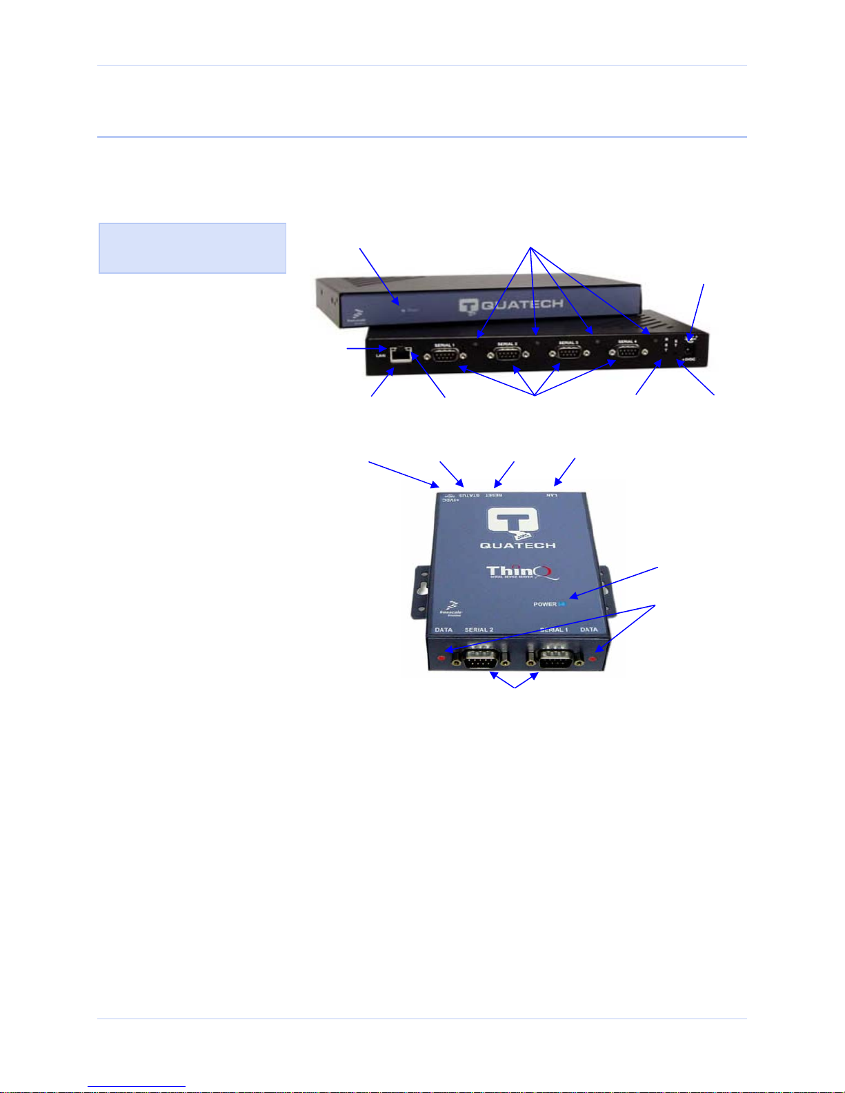
Figure 1 shows the connectors and indicator lights (LEDs) of the SDS.
See below for a description of each item shown.
Figure 1 – Connectors and Indicators
The actual number and
location of serial ports will
vary according to the model.
Power LED Data LEDs
Powerjack
Speed LED
Link LED Reset button Status LED
Serial portsEthernet jack
Power jack
Status LED
Reset button
Speed LED
Link LED
Ethernet jack
The SDS has several indicator LEDs:
¾ Power (blue) – indicates when the SDS has line power
¾ Data (red/green) – indicates serial port data activity by blinking red for RS-232 or green for RS-422/485
¾ Status (green) – indicates when the embedded processor is up and running
¾ Link (green) – indicates when a network link has been established; located in the Ethernet connector
¾ Speed (amber) – differentiates between 100Base-T (glowing) and 10Base-T (off) Ethernet connection speeds; located in
the Ethernet connector
The DB-9 serial port(s) connect to your serial device(s) and can support RS-232, RS-422, or RS-485 connections. They are
located either to the left, to either side of the Ethernet port, or on the front panel, depending on the model.
The RJ-45 Ethernet jack connects the SDS to the Internet or to your Intranet. It has two small status LEDs: Link (green) and
Speed (amber).
The power jack should be connected to a +5V power source, as provided with the SDS.
The Reset button puts the SDS through a reset cycle and can also restore the SDS to the factory default settings.
The information label (not shown) is on the bottom of the SDS. It includes the following:
¾ MAC address
¾ Serial number
¾ Certifications
¾ Pinout diagram
Serial ports
Power LED
Data LEDs
Page 8 940-0183-155 April 2008

Quatech SDS User’s Manual Introduction
p
Understanding LED codes
The SDS LEDs inform you of the communications status and activity
of the SDS. The following table lists the possible states of the LEDs
and their meaning.
Table 2 - SDS LED codes
LEDs Meaning
Link (green) On steady = connected to network
On steady for WiFi SDS units:
¾ Infrastructure = SDS is
associated with Access Point
¾ Ad hoc = SDS has found
device to communicate with
Note: If you press and
immediately release the Reset
button, the SDS restarts
automatically with no changes.
Also, if you continue holding
the Reset button longer than 20
seconds, the Status LED stops
flashing and no changes are
made.
Speed (amber)
Off = 10 Mbps network connection
established if Link LED is on
On steady = 100 Mbps network
connection established
Data (red/green) Red = RS-232 connection
Green = RS-422/485 connection
Blinking = data activity
Status (green)
On = SDS is up and running
The Status LED also works in
conjunction with the Reset button
as follows:
1. To restore the SDS to the
factory default configuration,
push in and hold the Reset
button. When the Status LED
starts flashing slowly, and
before it starts flashing
rapidly, release the button.
The SDS then restarts
automatically.
2. To restore the SDS to the
factory default firmware
revision, push in and hold the
Reset button. When the Status
LED changes from a slow flash
to a rapid flash, release the
button. The SDS then restarts
If the Reset button is held during
the first 10 seconds of bootup, the
Status LED flashes at a rate of 1
flash every 2 seconds for 10
seconds. If the button is released
during this time period, the
configuration is reset to factory
defaults.
If the Reset button is held past the
first 10 seconds of bootup, the LED
flashes faster at a rate of 1 flash
every second for 10 seconds. If the
button is released during this time
eriod, the SDS is reset back to the
factory default firmware revision.
automatically.
April 2008 940-0183-155 Page 9
Introduction Quatech SDS User’s Manual
Locating serial and network ports
Serial port(s)
Note: The location of the serial
port(s) varies, depending on
the model.
Figure 3 and Tables 3 and 4
show the RS-232/422/485
DB-9 pinouts and signal
descriptions.
SDS serial ports connect via cables to your serial device(s). The
number of these ports will vary depending on the SDS model. All SDS
models come with DB-9 serial port connectors. RS-232 “M” models
include adapter plugs to convert the DB-9 connectors to RJ-45
connectors. See Making connections on page 13 for directions on
connecting an SDS serial port to a serial device.
The following figures and tables show the serial port pinouts for RS232 and RS-232/422/485 applications.
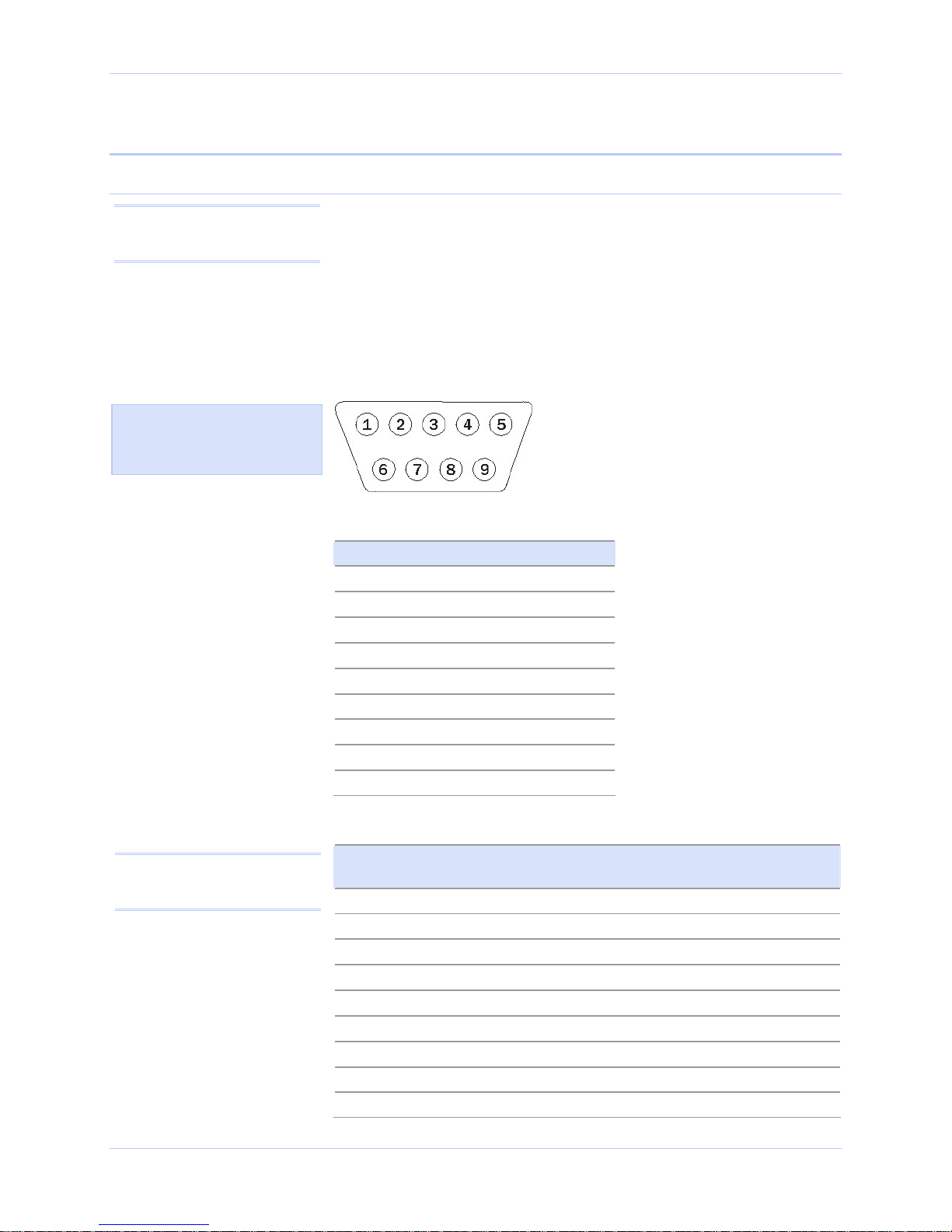
Figure 2 - DB-9 pinouts
Table 3 - RS-232 signals on DB-9 connector
RS-232 signal description DB-9
Data Carrier Detect (DCD) 1
Receive Data (RxD) 2
Transmit Data (TxD) 3
Data Terminal Ready (DTR) 4
Signal Ground (GND) 5
Data Set Ready (DSR) 6
Request To Send (RTS) 7
Clear To Send (CTS) 8
Ring Indicator (RI) 9
Note: Pins labeled NC are
indeterminate in two-wire mode
and should be left unconnected.
Page 10 940-0183-155 April 2008
Table 4 - RS-422/485 signals on DB-9 connector
RS-422/485 signal description
four-wire mode
Auxiliary Input (AuxIn–) 1 NC
Receive Data (RxD+) 2 NC
Transmit Data (TxD+) 3 Transmit/Receive Data (Data+)
Auxiliary Output (AuxOut–) 4 NC
Signal Ground (GND) 5 Signal Ground (GND)
Receive Data (RxD–) 6
Auxiliary Output (AuxOut+) 7
Auxiliary Input (AuxIn+) 8
Transmit Data (TxD–) 9 Transmit/Receive Data (Data–)
DB-9 RS-422/485 signal description
two-wire mode
NC
NC
NC
Quatech SDS User’s Manual Introduction
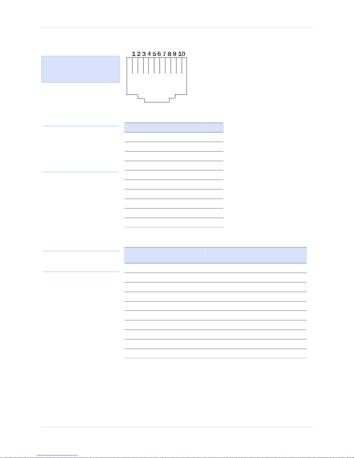
Figure 3 - RJ-45 pinouts (DB-9 to RJ-45 adapter)
Figure 4 and Tables 5 and 6
show the RS-232/422/485
-RJ-45 pinouts and signal
descriptions.
Table 5 - RS-232 signals on RJ-45 connector (DB-9 to RJ-45 adapter)
Note: If your serial port cable
uses an 8-pin RJ-45 plug, you
can use the center eight pins of
the SDS’ RJ-45 connector for
RS-232 communications. You
will lose access to the Ring
Indicator signal.
Note: Pins labeled NC are
indeterminate in two-wire mode
and should be left unconnected.
RS-232 signal description RJ-45
Ring Indicator (RI) 1
Request To Send (RTS) 2
Data Terminal Ready (DTR) 3
Signal Ground (GND) 4
Transmit Data (TxD) 5
Receive Data (RxD) 6
Data Carrier Detect (DCD) 7
Data Set Ready (DSR) 8
Clear To Send (CTS) 9
No Connection 10
Table 6 - RS-422/485 signals on RJ-45 connector (DB-9 to RJ-45 adapter)
RS-422/485 signal description
four-wire mode
Transmit Data (TxD–) 1 Transmit/Receive Data (Data–)
Auxiliary Output (AuxOut+) 2
Auxiliary Output (AuxOut–) 3
Signal Ground (GND) 4 Signal Ground (GND)
Transmit Data (TxD+) 5 Transmit/Receive Data (Data+)
Receive Data (RxD+) 6
Auxiliary Input (AuxIn–) 7
Receive Data (RxD–) 8
Auxiliary Input (AuxIn+) 9
No Connection 10 No Connection
RJ-45 RS-422/485 signal description
two-wire mode
NC
NC
NC
NC
NC
NC
April 2008 940-0183-155 Page 11
Introduction Quatech SDS User’s Manual
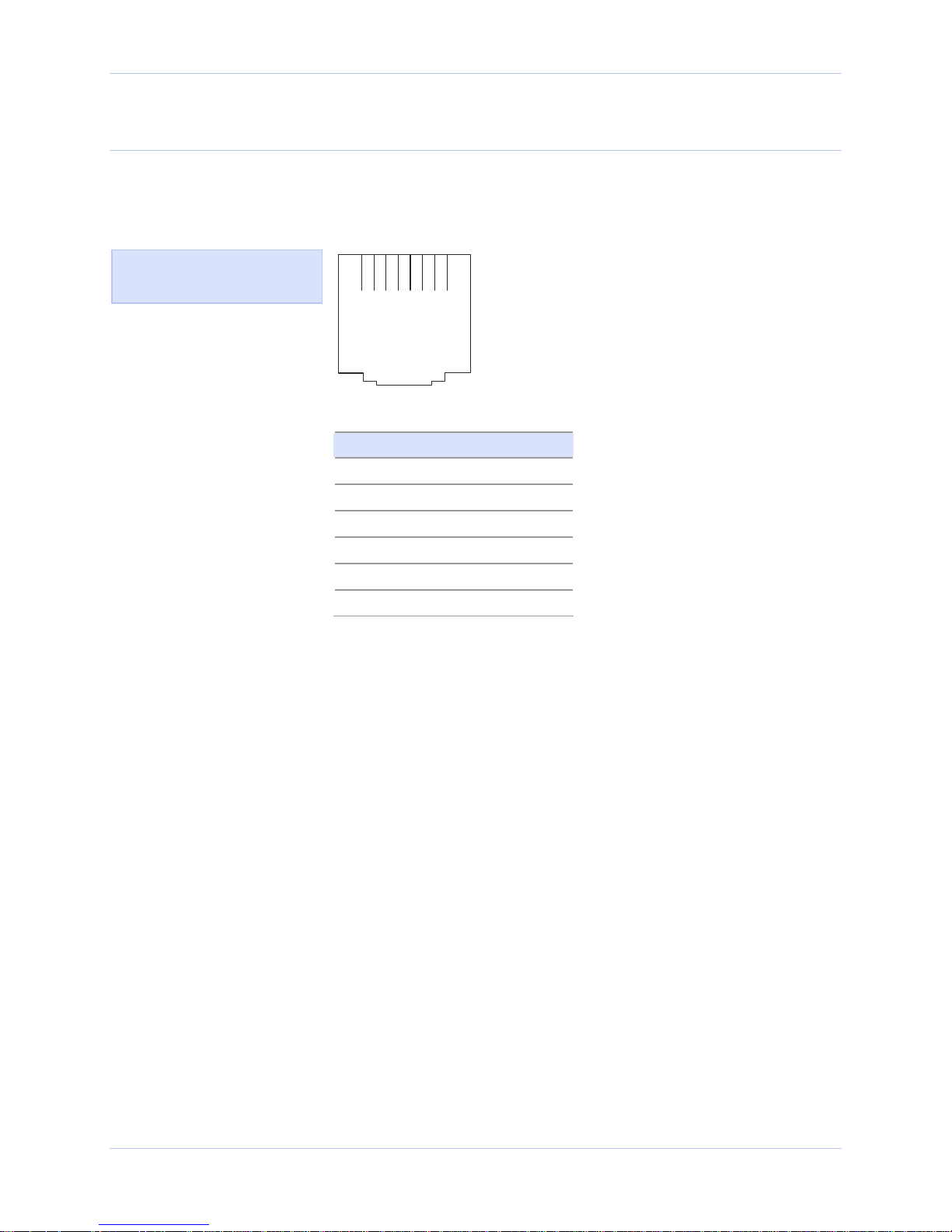
Network port
All SDS devices have one eight-pin RJ-45 Ethernet port on the back
panel.
Figure 4 - RJ-45 Ethernet port pinout
Figure 5 and Table 7 show the
Ethernet RJ-45 pinouts and
signal descriptions.
1 2 3 4 5 6 7 8
Table 7 - RJ-45 Ethernet port signals
Ethernet signal description RJ-45
Transmit Data (TxD+) 1
Transmit Data (TxD–) 2
Receive Data (RxD+) 3
No connection 4, 5
Receive Data (RxD–) 6
No connection 7, 8
Page 12 940-0183-155 April 2008
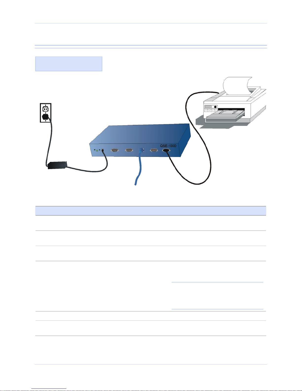
Quatech SDS User’s Manual Making connections
Making connections
Figure 6 shows a four-port
SDS connected to a printer.
Electrical
outlet
Power
cord
Power
source
You can easily connect each serial port on your SDS to any serial device
that you want to make accessible to an Ethernet network.
Figure 5 - Connecting an SDS to a serial device
Serial device
SDS
Serial cable
10/100
Ethernet
connection
Follow these steps to connect your SDS to one or more serial devices.
Step Procedure Description
Step 1 Make sure the serial device you are
The SDS should be unplugged.
connecting to the SDS is turned off.
Step 2 Connect a serial cable between the SDS
and your serial device.
Step 3 Connect an Ethernet cable between your
Ethernet outlet and the SDS’ 10/100 port.
Step 4 Insert the power source jack into the
power plug on the back of the SDS.
See Serial port(s) on page 10 for pinout
and connector information.
The Ethernet port is located on the back
panel.
An SDS requires a 5-VDC, 2-A (10-W
max) power source. The power source
ships with the SDS.
Note: These are the available power cables:
920-0111-01A Std North America
920-0112-01A Std Continental Europe
920-0113-01A Std United Kingdom
920-0114-01A Std Australia
Step 5 Plug the power source into a wall socket. The SDS powers up automatically.
Step 6 Power up the serial device. Now you are ready to install the device
drivers!
April 2008 940-0183-155 Page 13

Enabling WiFi Device Servers Quatech SDS User’s Manual
Enabling WiFi Device Servers
Note: WiFi Device Servers link
via an AP in Infrastructure
mode; they connect directly to
another device in Ad hoc mode.
Note: The Link LED on the
Ethernet port will glow green
when your wireless SDS finds
and communicates with
another device.
Quatech’s WiFi Device Servers need to have a wireless network
connection established before they can be configured for use. To
enable the wireless connection, you need to obtain the SDS’ IP
address as outlined below. Once you have the IP address, you can
configure the SDS for wireless communications via the Web interface.
In Infrastructure mode, you can use your wireless SDS just as you
would a wired SDS, but it will communicate via an access point on
the 802.11b/g network rather than through an Ethernet cable. The
SDS will scan all channels until it finds an AP, at which time the
Link LED on the Ethernet port will glow green.
The following briefly describes how to obtain the IP address of the SDS
and to enable wireless communications. For greater detail, see Installing
the device drivers on page 16 and Setting network parameters on page 47.
Page 14 940-0183-155 April 2008

Quatech SDS User’s Manual Enabling WiFi Device Servers
Step Procedure Description
Step 1 Turn on the power to your computer
system.
Step 2 Insert the Quatech SDS installation CD-
ROM into your CD-ROM drive.
Step 3 From the Main Menu, select Install SDS.
Click Next.
Step 4 Connect the Ethernet port on your SDS
either to the NIC port on your computer
or to a switch/hub.
Step 5 Connect power to the SDS. When the SDS
is ready, click the Next button to search
for Serial Device Servers.
Step 6 When the search is finished, find your
SDS and make note of its IP address.
Press Cancel to abort the installation
procedure.
Step 7 Open your Web browser and type the IP
address for the SDS in the Web browser’s
URL (address) field.
Step 8 Click on Network in the selection bar.
If the CD-ROM does not launch
automatically, select Start – Run from the
Task bar, browse to the CD-ROM drive,
and select the ThinQ.exe file. Click “OK” in
the Run window to launch the installation.
Use a CAT5 or better Ethernet cable to attach
the SDS.
When the SDS is ready, the Status, Power,
and Link LEDs should glow.
You will need this address for the network
configuration.
The Quatech Device Server Home page
displays.
Step 9 Select Infrastructure as the Access Mode.
Step 10 Configure the Device Server’s SSID to
match the access point’s SSID.
To communicate wirelessly, the AP and the
SDS must both use the same SSID. If you
don’t know the proper SSID, check with your
system administrator.
Note: The Channel setting is only used in Ad hoc
mode. In Infrastructure mode, the AP determines
the channel.
Step 11 Press Submit to configure the SDS with
your settings.
Step 12 Reset the SDS. Click on the link to perform a remote reset,
The IP Address Update successful screen
displays.
and then press Reset.
Step 13 Remove the Ethernet cable from the SDS
during the reset process.
Step 14 Leaving the Ethernet port unconnected,
perform the procedure shown in Installing
the device drivers starting on page 16,
skipping □ Step 6.
Be sure to remove the Ethernet cable before
the reset process is finished.
When you are finished, you are ready to
install your wireless SDS in its final location.
For details on connecting your wireless SDS
to a serial device, see Making connections
starting on page 13, skipping □ Step 3.
April 2008 940-0183-155 Page 15

Installing the device drivers Quatech SDS User’s Manual
Installing the device drivers
Note: You must install the
drivers on the installation CDROM on every computer that
accesses the device(s) attached
to the SDS.
This section explains how to install the SDS software under the
Windows 2000, Windows NT4, and Windows XP operating systems.
The Quatech Device Server Install Wizard helps you to add new SDS
hardware. It takes into account a variety of circumstances and directs
you to jump to different Steps as needed. Click on the blue “Go to
Hint: Click on Go to □ Step in
the rightmost column to jump
to your next step.
□ Step” text in the Description column to automatically jump to that
step. Continue from that point until you are directed to a different location.
Step Procedure Description
Step 1 Turn on the power to your computer system. This is the client PC in which the SDS
drivers are to be installed.
Step 2 Insert the Quatech SDS installation CD-
ROM into your CD-ROM drive.
Step 3 The CD-ROM should launch automatically.
If the CD-ROM does not launch
automatically, select Start – Run from the
Task bar, browse to the CD-ROM drive,
and select the ThinQ.exe file. Click “OK” in
the Run window to launch the installation.
This is the CD that shipped with the SDS.
The Quatech Serial Device screen displays,
followed by the Main Menu screen.
Continue with □ Step 4.
The Quatech Serial Device screen displays,
followed by the Main Menu screen.
Continue with □ Step 4.
Figure 6 - Main Menu screen
Figure 7 illustrates the Quatech
Install Wizard’s Main Menu
screen. The Wizard helps you
to install the drivers and
configure the SDS. This
installation adds the SDS to
the devices in the Windows
Device Manager under Multiport serial adapters and
installs the serial port(s) as it
would a standard COM port(s)
under Ports (COM & LPT).
Note: Press the Help key for
additional information as you
go through the installation
procedure.
Step Procedure Description
Step 4 From the Main Menu, select Install SDS. The Quatech Install Wizard launches and
displays the Welcome screen. Continue
with □ Step 5.
Page 16 940-0183-155 April 2008
Quatech SDS User’s Manual Installing the device drivers
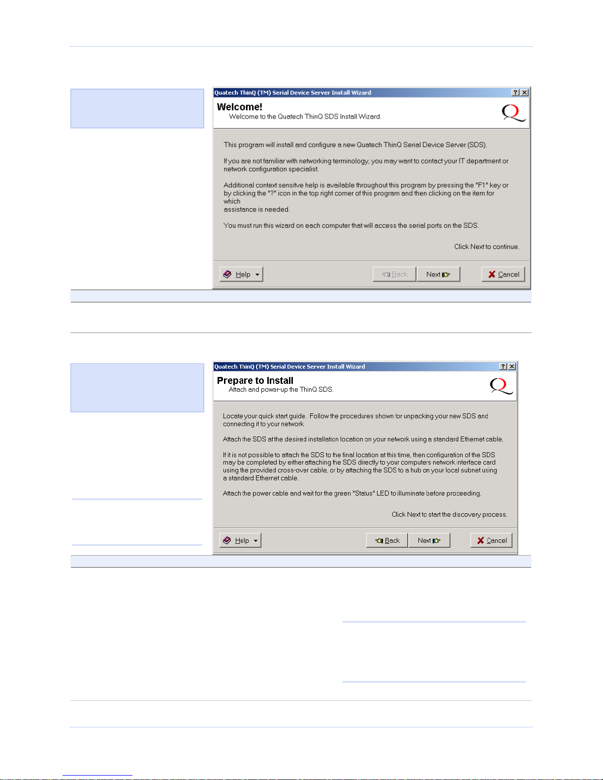
Figure 7 - Welcome screen
Figure 8 illustrates the Quatech
Install Wizard’s Welcome
screen.
Step Procedure Description
Step 5 Click the Next button to continue. The Prepare to Install screen displays.
Continue with □ Step 6.
Figure 8 - Prepare to Install screen
Figure 9 illustrates the Prepare
to Install prompt. Be sure to
read this screen carefully
before proceeding.
Note: Press the Help key for
additional information as you
go through the installation
procedure.
Step Procedure Description
Step 6 Connect the Ethernet port on your SDS to
one of the following:
¾ Desired installation location,
¾ Hub on your local subnet, or
¾ Network Interface Connection (NIC)
on your computer using an Ethernet
crossover patch cable.
If you cannot immediately attach the SDS
to the target installation site, temporarily
attach it to the local hub or your computer’s
NIC for configuration purposes.
Notes: Use a CAT5 or better Ethernet cable
to attach the SDS to your network.
If your SDS is pre-configured for your
network, attach it now to the appropriate
subnet location.
April 2008 940-0183-155 Page 17
Continue with □ Step 7.
Installing the device drivers Quatech SDS User’s Manual
Step Procedure Description
Step 7 Connect power to the SDS. Connect the cable attached to the power
source to the SDS. Plug the connector of
the unattached power cable into the
power source’s socket. Plug the other end
of the cable into a power outlet. The SDS
powers up and the blue Power LED
lights.
Step 8 Confirm that the SDS is ready to proceed. The Status LED to the left of the power
jack should glow green. The Power LED
should glow blue and the Link LED
should glow green.
Step 9 Click the Next button to search for device
servers.
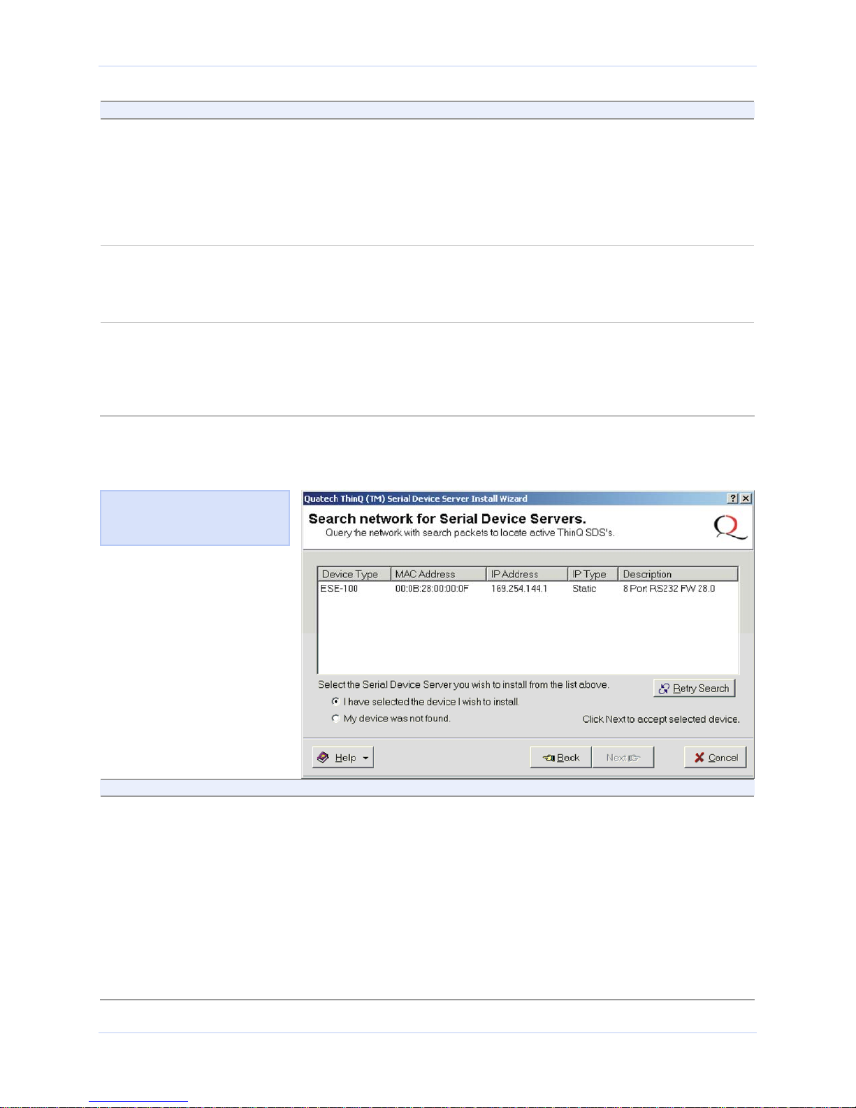
Figure 9 - Search network for Serial Device Server(s) screen
Figure 10 shows the search
results for all active device
servers on the local subnet.
The Search network for Serial Device
Servers screen displays and the Wizard
searches the local subnet for active serial
device servers.
Continue with □ Step 10.
Step Procedure Description
Step 10 When the search is completed, look in the
list of detected devices.
¾ If you find your SDS, highlight it and
click on I have selected the device I
wish to install. Press Next.
¾ If you do not see your SDS, click on
the Retry Search button. If it still is
not found, click on “My device was not
found.” Press Next.
Page 18 940-0183-155 April 2008
Continue with □ Step 11.
The Locate the Serial Device Server
screen displays. Go to □ Step 42.
Quatech SDS User’s Manual Installing the device drivers
Step Procedure Description
Step 11 One of two possible screens displays:
¾ Where is the Serial Device Server
attached?
¾ Reconfigure the Serial Device Server
If your SDS is directly connected to your
computer or to the local subnet, the
Where is the Serial Device Server
attached screen displays.
Continue with □ Step 12.
If your SDS is remotely connected, the
Wizard offers you the option to change
the configuration and move the SDS to
the subnet where it will be permanently
installed. The Reconfigure the Serial
Device Server screen displays.
Go to □ Step 30.
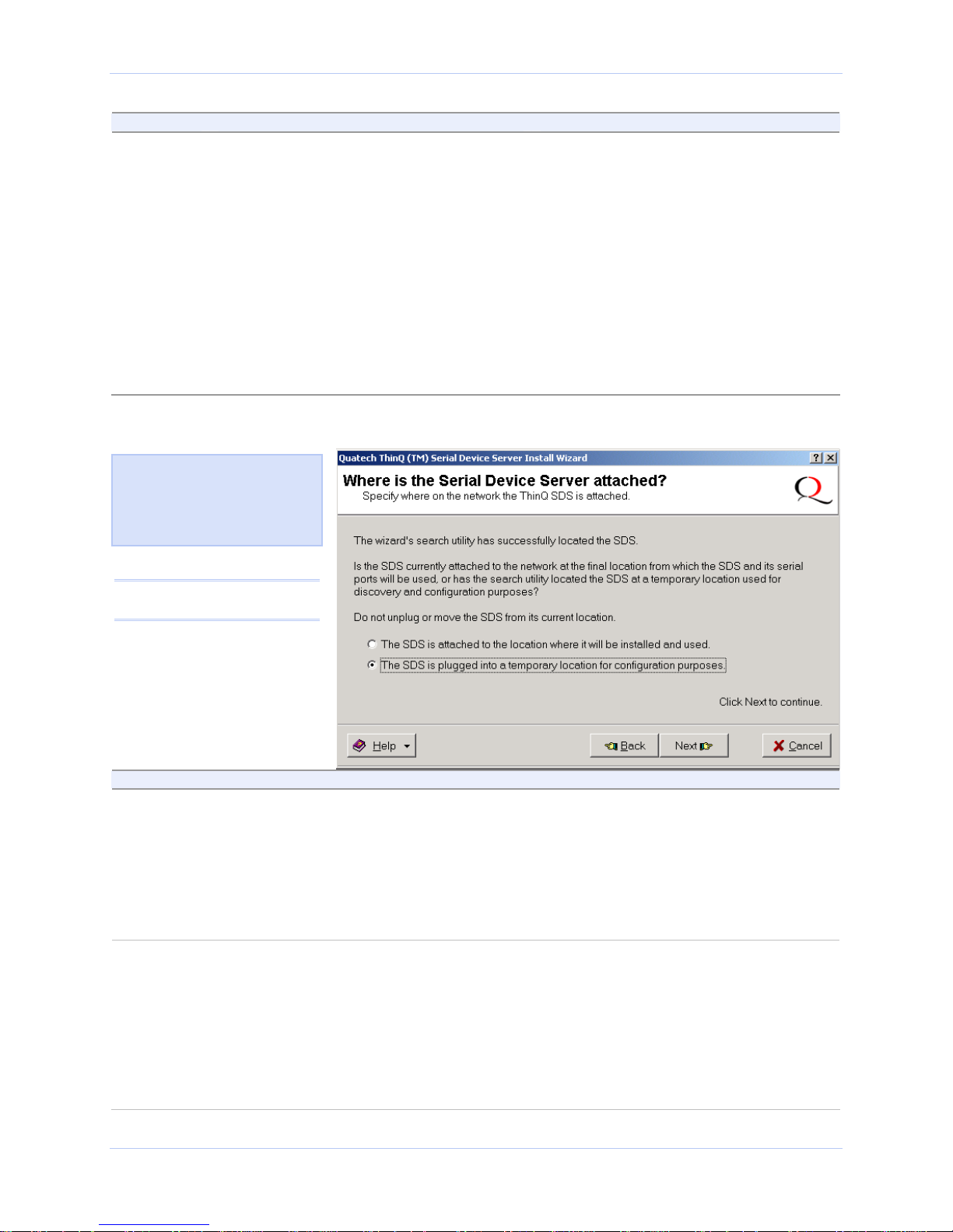
Figure 10 - Where is the Serial Device Server attached screen
Figure 11 asks you to specify
whether the SDS is in its final
installation location of if it is
temporarily installed while you
configure it.
Caution! Do not unplug or
move the SDS at this time.
Step Procedure Description
Step 12 Select one of two options:
¾ The SDS is attached to the location
where it will be installed and used.
¾ The SDS is plugged into a temporary
location for configuration purposes.
Choose this option if the SDS is
installed where you intend to use it.
Continue with □ Step 13.
Choose this option if you need to move
the SDS to another location before using
it. Continue with □ Step 13.
Step 13 Press Next to continue.
One of two possible screens displays:
¾ Network Connectivity Test
¾ Reconfigure the Serial Device Server
If your SDS is installed in its final location,
the Network Connectivity Test screen
displays. Continue with □ Step 14.
The Wizard helps you to configure and
move the SDS to its permanent spot.
Go to □ Step 30.
April 2008 940-0183-155 Page 19
Installing the device drivers Quatech SDS User’s Manual
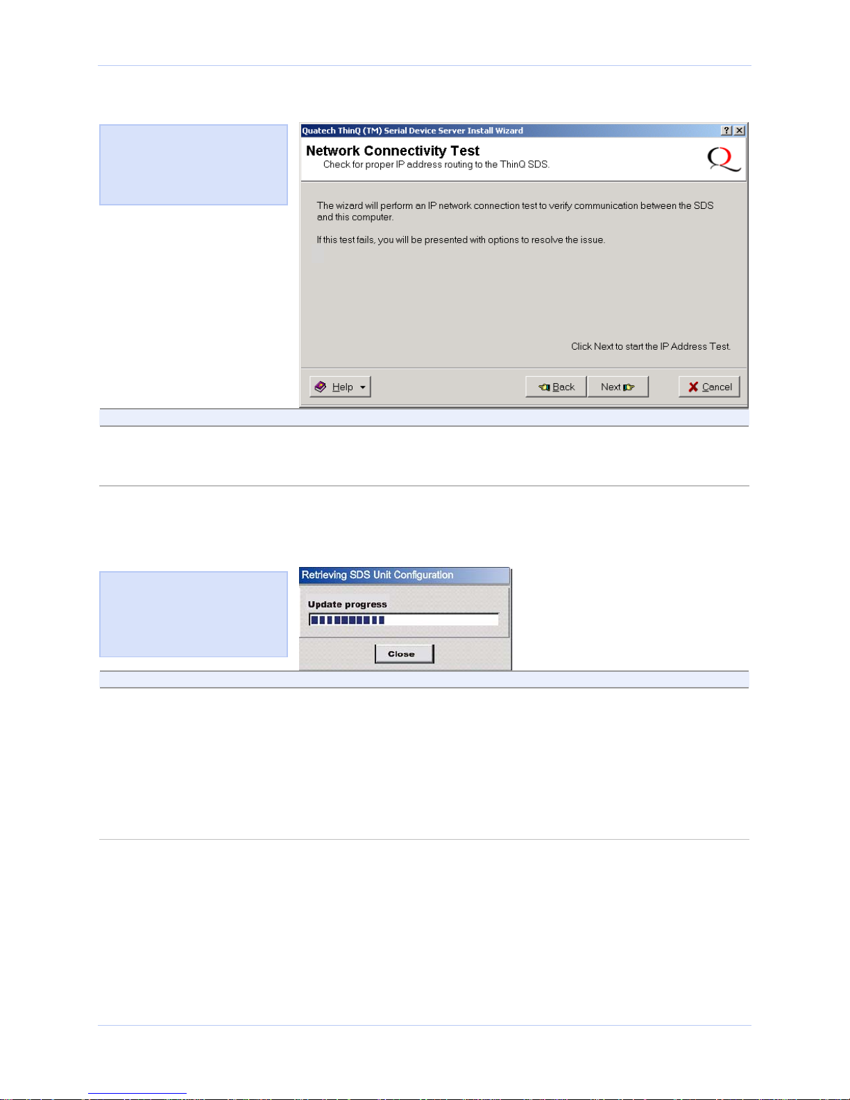
Figure 11 - Network Connectivity Test screen
Figure 12 shows the Network
Connectivity Test prompt. This
prompt informs you that the
Wizard is ready to check the IP
connectivity of the SDS.
Step Procedure Description
Step 14 Press the Next button to run the IP
connectivity test.
The Retrieving Unit Configuration popup box displays briefly.
Continue with □ Step 15.
Figure 12 - Retrieving Unit Configuration pop-up box
Figure 13 shows the Retrieving
Unit Configuration pop-up box.
This box shows the configuration
retrieval progress and closes
when it is complete.
Step Procedure Description
Step 15 Depending on whether the test passes or
fails, one of two screens displays:
¾ TCP/IP Network Configuration
Parameters
¾ Network Connectivity Test Failed
If the test passes, the TCP/IP Network
Configuration Parameters screen
displays. Continue with □ Step 16.
If the test fails, the Network Connectivity
Test Failed screen displays.
Go to □ Step 55.
Page 20 940-0183-155 April 2008
Quatech SDS User’s Manual Installing the device drivers
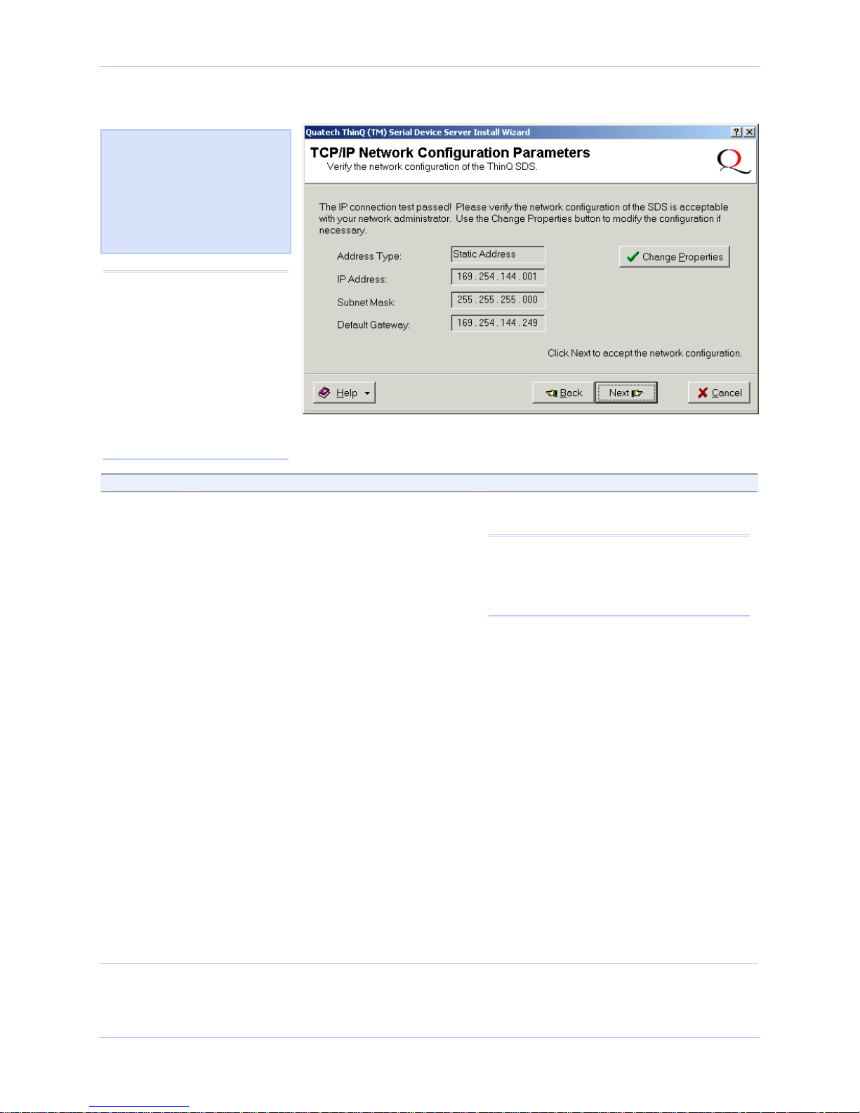
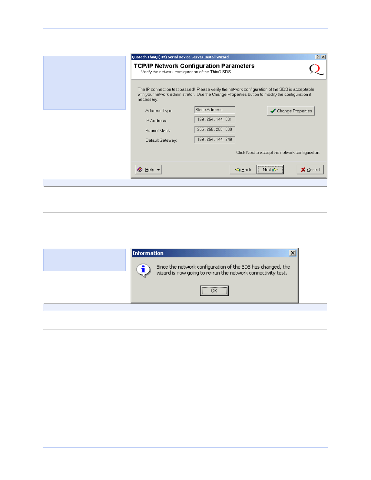
Figure 13 - TCP/IP Network Configuration Parameters screen
Figure 14 shows the following
TCP/IP network configuration
parameters:
¾ Address type
¾ IP Address
¾ Subnet mask
¾ Default gateway
Caution! If your address
type is Dynamic, the Wizard
asks you to confirm that
you want the DHCP server
to assign the IP address for
your SDS. Be aware that if
your DHCP server is not
configured to assign the
same address to the SDS
every time, communication
with the SDS may fail should
the SDS ever be reset.
Step Procedure Description
Step 16 Note the TCP/IP configuration parameters.
¾ If you need to change the parameters,
press the Change Properties button.
¾ If you are satisfied with the
parameters, press the Next button.
One of two possible screens displays,
depending on whether your address
type is:
Static Address
or
Assigned by DHCP.
The SDS initially ships with a DHCP
address type.
Note: If the SDS is attached to a network
utilizing a DHCP server, it will ask for and
obtain a valid IP address from that server.
If not, the SDS will default to the IP
address 192.168.192.168.
The Internet Protocol (TCP/IP)
Properties dialog box displays.
Continue with □ Step 17.
If your address type is Static Address,
the Install the Device Drivers screen
displays. Go to □ Step 27.
If your address type is Assigned by
DHCP, the DHCP server will assign an
IP address for your SDS. The DHCP
confirmation pop-up box displays.
Go to □ Step 40.
April 2008 940-0183-155 Page 21
Installing the device drivers Quatech SDS User’s Manual
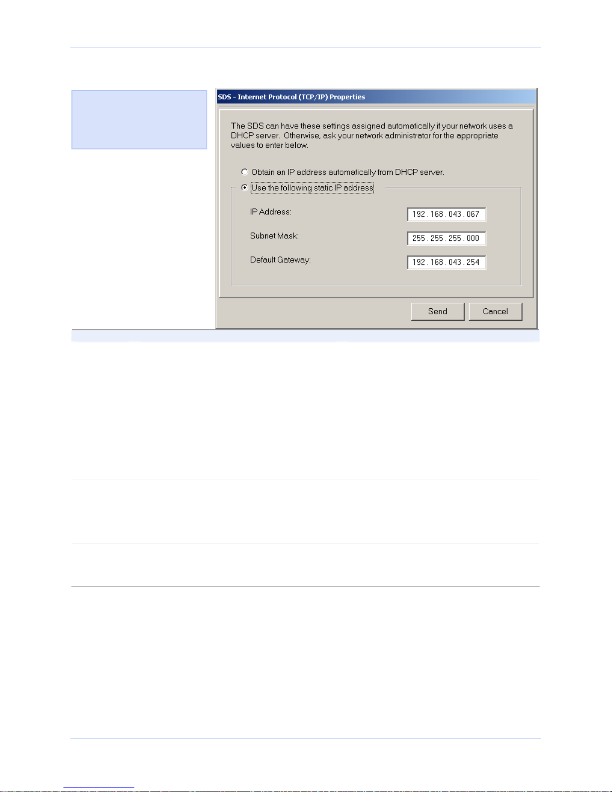
Figure 14 - Internet Protocol (TCP/IP) Properties dialog box
Figure 15 shows the current
configuration parameters for
the SDS. You can change these
parameters by keying in the
desired values.
Step Procedure Description
Step 17 The Internet Protocol Properties (TCP/IP)
dialog box lets you change the SDS
configuration so that it can operate in its
permanent location.
Select one of the following options:
¾ Use the following static IP address.
¾ Obtain an IP address automatically
If you are not sure of the configuration
parameters, consult your system
administrator.
Note: For reliable operation, we recommend
a static IP address.
Continue with □ Step 18.
Go to □ Step 19.
from the DHCP server.
Step 18 Key in any necessary changes to the:
¾ IP address,
¾ Subnet mask, and
If you are not sure of the configuration
parameters, consult your system
administrator for the specific
parameters.
¾ Default gateway.
Step 19 Press Send to send your changes to the
SDS.
The Restart confirmation pop-up box
displays.
Continue with □ Step 20.
Page 22 940-0183-155 April 2008
Quatech SDS User’s Manual Installing the device drivers
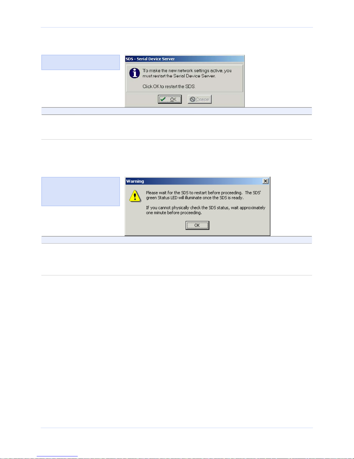
Figure 15 - Restart confirmation pop-up box
Figure 16 shows the Restart
confirmation pop-up box.
Step Procedure Description
Step 20 Press OK to restart the SDS and make
your changes active.
The SDS reboots and takes on the new
configuration. The Information pop-up
box displays. Continue with □ Step 21.
Figure 16 - Information pop-up box
Figure 17 warns you that the
SDS needs time to reset. Wait
until the Status LED glows
green, and then press OK.
Step Procedure Description
Step 21 When the Status light glows green, press
OK.
The glowing Status light indicates that
the SDS is ready. The TCP/IP Network
Configuration Parameters screen displays.
Continue with □ Step 22.
April 2008 940-0183-155 Page 23
Installing the device drivers Quatech SDS User’s Manual
Figure 17 - TCP/IP Network Configuration Parameters screen
Figure 18 shows the TCP/IP
network configuration parameters
including the following:
¾ Address type
¾ IP Address
¾ Subnet mask
¾ Default gateway
Step Procedure Description
Step 22 Press the Next button to continue. The Rerun network connectivity test pop-
up box displays.
Continue with □ Step 23.
Figure 18 - Rerun network connectivity test pop-up box
Figure 19 shows the Rerun
network connectivity test popup box.
Step Procedure Description
Step 23 Press the OK button to continue. The Network Connectivity Test screen
displays. Continue with □ Step 24.
Page 24 940-0183-155 April 2008
 Loading...